Content
.........................................................................................................................................................................................................
.......................................................................................................................................................................................
...................................................................................................................................................................................................
...............................................................................................................................................................
....................................................................................................................................................................................
................................................................................................................................................................
...........................................................................................................................................
.............................................................................................................................................................
..............................................................................................................................................................
.........................................................................................................................................................................................
.................................................................................................................................................................................................................
.........................................................................................................................................................................................................
.............................................................................................................................................................................
.............................................................................................................................................................................................................
.....................................................................................................................................................................................................................
................................................................................................................................................................................................
.........................................................................................................................................................................................
.................................................................................................................................................................
......................................................................................................................................................................................................
........................................................................................................................................................................................
...........................................................................................................................................................................................
..........................................................................................................................................................................................
.........................................................................................................................................................................................
.................................................................................................................................................................
..................................................................................................................................................................................................................
...........................................................................................................................................................
.............................................................................................................................................................................
.....................................................................................................................................................................................
.........................................................................................................................................................................................
Picture list
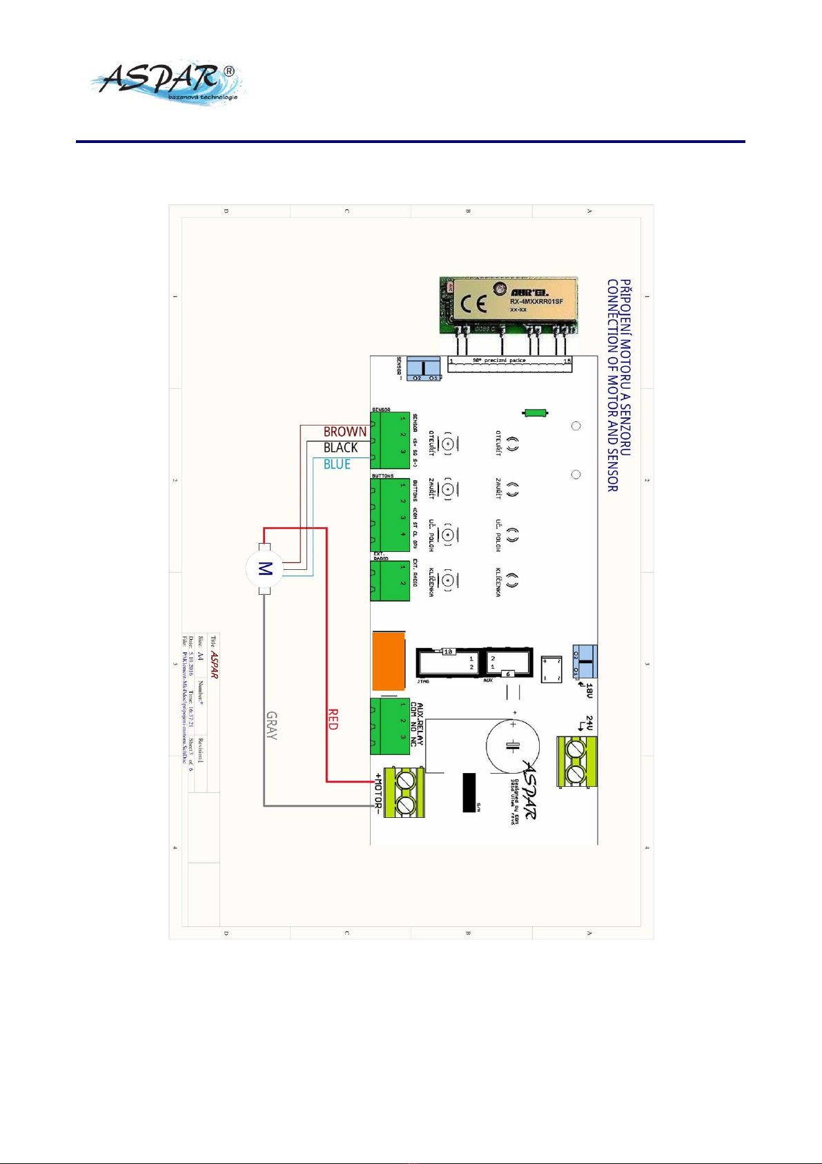
Picture 1: Motor and sensor connection ...................................................................................................................................................... 10
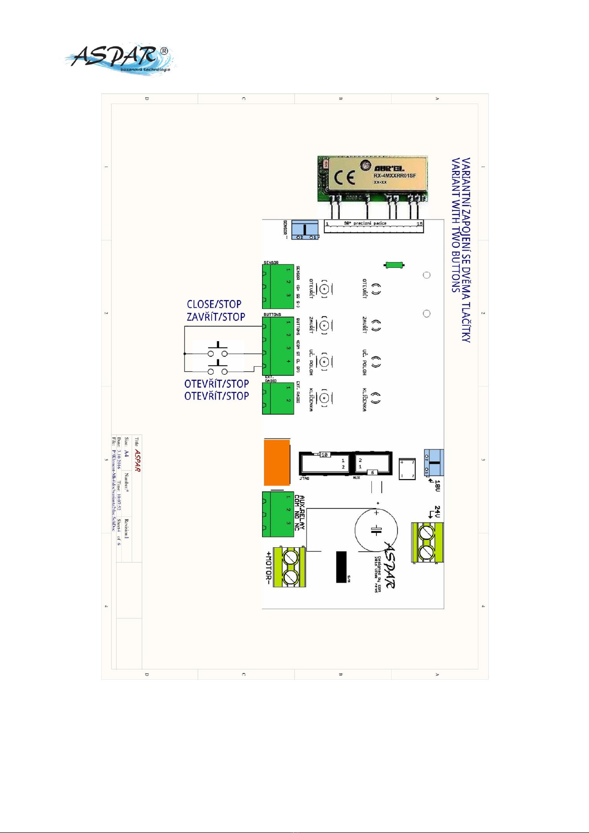
Picture 2: Version of connection of external buttons with 2 buttons................................................................................................ 11
Picture 3: Version of connection of external buttons with 3 buttons................................................................................................ 12
Picture 4: Connecting the Level Sensor ........................................................................................................................................................ 13
Picture 5: Connecting an external antenna................................................................................................................................................ 14
Picture 6: Use of auxiliary relay ...................................................................................................................................................................... 15
Picture 7: Version EVO-15.................................................................................................................................................................................. 16
1. Introduction