Aspen RMC-800 User manual

24 St. Martin Dr.
Marlborough, MA 01752
Installation and Operation Instructions
Rack Mount Chiller (RMC-800, RMC-1100)
FP00091, FP00101
Installations Notes
Date of Purchase
Date of Installation
Installer
Model Number
Serial Number

OM00020 Rev 2, FP00091, FP00101 Operation Manual Page 2of 15
Contents
System Information ......................................................................................................................................3
Safety ............................................................................................................................................................3
General Operation ........................................................................................................................................4
Environmental...........................................................................................................................................4
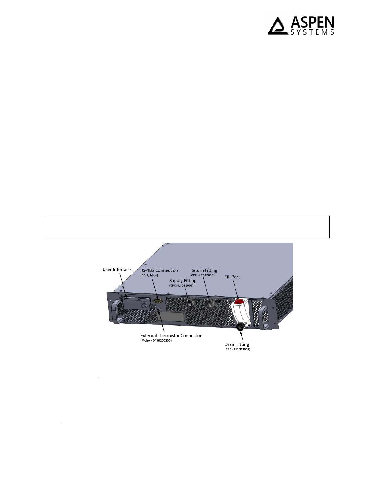
Coolant Interface ......................................................................................................................................4
Coolant Connections.............................................................................................................................4
Filling.....................................................................................................................................................4
Draining.................................................................................................................................................5
Airflow...................................................................................................................................................5
Other Considerations............................................................................................................................5
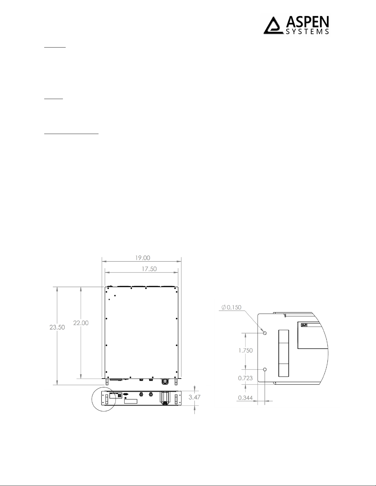
Mounting...................................................................................................................................................5
Electrical Interface ....................................................................................................................................6
External Thermistor ..................................................................................................................................6
Performance .................................................................................................................................................6
Cooling Capacity........................................................................................................................................6
Performance Curves..................................................................................................................................6
Coolant Flow Rate.....................................................................................................................................7
Controller Interface.......................................................................................................................................8
Primary Functionality................................................................................................................................8
Changing the Setpoint ..........................................................................................................................8
Starting the RMC...................................................................................................................................9
Turning off the RMC..............................................................................................................................9
Operating Modes..................................................................................................................................9
Parameter Tree .......................................................................................................................................10
Controller Login.......................................................................................................................................11
System Errors..........................................................................................................................................11
Faults...................................................................................................................................................11
Clearing Faults.....................................................................................................................................11
Warnings.............................................................................................................................................11
Communication...........................................................................................................................................11
Maintenance...............................................................................................................................................14
Customer Service ........................................................................................................................................14
Commercial Product Warranty ...............................................................................................................14
Warranty Repairs ....................................................................................................................................15
Technical Support ...................................................................................................................................15
Aspen Contact Information.....................................................................................................................15

OM00020 Rev 2, FP00091, FP00101 Operation Manual Page 3of 15
System Information
The Rack Mount Chiller (RMC-800, RMC-1100) is a turn key 2U (3.5 in. tall) chiller system. The RMC
provides a user interface to control the coolant setpoint, pump speed and alarm settings. The system
maintains coolant supply temperature with a PID loop that varies the compressor speed. Details on the
system interface and performance are included below.
Figure 1: RMC-800 (FP00091) or RMC-1100 (FP00101)
Safety
The RMC contains Tetrafluoroethane (R-134a) as a refrigerant. R-134a is an approved long-term
replacement for CFC-based refrigerants and an approved ozone depleting substance (ODS) alternative.
In the event that the RMC is damaged, general work clothing, leather gloves, and eye protection should
be worn to prevent exposure to refrigerants. The RMC also contains Polyolester (POE) oil, which is used
by the compressor. Contact Aspen for the MSDS for either of these internal fluids.
Precautions relating to the personnel hazards regarding contact with this substance should be outlined
in training and technical manuals.
Disposal of R-134a must comply with federal, state, and local disposal or discharge laws.
WARNING! R-134A is subject to U.S. Environmental Protection Agency Clean Air Act
Regulations Section 608 in 40 CFR Part 82 regarding refrigerant recycling, therefore the
refrigerant must be evacuated from the RMC prior to disposal of the assembly.
CAUTION! Skin contact with refrigerant may cause frostbite.

OM00020 Rev 2, FP00091, FP00101 Operation Manual Page 4of 15
General Operation
Environmental
Coolant Koolance 702 (contact Aspen for use of other coolants)
Ambient (Operation) 5°C to 40°C (41°F –104°F)
Ambient (Storage) -20°C to 50°C (-4°F –122°F)
Weight RMC-800 (FP00091) –10.4 kg (23.0 lb)
RMC-1100 (FP00101) –11.0 kg (24.0 lb)
Size 55.9 x 48.3 x 9.0 cm (22.0 x 19.0 x 3.5 in)
Coolant Interface
Aspen recommends using Koolance 702 as the working fluid for this system. The use of water without
additives may result in corrosion and/or biological growth in an untreated system. The coolant and
customer coolant loop should be clean and free of debris. The RMC is equipped with an internal coolant
filter; however, this filter is intended to protect the pump from debris in the coolant loop. The presence
of foreign materials into the RMC, could damage components and reduce system performance. Aspen
recommends that the customer use an external filter prior to the return line to prevent any foreign
material from returning to the RMC.
Figure 2 - RMC Front Panel
Coolant Connections
The coolant connections for the RMC are female LC Series CPC (Colder Products) quick disconnect
fittings (see Figure 2), with shutoff valves. Male mating connectors (with shutoff valves) must be
attached to both fittings at startup.
Filling
The RMC contains a 1 L reservoir. The reservoir is filled by removing the red fill cap at the front of the
system (see Figure 2). The system must be about 50% full to operate. Overfilling the systems is not
recommended to prevent possible spillage.
Aspen recommends an external coolant filter on the return line to prevent any damage to
internal components or degradation of the RMC’s cooling capacity and efficiency.

OM00020 Rev 2, FP00091, FP00101 Operation Manual Page 5of 15
Draining
To drain the system, a female LC series CPC (Colder Products) quick disconnect fitting is located at the
bottom of the reservoir (see Figure 2). Attaching a mating male quick connect and allowing to drain
under gravity will empty the reservoir. Additional coolant will remain within the system, which cannot
be drained by gravity.
Airflow
The RMC requires airflow to sufficiently cool the system. Aspen requires at least 4 inches of clearance in
front of the air inlet (front panel) and the air exhaust (rear).
Other Considerations
The RMC has two exposed un-insulated sections (the quick connect fittings and the reservoir). If
operating in an environment where the coolant temperature is below the dew point of the ambient air,
these surfaces will collect condensation. To prevent condensation from forming, these surfaces must be
insulated by the user.
While the Koolance 702 fluid depresses the freezing temperature of the coolant (-15°C, 5°F), it may be
possible to freeze during operation. The RMC can freeze a fluid at a setpoint greater than the freezing
point of the coolant. Care must be taken to not operate at a coolant temperature within 5°C of the
freezing point of that coolant.
Mounting
The RMC is a rack mount chiller (2U). The outer dimensions and mounting dimensions are defined in
Figure 3. Some customers may wish to have the RMC as a desktop unit, and for that, Aspen can
recommend adhesive feet for the unit.
Figure 3: RMC Dimensional Drawing - Note all dimensions are in inches

OM00020 Rev 2, FP00091, FP00101 Operation Manual Page 6of 15
Electrical Interface
Input Voltage 120 VAC or 240 VAC (24 VDC available upon request from Aspen but
is dimensionally different). Input voltage is specified at time of
purchase with Aspen.
Maximum Power 600 W (5 A at 120 VAC, 2.5 A at 24 VDC)
Figure 4: RMC Power Interface
External Thermistor
The RMC has an electrical connector to support an external thermistor, if desired (not supplied). This
external thermistor if the customer wishes to use the RMC to control to an external temperature (i.e.
mounted on the heat source) or if the customer wishes to control the coolant to above ambient.
The connector for the external thermistor is a 2 pin connector, Molex Microfit (part number:
0430200200). The user must connect to this with wire harness that consists of a mating connector and a
NTC 10 kOhm thermistor (Type 2). The type of thermistor is dependent on the customer’s application,
but Aspen can provide guidance if needed.
Performance
Cooling Capacity
Each RMC is qualified to meet a performance threshold at 20°C ambient, 20°C coolant, with a flow rate
of 3.5 L/min using Koolance 702 fluid. The performance threshold for each version of the RMC is as
follows:
RMC-800 (FP00091) 800 W
RMC-1100 (FP00101) 950 W
Performance Curves
The performance curve below (Figure 5) defines the nominal performance of the RMC. The data shown
below is derived using coolant flow and Koolance 702 coolant as a function of coolant temperature and
ambient temperature.
CAUTION! The RMC must be operated in the vertical orientation. Operation of the
system at an orientation off from vertical will result in reduced system capacity or
damage to the compressor.
CAUTION! Operating the RMC outside the voltage range will void the system warranty.

OM00020 Rev 2, FP00091, FP00101 Operation Manual Page 7of 15
Figure 5: RMC-1100 Performance Map
Figure 6: RMC-800 Performance Map
Coolant Flow Rate
The RMC is equipped with a positive displacement pump. Using Koolance 702 as a coolant, the system
can generate the following maximum flow curve. The speed of the pump may be reduced should the
user desire less flow.

OM00020 Rev 2, FP00091, FP00101 Operation Manual Page 8of 15
Figure 7: RMC Pressure/ Flow Curve
The RMC is equipped with a bypass valve to prevent the pump from generating excessive pressures. The
bypass valve begins to crack around 4.0 bar (58 psig). The bypass valve will prevent the system (and
external components) from seeing pressures greater than 6.9 bar (100 psig). This valve will open at a
lower differential pressure, as there is pressure drop in the system return line.
Controller Interface
The RMC is equipped with a controller, which monitors and controls the system. The primary interface
of the system is shown in Figure 8 below.
Figure 8: Controller Interface
During normal operation the controller displays the symbols showing the compressor, fan and pump are
operating. The display also shows the coolant temperature and the compressor speed signal (0 –100%).
These are displayed in Figure 8.
During normal operation if the user presses the button, the controller will display the setpoint
temperature.
Primary Functionality
Below are some of the critical functions of the RMC. Additional functionality can be accessed in the
parameter tree.
Changing the Setpoint
To change the setpoint, the user must do the following:
Press .

OM00020 Rev 2, FP00091, FP00101 Operation Manual Page 9of 15
Press 3 times to reach the PAR screen. Press .
Press 1 time to reach the CFG screen. Press .
Press on the Set screen.
Use the and arrows to adjust the setpoint. Press .
Press 3 times to return to the main screen.
Starting the RMC
To start the system, the user must do the following:
Press .
Press 2 times to reach the Str screen. Press .
When On is displayed, Press .
Turning off the RMC
To turn the RMC off, the user must do the following:
Press .
Press 2 times to reach the Str screen. Press .
Press 1 time to reach OFF. Press .
Operating Modes
The RMC offers 3 operating modes:
1) The RMC controls to supply temperature (at the supply CPC) (default)
2) The RMC controls to an external input thermistor (see External Thermistor, p. 6)
3) The RMC controls to an internal temperature which is 1°C greater than an external ambient
temperature. Customers may use this functionality to ensure coolant lines are non-condensing.
To select the operating mode, the user must do the following:
Press .
Press 3 times to reach the PAR screen. Press .
Press on the GEN screen.
Press on the StU screen.
Press 4 times to reach the control sensor screen (y08). Press .
Use the and arrows to select the sensor to use (internal [TI] or external [TE]). Press .
If above ambient operation is required, press once, then press to reach control mode
(y09).
Use the and arrows to select the control mode to use (direct [def] or ambient +[Amb]).
Press . Note: ambient+ mode can only be used when controlling to internal thermistor (TI).

OM00020 Rev 2, FP00091, FP00101 Operation Manual Page 10 of 15
Press 4 times to return to the main screen.
Parameter Tree
The table below represents all the functionality of the controller. Some items are only accessible by
entering the login password (see Controller Login p. 11):
Table 1: RMC Controller Tree
Level 1
Level 2
Level 3
Level 4
ALA
Alarms
AAL
Active alarms
LOG
Log history
CLR
Clear log history
LOG
Login
Str
Start
On
Turn On
Off
Turn Off
RST
Reset Alarms
PAR
Parameters
GEN
General
StU
Setup
y01
ON/OFF
y05
Temperature units
y07
Restore default parameters
y08
Control sensor
y09
Control mode
ALA
Configuration
BUZ
Buzzer activation time
AdL
Alarm relay activation delay
AOF
Alarm relay active if unit in OFF
Ser
Serial Settings
Ser
Serial address (Modbus)
bAU
Serial baudrate (Modbus)
COM
Serial settings (Modbus)
PAS
Password
L01
Password level 1
L02
Password level 2
L03
Password level 3
CFG
Unit configuration
Set
Setpoint
c01
Pump flow delay
c02
Fan delay off
c03
T1-Pv filter
c04
Alarm difference
c05
Pump shutdown delay
c06
Min compressor speed
c07
Pump speed
c08
Compressor delay off
c09
Max pump speed
c10
Min pump speed
PID
PID Settings
P01
Regulation type
P02
Gain
P03
Integral time

OM00020 Rev 2, FP00091, FP00101 Operation Manual Page 11 of 15
Controller Login
The user can access the hidden functionality of the system by entering the login password (default is
947).
System Errors
The RMC has a handful of faults and warnings which are displayed on the controller and will shut down
the system when triggered.
Faults
If a fault is triggered, it will shut down the system. The fault will display on the controller. The following
faults are displayed:
Table 2: RMC Faults
Code
Fault
Description
A01
PV Fault
Temperature Sensor Fault
E04
Compressor Fault
Compressor Fault
E02
Flow Fault
Low Flow Fault (< 0.6 L/min)
E01
Low Level Fault
Low Level Fault
Faults will NOT be cleared until the user manual clears the fault (see Clearing Faults, p. 11)
Clearing Faults
When a fault occurs, the user must clear the fault to resume operation of the system. To clear a fault,
the user must do the following:
Press .
Press 2 times to reach the Str screen. Press .
Press 2 times to reach RST. Press .
The system will resume operation as soon as RST is selected.
Warnings
If a warning is triggered, no functionality of the system is disabled. The warning will be displayed n the
controller. The following warning are displayed:
Table 3: RMC Warnings
Code
Warning
Description
E03
PV Out of range
Coolant temperature is more than 5°C out of
range -- this value can be adjusted (c04)
E05
Low Level Warning
Low Level Warning
Warnings will automatically be cleared as soon as the condition initiating the warning is resolved.
Communication
The RMC is equipped with RS-485 communication. The user can connect to the Male DB9 connector at
the front of the panel and read / write information to the controller.
To use the RS485, the following pinout is used and configured as below:

OM00020 Rev 2, FP00091, FP00101 Operation Manual Page 12 of 15
Table 4: RMC RS-485 Communication Pinout
Pin 2 –RX/D-
Pin 3 –TX/D+
Pin 5 - GND
The default communications settings are as follows, but they can be adjusted if required.
Serial address: 1
Serial baudrate: 19200
The relevant parameters for the RMC and their Application Data Unit (ADU) are defined in the Table 1
below:
Table 5: Modbus parameters
LABEL
DESCRIPTION
MIN
MAX
VALUE/TYPE
UNIT
RW
ADU
PARAMETERS & STATUS VARIABLES
StU
General > Setup
y01
ON/OFF
0
1
0 - OFF
Enum 1
RW
3001
y05
Temperature Units
0
1
0 - C
Enum 6
RW
3002
y07
Restore default parameters
0
1
0 - NO
Enum 2
RW
3003
y08
Control Sensor
0
1
0 - TI
Enum 7
RW
3030
y09
Control Mode
0
1
0 - Def
Enum 8
RW
3031
ALA
General > Configuration
BUZ
Buzzer activation time
0
15
1
min
RW
3004
AdL
Alarm relay activation delay
0
999
0
s
RW
3005
AOF
Alarm relay active if unit in OFF
0
1
1 - YES
Enum 2
RW
3006
SEr
General > Serial settings
SEr
Serial address (Modbus and CAN)
1
100
1
RW
3007
bAU
Serial baudrate (Modbus)
0
8
6 - 192
Enum 3
RW
3008
COM
Serial settings (Modbus)
0
2
0 - 8N1
Enum 4
RW
3009
CFG
Parameters > Unit config
SEt
Setpoint
-20
90
21.0
°C
RW
3013
c01
Pump Flow Delay
0
100
10
s
RW
3014
c02
Fan Delay Off
0
100
3
s
RW
3015
c03
T1-Pv Filter
0
100
1
RW
3016
c04
Alarm Diff
0
100
5.0
K
RW
3017
c05
Pump Shutdown Delay
0
100
3
s
RW
3018
c06
Min Compr Speed
0
100
20
%
RW
3019
c07
Pump Speed
0
0
80.0
%
RW
3020
c08
Compr Delay Off
0
3600
60
s
RW
3021
c09
Max Pump Speed
0
100
100.0
RW
3028
c10
Min Pump Speed
0
0
0.0
RW
3029
PID
Parameters > PID Settings
P01
Regulation Type
0
2
2 - PID
Enum 5
RW
3022
P02
Gain
0
1000
2.0
RW
3023

OM00020 Rev 2, FP00091, FP00101 Operation Manual Page 13 of 15
P03
Integral Time
0
10000
480
s
RW
3024
LOG
Status var > MCX Design Hotspots
V01
SystemOnOff
-32768
32767
0
Read
8101
C01
Reset Alarms
0
2
RW
1859
V03
PUMP STATUS
-32768
32767
0
Read
8102
V04
UnitFault
-32768
32767
0
Read
8103
V05
COMPRESSOR STATUS
-32768
32767
0
Read
8104
V06
COMPRESSOR RUN
-2^31
2^31
0
Read
8105
V07
PUMP STATUS
-32768
32767
0
Read
8107
V08
FAN RUN
-32768
32767
0
Read
8108
V09
COMPRESSOR PERCENT
-32768
32767
0
Read
8109
V10
PUMP FLOW ALARM
-32768
32767
0
Read
8111
V11
L2 WARNING
-32768
32767
0
Read
8112
V12
L1 FAULT
-32768
32767
0
Read
8113
V13
T1 OOR
-32768
32767
0
Read
8114
V14
T1 FAULT
-32768
32767
0
Read
8115
V15
T1 VALUE
-32768
32767
0
Read
8116
V16
COMPR OUT
-32768
32767
0
Read
8117
V17
PID EN
-32768
32767
0
Read
8118
V18
POWER UP
-32768
32767
0
Read
8119
V19
Cur Setpoint
-32768
32767
0
Read
8120
HLD
Main Menu > Hold
P04
Derivative Time
0
10000
90
s
RW
3025
P05
Overshooting
0
500
150
RW
3026
P06
Filter Factor Derivative Action
0
100
12
RW
3027
ALARMS
LABEL
DESCRIPTION
MIN
MAX
RESET
IN OFF
A01
Control Sensor Fault
0
1
MANUAL
INACTIVE
Read
1901 .08
E04
Compressor Fault
0
1
MANUAL
INACTIVE
Read
1901 .09
E02
Pump Flow Fault
0
1
MANUAL
INACTIVE
Read
1901 .10
E01
L1 Fault
0
1
MANUAL
ACTIVE
Read
1901 .11
E05
L2 Warning
0
1
AUTO
INACTIVE
Read
1901 .12
E03
Control Sensor Out of Range
0
1
AUTO
INACTIVE
Read
1901 .13
A02
Ambient Sensor Fault
0
1
MANUAL
INACTIVE
Read
1901 .14
I/O CONFIGURATION
AI
ANALOG INPUTS
1
Ti-Control
-50.0
110.0
NTC-TABLE
°C
Read
18502
2
Compressor Status
0.0
5.0
0-5 V
V
Read
18503
3
Ambient Temp
-50.0
110.0
NTC-TABLE
°C
Read
18507
4
Te-Control
-50.0
110.0
NTC-TABLE
°C
Read
18506
DI
DIGITAL INPUTS
1
Flow Switch
0
1
N.O.
Read
17504
2
Liquid Level L1
0
1
N.O.
Read
17505
3
Liquid Level L2
0
1
N.O.
Read
17506

OM00020 Rev 2, FP00091, FP00101 Operation Manual Page 14 of 15
AO
ANALOG OUTPUTS
1
Compressor Speed - C2
0
100
0-10 V
Read
19002
2
Pump Speed
0
100
PWM
Read
19003
DO
DIGITAL OUTPUTS
1
Compr Run
0
1
N.O.
Read
18004
2
Fan Run
0
1
N.O.
Read
18005
3
Pump Run
0
1
N.O.
Read
18006
5
Warning
0
1
N.O.
Read
18003
6
Alarm
0
1
N.O.
Read
18002
Maintenance
The RMC is a sealed unit and does not require regular maintenance to operate. Depending on
environmental conditions the air inlet could become fouled with dust and debris. This condition will
cause the RMC to operate inefficiently and potentially over-heat and shut down. The inlets to the RMC
(on the front and side faces) should be cleaned periodically with a damp cloth when the system is non-
operational.
The RMC contains an internal coolant filter which should not need to be changed if coolant remains
pure. However, if flow becomes reduced over time, it may be because the internal filter has become
fouled. Please contact Aspen should you suspect this filter has been fouled, and Aspen’s applications
engineers can help diagnose if the filter may need replacement.
Customer Service
Commercial Product Warranty
Aspen System LLC (hereinafter referred to as “Aspen”), warrants to the original purchaser that products
sold shall be free from defects in material and workmanship for the warranty period not to exceed one
year from the date of shipment. If buyer claims that a product violates such warranty, Aspen, upon
notice promptly given, will either examine the product at buyer’s site, or issue shipping instructions for
return to Aspen at buyer’s expense, transportation charges prepaid.
Aspen’s sole obligation under its warranty shall be, at its option, to repair, replace or refund the price of
any product thereof which is proved to violate such warranty. In no event, whether based on contract,
indemnity, warranty, tort (including negligence), strict liability or otherwise, shall Aspen be liable to the
buyer for special, indirect, incidental or consequential damages whatsoever including, without
limitation, loss of profit or revenue.
The above warranty is buyer’s exclusive remedy and Aspen hereby expressly disclaims all other
warranties, express or implied, including the implied warranty of merchantability and the implied
warranty of fitness for a particular purpose. The foregoing shall constitute the sole remedy of the buyer
and the sole liability of Aspen.
This Limited Warranty shall not apply to any product or component thereof which has been repaired or
altered outside of Aspen’s factory in any manner so as, in Aspen’s sole judgment, to affect its
serviceability, or to any product that has been subject to alteration, accident, misuse, abuse, neglect or
normal wear. The Limited Warranty shall not apply to products which have been assembled or installed
or used in a manner contrary to Aspen’s printed instructions, or due to failure to follow Aspen printed
instructions for operation and maintenance. This product is designed and intended to be installed and
operated in an enclosure that is sealed from the ambient environment. Exposure to water leakage into

OM00020 Rev 2, FP00091, FP00101 Operation Manual Page 15 of 15
the enclosure and/or excessive condensation from exposure to humid ambient air during operation will
void this warranty. Any technical assistance provided by Aspen’s personnel or representatives in system
design is construed to be a proposal and not a recommendation. The responsibility for determining
feasibility rests with the user and should be subject to test. Only the terms expressed in this Limited
Warranty shall apply and no distributor, corporation or individual is authorized to amend, modify or
extend this warranty in any way on resale.
Warranty Repairs
Any product returned and found to be under warranty will be repaired or replaced at the discretion of
Aspen Systems, LLC. Depending on the circumstances of the problem, it may be deemed necessary to
return the products to Aspen Systems. for repair. In order to return the product for repair, please
contact Aspen Systems via email, telephone, or through the Aspen Systems’ website (see Contact
Information)
Technical Support
Technical Support is available from Aspen Systems from 8:00 AM to 5:00 PM (EST) Monday through
Friday via phone or email (see contact information). Technical support can also be requested on-line. To
expedite assistance for problems, be able to provide the following information:
•Your name, phone number, company, division and city.
•Product number, serial number and revision (located on the RMC rear, near power switch).
•A detailed description of your problem.
Aspen Contact Information
Email: info@aspensystems.com
Phone: 508-281-5322
Website: http://aspensystems.com/contact
This manual suits for next models
3
Table of contents
Other Aspen Chiller manuals
Popular Chiller manuals by other brands

Holland Green Science
Holland Green Science 10303001 user manual

Baumatic
Baumatic BBC460SS instruction manual

Johnson Controls
Johnson Controls SABROE ComPAC installation guide

Daikin
Daikin EWAA011 016DAV3P Operation manual

Husky
Husky C4PRO-H-C-HU user manual

CLIVET
CLIVET WSAT-XIN Series Installation and operating manual