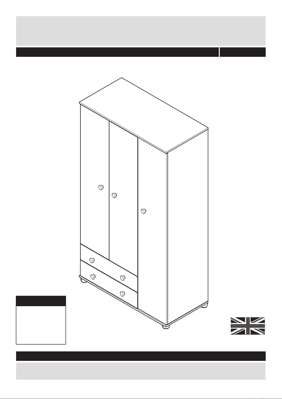
Important - Please read these instructions fully before starting assembly
Safety and Care Advice
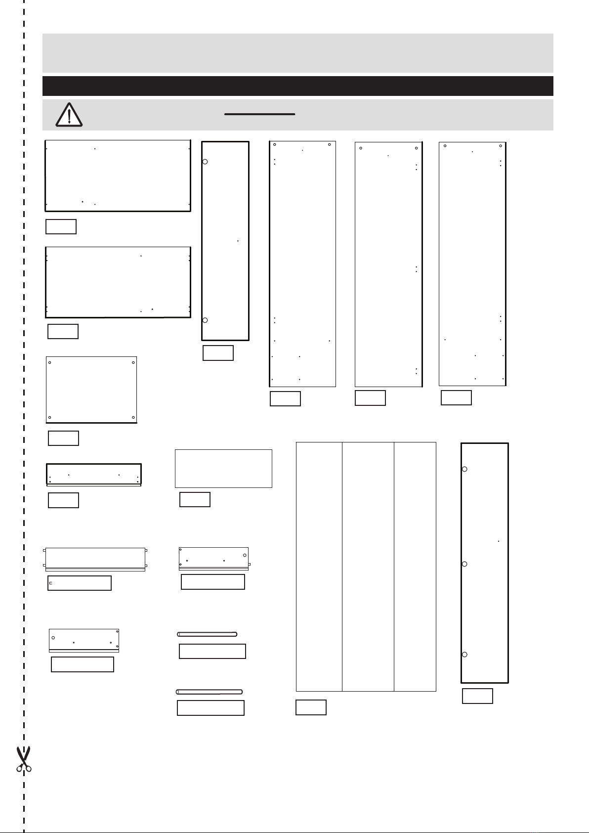
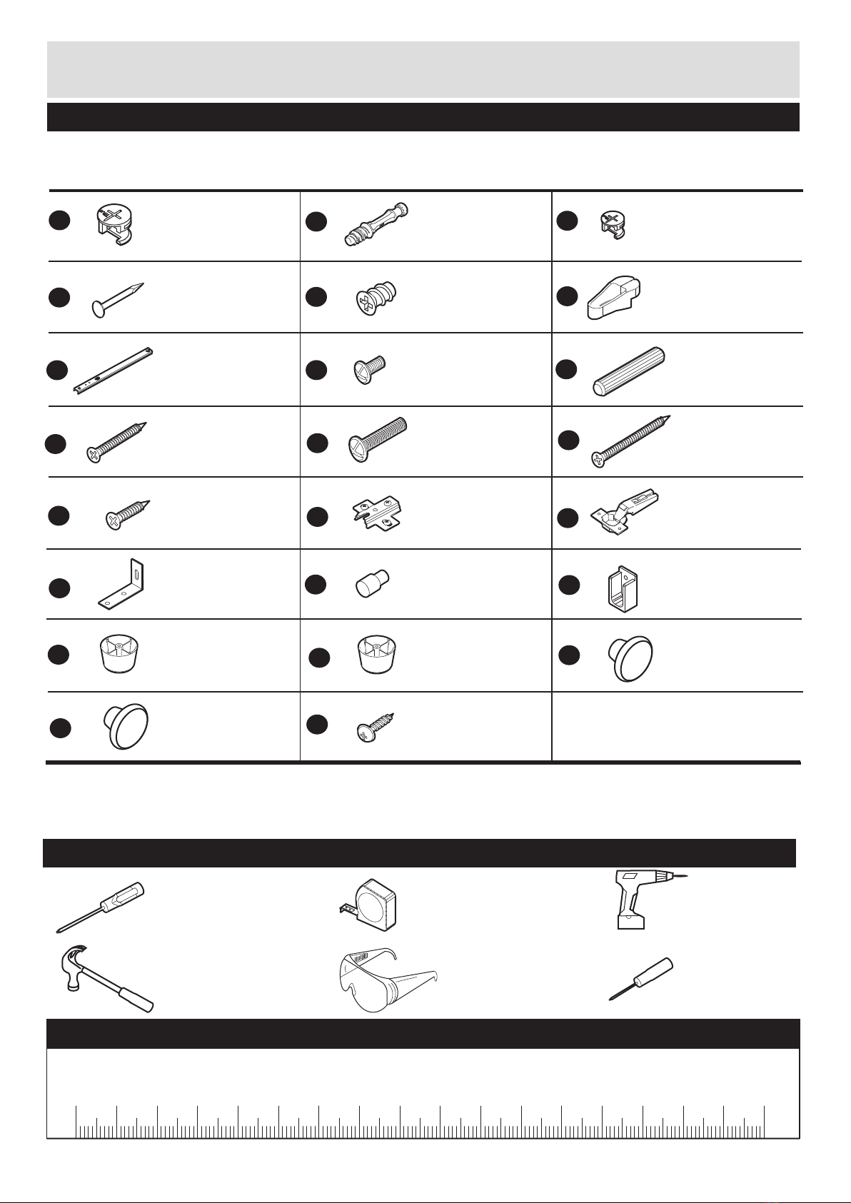
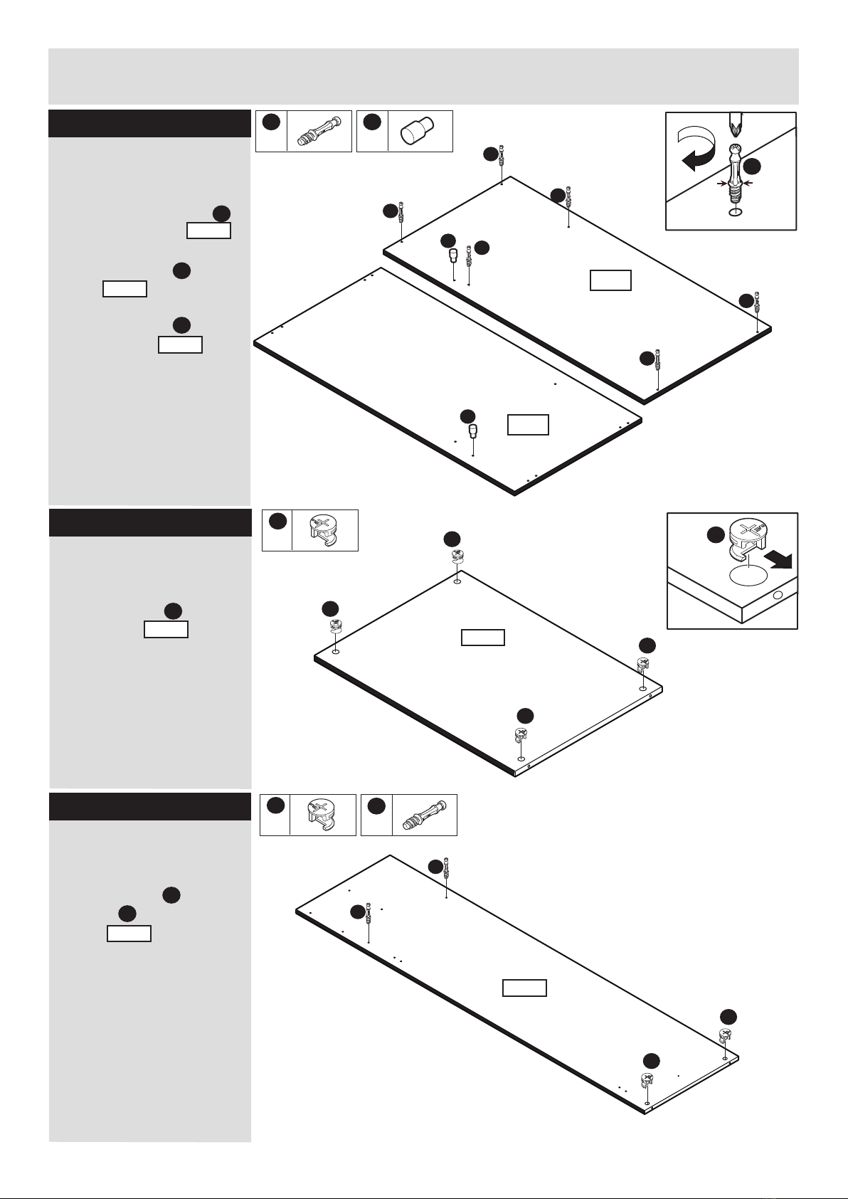
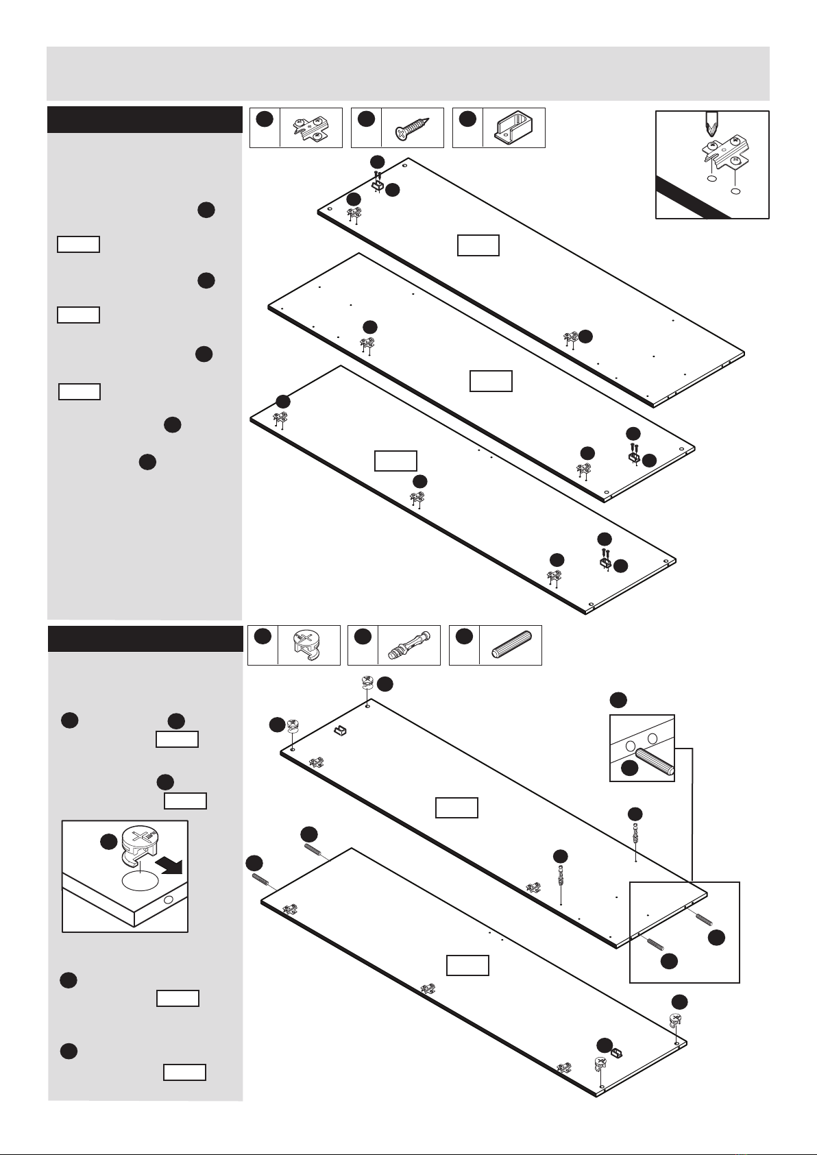
Check you have all the
components and tools listed on
pages 2 and 3.
Remove all fittings from the
plastic bags and seperate them
into their groups.
Keep children and animals
away from the work area, small
parts could choke if swallowed.
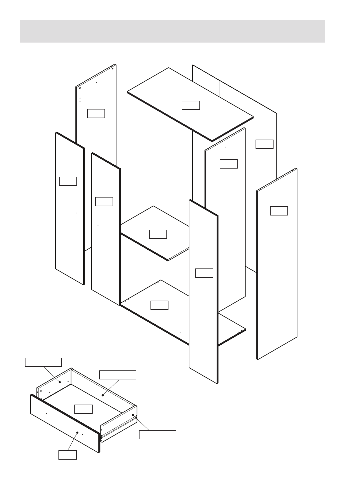
Make sure you have enough
space to layout the parts before
starting.
Do not stand or put weight on
the product, this could cause
damage.
Assemble the item as close
to its final position (in the same
room) as possible.
Assemble on a soft level
surface to avoid damaging the
unit or your floor.
Parts of the assembly will be
easier with 2 people.
We do not
recommend the
use of power
drill/drivers for
inserting screws,
as this could damage the unit.
Only use hand screwdrivers.
Care and maintenance
Always lift furniture when
moving it (do not drag)
otherwise the joints may be
damaged.
From time to time check that
there are no loose screws on
this unit.
This product should not be
discarded with household
waste. Take to your local
authority waste disposal centre.
1
Dust surfaces with a soft, dry,
lint free cloth.
More stubborn marks can be
removed using a damp
(not wet) cloth. Wipe the
surface dry immediately
using a soft lint free cloth.
Do not use detergents, abrasive
cleaning products or cleaning
products that contain ammonia,
solvents or silicone as these
may damage the surface finish.
To protect the furniture,
position the furniture out of
direct sunlight and away from
direct heat sources such as
radiators and fires.
Do not place the furniture in
excessively dry and humid
conditions.
Do not place hot or cold
objects on the surface, always
use protective mats to avoid
marking the furniture.
Clean spills up immediately
Dispose of all packaging
carefully and responsibly
when assembly complete.
Do Not dispose of packaging
until assembly complete.