manuals.online logo
Brands
  1. Home
  2. •
  3. Brands
  4. •
  5. ASROCK
  6. •
  7. Motherboard
  8. •
  9. ASROCK E3C232D4U User manual

ASROCK E3C232D4U User manual

E3C236D4U / E3C232D4U / E3C232D4U-V1L
Quick Installation Guide
www.asrockrack.com
No. Description No. Description
1VGA Port (VGA1) 5 LAN RJ-45 Port (LAN1)
2 Serial Port (COM1) 6 USB 3.0 Ports (USB3_3_4)
3LAN RJ-45 Port (IPMI_LAN)
*For E3C232D4U and E3C236D4U only 7LAN RJ-45 Port (LAN2)
*For E3C232D4U and E3C236D4U only
4 USB 3.0 Ports (USB3_1_2) 8 UID Switch (UID1)
4
2
P/N: 15G065064100AK V1.0
Install the Server Board
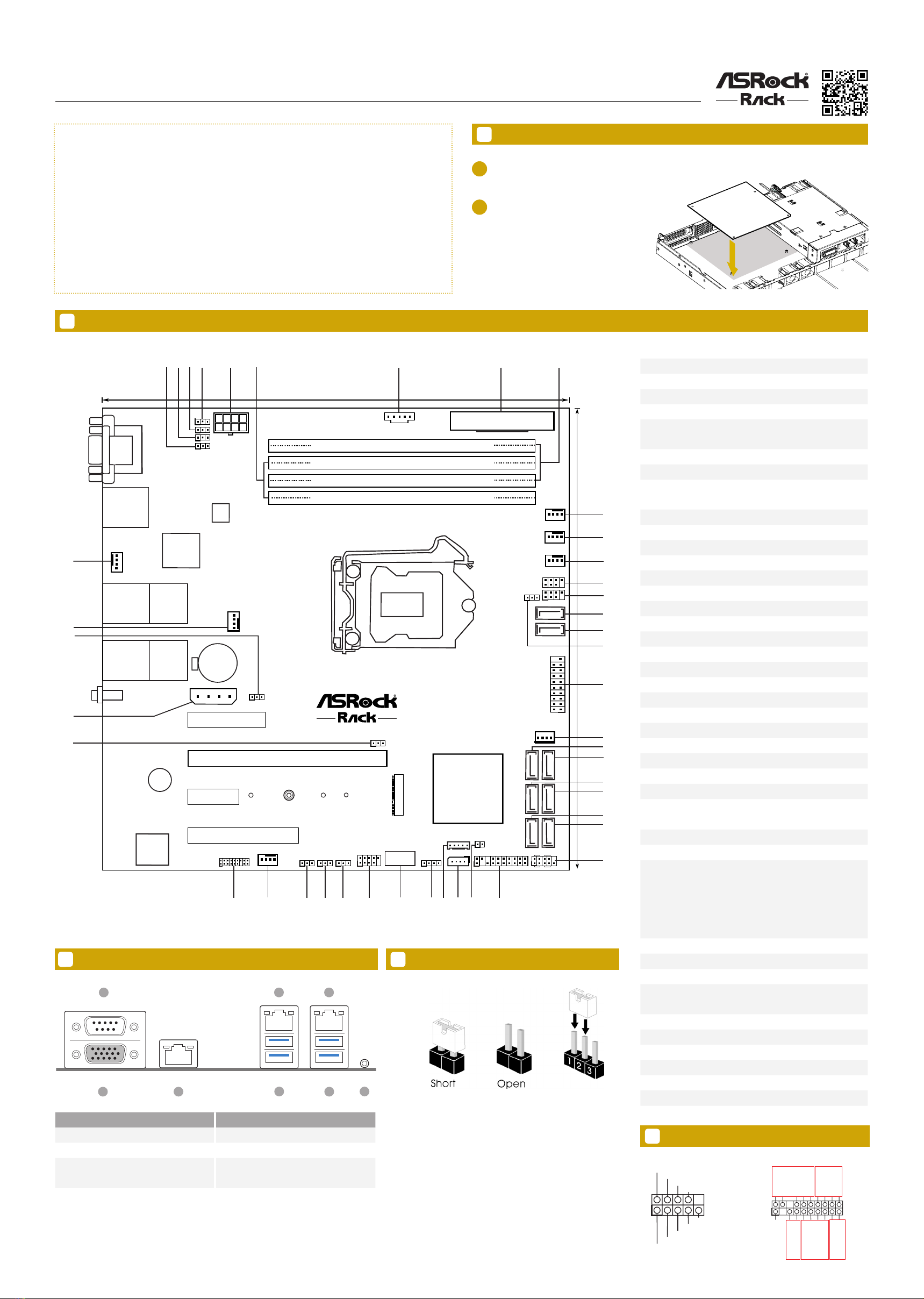
Motherboard Layout
Jumper Cap On/O
The server board User's Manual is available for download from the ASRock Rack's ofcial website
at http://www.asrockrack.com.
Take note of the following precautions before you install server board components or change any
server board settings.
1. Unplug the power cord from the wall socket before touching any components.
2. To avoid damaging the server board’s components due to static electricity, NEVER place your
server board directly on the carpet or the like. Also remember to use a grounded wrist strap or
touch a safety grounded object before you handle the components.
3. Hold components by the edges and do not touch the ICs.
4. Whenever you uninstall any component, place it on a grounded anti-static pad or in the bag
that comes with the component.
5. When placing screws into the screw holes to secure the server board to the chassis, please do
not over-tighten the screws! Doing so may damage the server board.
1
1Insert the server board into the chassis.
2Affix t he screws clockwise into t he
mounting holes in all of the corners of
the server board.
Do not over-tighten the screws
When the jumper cap is placed on the pins, the
jumper is “Short”. If no jumper cap is placed on the
pins, the jumper is “Open”.
The illustration shows a 3-pin jumper whose pin1
and pin2 are “Short” when a jumper cap is placed on
these 2 pins.
I/O Panel
DDR3_B1 (64 bit, 240-pin module)
DDR3_A1 (64 bit, 240-pin module)
PCIE7
17.0cm (9.6 in)
ATXPWR1
CPU_FAN1
COM1
VGA1
BMC
ROM
FRNT_FAN1
LAN1
USB 3.0
T: USB_1
B: USB_2
LAN2
USB 3.0
T: USB_3
B: USB_4
IPMI
LAN
DDR4_B2 (64 bit, 288-pin module)
DDR4_B1 (64 bit, 288-pin module)
DDR3_B1 (64 bit, 240-pin module)
DDR3_A1 (64 bit, 240-pin module)
DDR4_A2 (64 bit, 288-pin module)
DDR4_A1 (64 bit, 288-pin module)
FRNT_FAN2
REAR_FAN2
FRNT_FAN3
NUT1
NUT2
NUT3
NUT4
M2_1
RoHS
E3C236D4U
PCIE6
PCIE5
PCIE4
BAT1
Dr.
Debug
BUZZER1
1
PSU_SMB1
ATX12V1
1
1
1
1
1
SATA_SGPIO2
SATA_SGPIO1
1
1
1
SATA_0
SATA_1
1
USB3_5_6
SATA_PWR1
SATA_ 2
SATA_ 3
SATA_ 4
SATA_ 5
SATA_ 6
SATA_ 7
PANEL1
1
AUX_PANEL1
HDLED RESET
PLED PWRBTN
1
11
SPEAKER1
1
IPMB1
BMC_SMB_1
1
NMI_BTN1
USB3_7
USB_1_2
1
CHASSIS_ID1
CHASSIS_ID2
PEG_CFG1
1
1
1
1
TPM1
1
PECI1
UID1
17.0cm (9.6 in)
Intel
C236
PCIE_PWR1
PMBUS_SEL_ALT1
PMBUS_SEL_DAT1
PMBUS_SEL_CLK1
ME_RECOVERY1
SATAPWR1
REAR_FAN1
BIOS
12345 78
10
11
12
13
14
15
16
17
18
19
20
21
22
23
24
25
27
28
293031
32
33
34
35
36
37
38
39
41
42
43
1
T 1
R
40
26
69
128Mb
1 ME Recovery Jumper (ME_RECOVERY1)
2PMBUS Mode Jumper (PMBUS_SEL_CLK1)
3PMBUS Mode Jumper (PMBUS_SEL_DAT1)
4PMBUS Mode Jumper (PMBUS_SEL_ALT1)
5 ATX 12V Power Connector (ATX12V1)
62 x 288-pin DDR4 DIMM Slots
(DDR4_A1, DDR4_B1, White)
7PSU SMBus (PSU_SMB1)
8 ATX Power Connector (ATXPWR1)
92 x 288-pin DDR4 DIMM Slots
(DDR4_A2, DDR4_B2, Blue)
10 CPU Fan Connector (CPU_FAN1)
11 Front Fan Connector (FRNT_FAN1)
12 Front Fan Connector (FRNT_FAN2)
13 SATA SGPIO Connector (SATA_SGPIO1)
14 SATA SGPIO Connector (SATA_SGPIO2)
15 SATA3 DOM Connector (SATA_0), Red
16 SATA3 Connector (SATA_1)
17 SATA DOM Power Jumper (SATAPWR1)
18 USB 3.0 Header (USB3_5_6)
19 SATA DOM Power Header (SATA_PWR1)
20 SATA3 Connector (SATA_2)
21 SATA3 Connector (SATA_3)
22 SATA3 Connector (SATA_4)
23 SATA3 Connector (SATA_5)
24 SATA3 Connector (SATA_6) *For E3C236D4U only
25 SATA3 Connector (SATA_7) *For E3C236D4U only
26 System Panel Header (PANEL1)
27 Auxiliary Panel Header (AUX_PANEL1)
28 Non Maskable Interrupt Button (NMI_BTN1)
29 Intelligent Platform Management Bus Header (IPMB1)
*For E3C232D4U and E3C236D4U only
30 BMC SMBus Header (BMC_SMB1)
31 Speaker Header (SPEAKER1)
32
E3C236D4U:
Vertical Type A USB 3.0 (USB3_7)
E3C232D4U:
Vertical Type A USB 2.0 (USB3_7)
E3C232D4U-V1L:
N/A
33 USB 2.0 Header (USB_1_2)
34 Chassis ID1 Jumper (CHASSIS_ID1)
35 Chassis ID2 Jumper (CHASSIS_ID2)
36 PCI Express Graphics Conguration Jumper
(PEG_CFG1)
37 Front Fan Connector (FRNT_FAN3)
38 TPM Header (TPM1)
39 ermal Sensor Header (TR1)
40 PCIe Power Connector (PCIE_PWR1)
41 CPU PECI Mode Jumper (PECI1)
42 Rear Fan Connector (REAR_FAN2)
43 Rear Fan Connector (REAR_FAN1)
6
4
3
2
1
5
8
7
Note:
E3C236D4U:
Intel C236
E3C232D4U / E3C232D4U-V1L:
Intel C232
(See Note)
System Panel Auxiliary Panel
GND
RESET#
PWRBTN#
PLED-
PLED+
GND
HDLED-
HDLED+
1
GND
5Headers
GND
SMB_CLK
SMB_Alert
CASEOPEN
1
SMB_DATA
+3VSB
LAN1_LINK
LED_PWR
LAN2_LINK
LED_PWR
+5VSB
GND
GND
LOCATORL ED 1+
LOCATORL ED 1-
LOCATORB TN#
System Fault LED-
AB
CD
System Fault LED+
E
*15G065064100AK*
3
E3C236D4U / E3C232D4U / E3C232D4U-V1L
Quick Installation Guide
www.asrockrack.com
Speed LED Activity / Link LED
Status Description Status Description
O 10Mbps connection or
no link
O No Link
Yel low 100Mbps connection Blinking Green Data Activity
Green 1Gbps connection On Link
Activity / Link LED Speed LED
Status Description Status Description
O No Link O 10M bps connection or no
link
Blinking Green Data Activity O 100M bps connection
On Link Yel low 1Gbps connection
9LAN Port LED Indications
6
8
7Install the CPU Fan and Heatsink
Install the Power Cables
IPMI Port
LAN Port
Install the Processor
12 Install the Memory
123
Unlock a DIMM slot by
pressing the module clip
outward.
Insert the memory module. Lock the clip.
11 Install the PCIE Card
1Remove the bracket facing the slot that
you intend to use. Keep the screw for
later use.
2Align the card connector with the
slot and press firmly until the card is
completely seated on the slot.
Fasten the card to the chassis with the
screw.
3
Dr. Debug
Code Description
00 Please check if the CPU is installed correctly and then clear CMOS.
0d Problem related to memory, VGA card or other devices. Please clear CMOS, re-install the memo-
ry and VGA card, and remove other USB, PCI devices.
01 - 54
(except 0d),
5A- 60
Problem related to memory. Please re-install the CPU and memory then clear CMOS. If the
problem still exists, please install only one memory module or try using other memory modules.
55 e Memory could not be detected. Please re-install the memory and CPU. If the problem still
exists, please install only one memory module or try using other memory modules.
61 - 91 Chipset initialization error. Please press reset or clear CMOS.
92 - 99 Problem related to PCI-E devices. Please re-install PCI-E devices or try installing them in other
slots. If the problem still exists, please remove all PCI-E devices or try using another VGA card.
A0 - A7 Problem related to IDE or SATA devices. Please re-install IDE and SATA devices. If the problem
still exists, please clear CMOS and try removing all SATA devices.
b0 Problem related to memory. Please re-install the CPU and memory. If the problem still exists,
please install only one memory module or try using other memory modules.
b4 Problem related to USB devices. Please try removing all USB devices.
b7 Problem related to memory. Please re-install the CPU and memory then clear CMOS. If the
problem still exists, please install only one memory module or try using other memory modules.
d6 e VGA could not be recognized. Please clear CMOS and try re-installing the VGA card. If the
problem still exists, please try installing the VGA card in other slots or use other VGA cards.
d7 e Keyboard and mouse could not be recognized. Please try re-installing the keyboard and
mouse.
d8 Invalid Password.
FF Please check if the CPU is installed correctly and then clear CMOS.
10
ACT/LINK LED
SPEED LED
LAN Port
ACT/LINK LED
SPEED LED
LAN Port
1
3V
3V
GND
GND
5V
5V
GND
PWROK_PS
5VSB
12V
12V
3V
3V
-12V
GND
PSON#
GND
GND
GND
5V
5V
5V
GND
N/A
12
24 13
Dr. Debug
123
Open the socket levers and the
CPU socket cover. Remove the
CPU protection cap.
Install the processor and close
the socket cover.
Close the socket levers.
CPU_FAN
12
Apply the thermal grease. Install the
CPU fan and heatsink and secure
the screws.
Connect the CPU fan to the CPU
FAN connector.
We recommend using the CPU Installation tool to avoid CPU pin-bent problem.
A
B
4
8
1
5
+12V2
GND
Slot Generation Mechanical Electrical Source
PCIE 7 3.0 x4 x4 PCH
PCIE 6 3.0 x16 x16 CPU
PCIE 5 3.0 x1 x1 PCH
PCIE 4 3.0 x8 x8 CPU
*e M.2 slot (M2_1) is shared with the PCIE7 slot. When M2_1 is populated with a M.2 PCI Express module, PCIE7 is disabled.
PCI Express Slot Conguration
PCIE 4 PCIE6
Single PCIE Card x0 x16
Two PCIE Cards x8 x8

This manual suits for next models

2

Other ASROCK Motherboard manuals

ASROCK H110M-HG4 User manual

ASROCK

ASROCK H110M-HG4 User manual

ASROCK E35LM1 R2.0 User manual

ASROCK

ASROCK E35LM1 R2.0 User manual

ASROCK 4Core1600Twins-P35 User manual

ASROCK

ASROCK 4Core1600Twins-P35 User manual

ASROCK 990FX Extreme4 User manual

ASROCK

ASROCK 990FX Extreme4 User manual

ASROCK AM5D4ID-2I/BCM User manual

ASROCK

ASROCK AM5D4ID-2I/BCM User manual

ASROCK Z87 Pro4 User manual

ASROCK

ASROCK Z87 Pro4 User manual

ASROCK G41C-GS R2.0 User manual

ASROCK

ASROCK G41C-GS R2.0 User manual

ASROCK H610M User manual

ASROCK

ASROCK H610M User manual

ASROCK A88M-G/3.1 User manual

ASROCK

ASROCK A88M-G/3.1 User manual

ASROCK G41M-GS3 User manual

ASROCK

ASROCK G41M-GS3 User manual

ASROCK AD2550B-ITX User manual

ASROCK

ASROCK AD2550B-ITX User manual

ASROCK FM2A58 Pro+ User manual

ASROCK

ASROCK FM2A58 Pro+ User manual

ASROCK Z68 Extreme7 Gen3 User manual

ASROCK

ASROCK Z68 Extreme7 Gen3 User manual

ASROCK H61M-U3S3 User manual

ASROCK

ASROCK H61M-U3S3 User manual

ASROCK Fatal1ty Z170 Gaming K4 Series User manual

ASROCK

ASROCK Fatal1ty Z170 Gaming K4 Series User manual

ASROCK AD410PV - V1.0 User manual

ASROCK

ASROCK AD410PV - V1.0 User manual

ASROCK 939Dual-VSTA User manual

ASROCK

ASROCK 939Dual-VSTA User manual

ASROCK EPYC3451D4I2-2T User manual

ASROCK

ASROCK EPYC3451D4I2-2T User manual

ASROCK ALIVENF5-VST User manual

ASROCK

ASROCK ALIVENF5-VST User manual

ASROCK K8UPGRADE-VM800 User manual

ASROCK

ASROCK K8UPGRADE-VM800 User manual

ASROCK B660 Steel Legend User manual

ASROCK

ASROCK B660 Steel Legend User manual

ASROCK N3700-ITX User manual

ASROCK

ASROCK N3700-ITX User manual

ASROCK X99 OC Formula User manual

ASROCK

ASROCK X99 OC Formula User manual

ASROCK H55M PRO User manual

ASROCK

ASROCK H55M PRO User manual

Popular Motherboard manuals by other brands

E-TOP ATX-E15 user manual

E-TOP

E-TOP ATX-E15 user manual

PCchips M925 Series user manual

PCchips

PCchips M925 Series user manual

Epson S5U1C6S3N2E2 manual

Epson

Epson S5U1C6S3N2E2 manual

USR IOT USR-GPRS232-7S3 Hardware manual

USR IOT

USR IOT USR-GPRS232-7S3 Hardware manual

PEmicro Cyclone Universal user manual

PEmicro

PEmicro Cyclone Universal user manual

Motorola MVME167P Installation and use

Motorola

Motorola MVME167P Installation and use

Global American Inc. 2807930 user manual

Global American Inc.

Global American Inc. 2807930 user manual

Ublox EVK-L20 user guide

Ublox

Ublox EVK-L20 user guide

BIG TREE TECH M4P user manual

BIG TREE TECH

BIG TREE TECH M4P user manual

PCchips P53G Series user guide

PCchips

PCchips P53G Series user guide

Ublox EVK-M8GZOE user guide

Ublox

Ublox EVK-M8GZOE user guide

GARZ&FRICKE CUPID core manual

GARZ&FRICKE

GARZ&FRICKE CUPID core manual

HomePlus H+P manual

HomePlus

HomePlus H+P manual

Delta M81E-X Series manual

Delta

Delta M81E-X Series manual

Ublox EVK-M8xZOE Series quick start

Ublox

Ublox EVK-M8xZOE Series quick start

SimCom SIM18 user guide

SimCom

SimCom SIM18 user guide

PCchips M765VMRT manual

PCchips

PCchips M765VMRT manual

seeed studio Seeeduino Lotus v1.0 manual

seeed studio

seeed studio Seeeduino Lotus v1.0 manual

manuals.online logo
manuals.online logoBrands
  • About & Mission
  • Contact us
  • Privacy Policy
  • Terms and Conditions

Copyright 2025 Manuals.Online. All Rights Reserved.