Assa Abloy ASSA 1125 User guide

ASSA AB 091189
Utgåva / Edition 5 Sida / Page 1 / 15 160824
Monteringsanvisning panikregel ASSA 1125
Denna monteringsanvisning avser ASSA panikregel 1125 med följande artikelnummer:
361282, 361283 samt 361284 i kombination med ASSA låshus modell 761-50/70, 762-50/70,
767-50/70 samt 772-50/70.
I kombination med ovanstående låshus kan ASSA 1125 förses med utvändigt öppningsbeslag,
cylinder och/eller trycke enligt följande:
- Behörssats ASSA 3325, artikelnummer 354565, innehållande cylinderbehör samt trycke.
- Behörssats ASSA 3425, artikelnummer 354564, innehållande cylinderbehör samt täckskylt.
Till panikregel ASSA 1125 får endast följande ASSA slutbleck användas:
Modell 1264 1-8 med artikelnummer: 357207, 357208, 357730, 357732, 357728, 357729,
357731 samt 357733.
Modell 1487 1-5 med artikelnummer: 357545, 357546, 357547, 357547 samt 357548.
Modell 2530-50/70 med artikelnummer: 363759, 363760, 363761, 363762, 363763, 363764,
363765 och 363766.
Varning!
Säkerhetsegenskaperna på denna produkt är avgörande för dess överensstämmelse med
SS-EN 1125. Ingen modifiering eller ändring av något slag annat än de som beskrivs i
montageinstruktionen är tillåtna. ASSA ansvarar ej för funktionen av produkter som ej
monterats i enlighet med bifogade instruktioner eller då bifogad drift- och
underhållsinstruktion ej följts.
Klassificering enligt SS-EN 1125:2008
1
2
3
4
5
6
7
8
9
10
3
6
6
B
1
3
2
2
B
A
1)
(3) lämplig att användas på högfrekventa dörrar;
2)
(6) testad till 100 000 cykler;
3)
(6) för dörrvikt upp till 200 kg, dörrbredd ≤1320 mm, dörrhöjd ≤2520 mm;
4)
(B) lämplig att användas på brand- och rökklassade dörrar;
5)
(1) säker att använda på dörrar i utrymningsvägar;
6)
(3) hög korrosionsbeständighet;
7)
(2) klass 2 säkerhetsnivå 1000 N;
8)
(2) panikregelns utstick upp till 100 mm från dörrblad;
9)
(B) "touch-bar" typ B för panikreglar;
10)
(A) lämplig att användas på enkeldörr och dubbeldörr: endast aktivt dörrblad.
Viktigt!!
Försäkra dig om att förreglingsfallen
träffar bommen på slutblecket innan du
stänger dörren.

ASSA AB 091189
Utgåva / Edition 5 Sida / Page 2 / 15 160824
1. Montera låshuset. Den sexkantiga medbringaren
vänds mot dörrens insida. För att säkerställa
funktionen skall dörrspringan vara 1-3 mm.
Montera slutblecket.
Tillse att slutbleck och låshusets fall/fallar är väl
smorda och löper lätt
2. Utsidans cylinder monteras med 4 st höghållfasta
cylinderskruvar genom den runda styrningen.
De två styrpinnarna kapas vid behov enligt tabell och
trycks fast i styrningen.
3. Kapa medbringaren på insidans cylinder enligt tabell.
Fäst cylindern mot bottenplattan med två st 13 mm
cylinderskruvar.

ASSA AB 091189
Utgåva / Edition 5 Sida / Page 3 / 15 160824
Dörrens
C-mått
Längd cyl.medbringare
0 / -1 mm
Längd styrpinne
± 2 mm
Stoppbricka/sexkantpinne
C-mått
16,5 mm
4 mm
20 mm
12 mm
20 mm
7 mm
20 mm
17 mm
25 mm
12 mm
20 mm
22 mm
30 mm
17 mm
30 mm
27 mm
35 mm
22 mm
30 mm
32 mm
40 mm
27 mm
30 mm
37 mm
45 mm
32 mm
30 mm
42 mm
50 mm
37mm
46 mm
47 mm
55 mm
42 mm
46 mm
52 mm
4. Justera stoppbrickan på den sexkantpinnen enligt
tabell med hjälp av det bifogade rörverktyget.
Två längder av sexkantpinnar bifogas för olika
dörrtjocklekar.
Pinnen kapas vid behov.
C
5. Stoppbrickan skall vid monteringen i låshuset vara
vänd mot panikregelns centralenhet för att hindra
sexkantpinnen att tappa ingreppet i låshusets
tryckesroddare.
6. Montera centralenheten. Var noggrann med
passningen mellan cylindermedbringaren och styrningen
samt mellan sexkantpinnen och låshuset.
Kulkopplingen skall vid monteringen vara vänd mot
panikregelns tryckstång.

ASSA AB 091189
Utgåva / Edition 5 Sida / Page 4 / 15 160824
8. Fixera tryckstången med en insexskruv vid främre
enheten.
7. Kontrollera låshusets funktioner via cylindrarna:
- Regelutlåsning via cylinder på insida och utsida
- Indragning av regel/fall/fallar via cylinder på insida och utsida
10. Koppla ihop tryckstångens länkarm med
centralenhetens kulkoppling och montera låsringen på
länkstångens kulkoppling.
9. Skruva bort det förmonterade petskyddet från bakre
fästet, placera tryckstången vågrätt på dörrbladet och
skruva lätt fast det bakre fästet i dörren.

ASSA AB 091189
Utgåva / Edition 5 Sida / Page 5 / 15 160824
11. Kontrollera följande funktioner:
- Öppning via tryckstången provas minst fem gånger. För låshus med hakregel skall
denna vara utlåst vid provningen.
- Förregling av regel / fall / fallar
Vid behov justeras länkarmen enligt följande:
-Ingen förregling/mekanismen för mycket förspänd;
Vrid länkarmens kulkoppling medurs
-Ej helt indragen fall/för kort slag på länkarmen:
Vrid länkarmens kulkoppling moturs
12. Skruva fast det bakre fästet ordentligt i dörren.
13. Montera petskyddet på bakre fästet.
14. Montera den bakre kåpan och tryckstången på fästet
med två insexskruvar.

ASSA AB 091189
Utgåva / Edition 5 Sida / Page 6 / 15 160824
15. Montera utsidans trycke/täckskylt.
17. Montera bifogad efterlysande dekal på tryckstången.
18. Funktionsprova återigen enligt punkt 11.
16. Montera den främre kåpan och tryckstången på
centralenheten med fyra insexskruvar.

ASSA AB 091189
Utgåva / Edition 5 Sida / Page 7 / 15 160824
Drift- och underhållsinstruktion för panikregel ASSA 1125
Panikutrymningsbeslag
Underhållsintervall: Minst en gång i månaden
Kontrollera att alla skruvar är väl fastdragna samt att beslagets öppningsmekanism löper utan
svårighet.
Öppna dörren genom att trycka på öppningsmekanismen. Tillse att låshusets fallkolv greppar
väl in i slutblecket när dörren stänger. Därvid skall panikutrymningsbeslaget återfjädra till
utgångsläget.
Vid montage av utvändig tryckesfunktion skall även återinrymningsfunktionen kontrolleras.
Kontrollera att panikutrymningsbeslagets dekal är oskadad och väl synlig.
Låshus
Underhållsintervall: Minst två gånger per år
Smörjning med fett på båda sidor av fall och regel skall ske vid installation samt därefter
minst två gånger per år.
Använd smörjfett med god vidhäftning, t ex ASSA Låsfett eller liknande.
Slutbleck
Underhållsintervall: Minst två gånger per år
Glidytan mellan slutbleck och låshusets fall skall smörjas vid installation samt därefter minst
två gånger per år.
Använd smörjfett med god vidhäftning, t ex ASSA Låsfett eller liknande.
Kontrollera glappet mellan slutbleck och låshusets fall. Justera vid behov.
Låscylinder
Underhållsintervall: Minst två gånger per år
Rengöring och smörjning skall ske minst två gånger per år. Använd ASSA Låsspray.
Vid högfrekvent användning eller i utsatt miljö rekommenderas tätare underhållsintervall.
Varning! Använd aldrig olja eller grafit i låscylindrar.

ASSA AB 091189
Utgåva / Edition 5 Sida / Page 8 / 15 160824
Mounting instruction panic exit device ASSA 1125
This mounting instruction is intended for installation of panic exit device ASSA 1125 with
following ordering numbers: 361282, 361283 and 361284 in combination with ASSA lock
cases model 761-50/70, 762-50/70, 767-50/70 and 772-50/70.
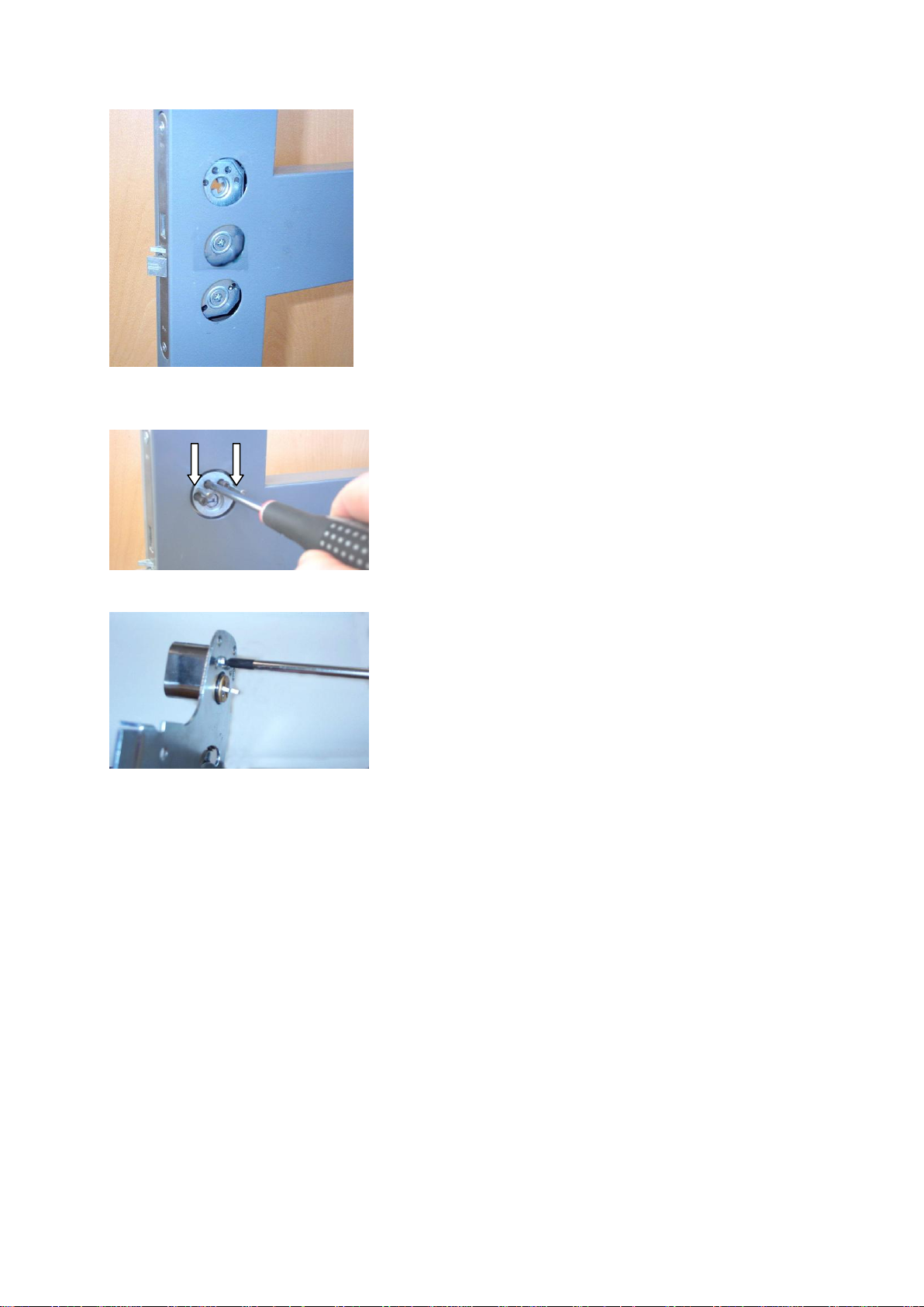
With these lock cases ASSA 1125 can be installed together with following outside modular
profile accessories:
- Accessory set ASSA 3325, ordering no 354565, including outside round cylinder cover and
handle.
- Accessory set ASSA 3425, ordering no 354564, including outside round cylinder cover and
cover plate for handle position.
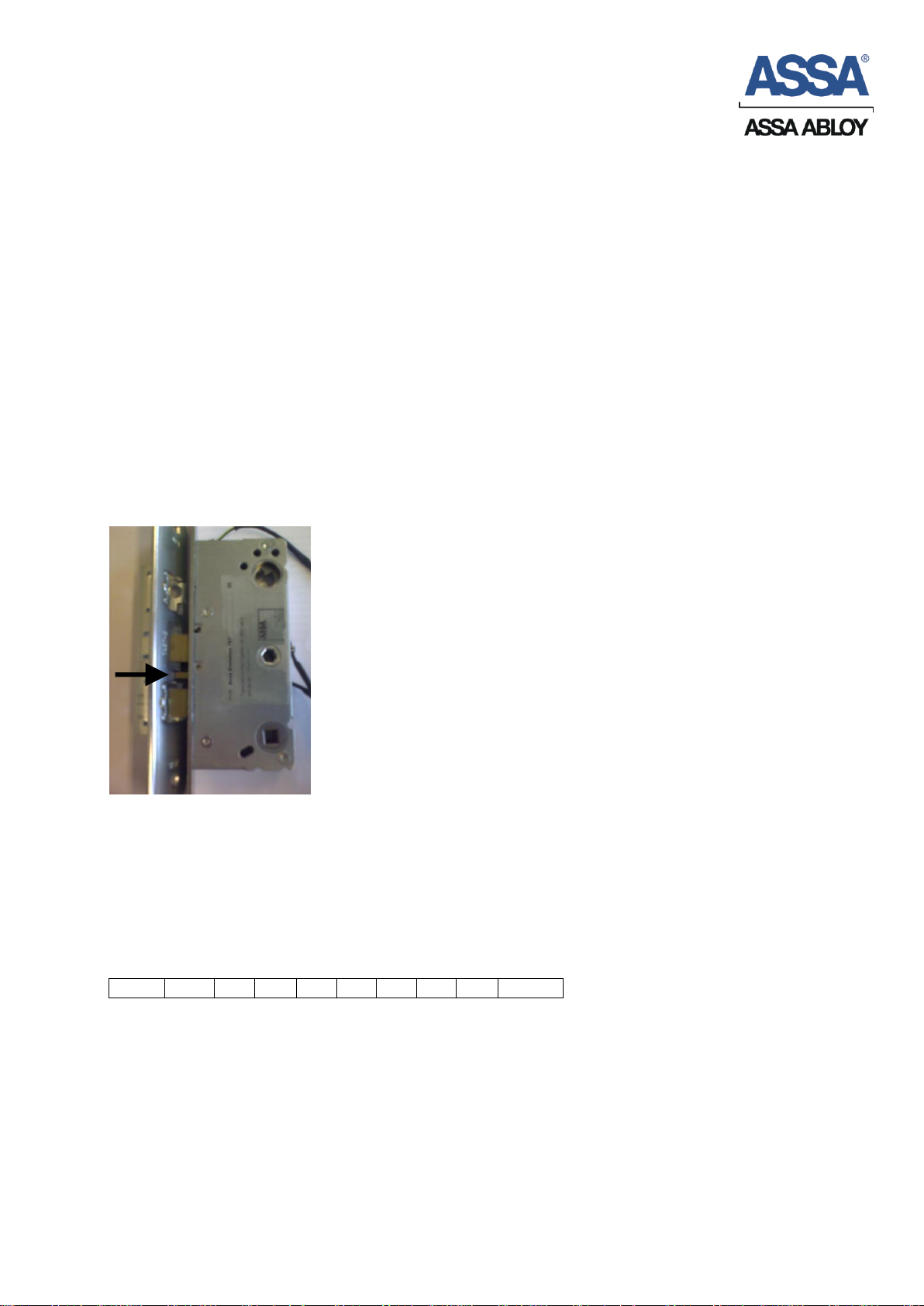
ASSA 1125 must be installed together with ASSA strike plate model 1264 1-8 with following
ordering numbers: 357207, 357208, 357730, 357732, 357728, 357729, 357731 and 357733.
Model 1487 1-5 with ordering numbers: 357545, 357546, 357547, 357547 and 357548.
Model 2530-50/70 with ordering numbers: 363759, 363760, 363761, 363762, 363763,
363764, 363765 and 363766.
Warning!
The safety features of this product are essential to its compliance with EN 1125.
No modification of any kind, other than those described in these instructions, are permitted.
ASSA takes no responsibility for products not mounted as described in these instructions or if
enclosed maintenance and operating instruction not are followed.
Classification according to EN 1125:2008
1
2
3
4
5
6
7
8
9
10
3
6
6
B
1
3
2
2
B
A
1)
(3) suitable for use in high frequency applications;
2)
(6) tested to 100 000 cycles;
3)
(6) for a door mass of up to 200 kg,
door width ≤1320 mm, door height ≤2520 mm;
4)
(B) suitable for use on fire/smoke resisting door assemblies;
5)
(1) safe for use on escape route doors;
6)
(3) high corrosion resistance;
7)
(2) grade 2 security level 1000 N;
8)
(2) horizontal bar projection of up to 100 mm;
9)
(B) "touch-bar" type B of panic exit device;
10)
(A) suitable for use on a single door and double door: active leaf only.
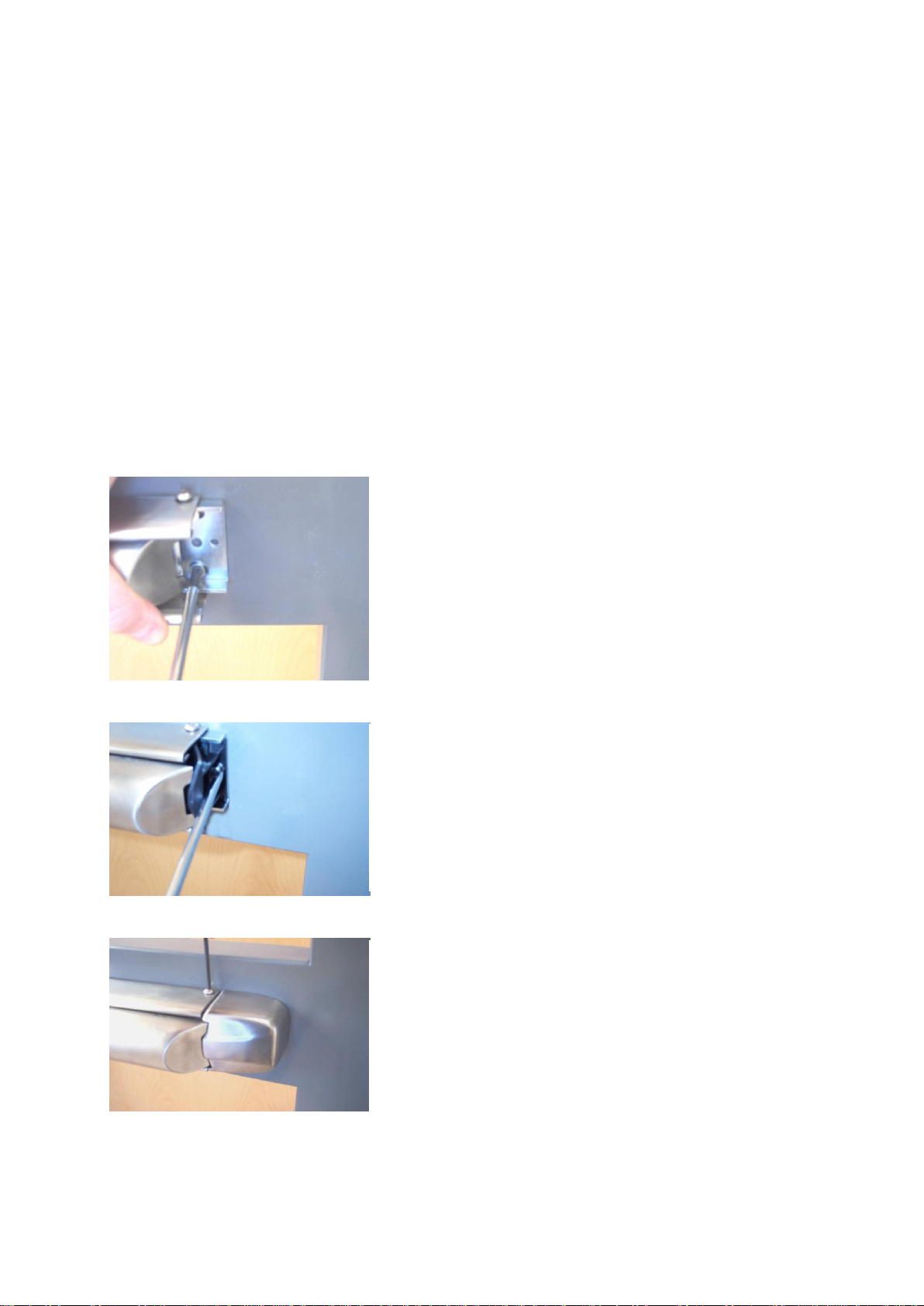
Important!!
Make sure that the deadlocking latch hits
the beam on the strike before you close
the door.

ASSA AB 091189
Utgåva / Edition 5 Sida / Page 9 / 15 160824
1. Install the lock case. The six-sided follower shall
be turned against the panic device. The gap
between door and frame shall be 1-3 mm to
insure a proper function.
Install the strike plate.
Make sure that the latches and the strike plate are
well lubricated and operate smoothly.
1.
2. Outside cylinder is fixed by four high security bolts
through the round mounting piece.
The two steering pins are, if necessary, cut according to
the table below and pressed into the mounting piece.
3. Cut the inside cylinder follower according to the table
below. Attach the cylinder to the central unit bottom
plate with two 13 mm screws.

ASSA AB 091189
Utgåva / Edition 5 Sida / Page 10 / 15 160824
C-measure
of door
Length of cylinder
follower
0 / -1 mm
Length steering pin
± 2 mm
Stop washer/six-sided
follower
C-measure
16,5 mm
4 mm
20 mm
12 mm
20 mm
7 mm
20 mm
17 mm
25 mm
12 mm
20 mm
22 mm
30 mm
17 mm
30 mm
27 mm
35 mm
22 mm
30 mm
32 mm
40 mm
27 mm
30 mm
37 mm
45 mm
32 mm
30 mm
42 mm
50 mm
37mm
46 mm
47 mm
55 mm
42 mm
46 mm
52 mm
4. Use the circular tube tool and adjust the stop washer
on the six-sided follower according to the table below.
Put the adjusted six-sided follower into the lock case
with the stop washer against the cylinder follower on the
lock case.
Two lengths of the six-sided follower are enclosed in the
package to suit different door thickness. The follower
must if necessary be cutted.
C
5. The stop washer must be turned against the central
unit to prevent the six-sided follower to slip out from the
lock case.
6. Attach the central unit. Pay attention to the connection
between the cylinder follower and the mounting piece
and between the six-sided follower and the lock case.
During installation the ball-and-socket joint must be
turned against the direction of the panic bar.

ASSA AB 091189
Utgåva / Edition 5 Sida / Page 11 / 15 160824
8. Attach the panic bar to the central unit with one Allen
screw.
7. Check the function from in- and outside cylinder:
- Function of dead bolt through in- and outside cylinder.
- Retraction of latch and deadlocking through in- and outside cylinder.
10. Connect the ball-and-socket joint between the panic
bar and the central unit. Secure the ball-and-socket joint
with the lock clip.
9. Remove the pre-mounted manipulation protection
from the rear mounting bracket, place the push bar in a
horizontal position and attach the rear mounting bracket
firmly with one screw to the door.

ASSA AB 091189
Utgåva / Edition 5 Sida / Page 12 / 15 160824
11. Check following functions:
- Opening by panic bar minimum five times. When lock case with hook bolt is
used; hook bolt shall be in a locked position while testing.
- Deadlocking of dead bolt/latch/latches
If necessary, adjust the link arm like this:
-No deadlocking/mechanism to hard:
Turn the socket joint on the link arm clockwise.
-Not fully retracted latch/to short movement on the link arm:
Turn the socket joint on the link arm anti-clockwise.
12. Attach the rear mounting bracket to the door with both
screws.
13. Attach the plastic manipulation protection to the
bracket.
14. Attach the rear cover and the panic bar to the rear
bracket with two Allen screws.

ASSA AB 091189
Utgåva / Edition 5 Sida / Page 13 / 15 160824
15. Attach the outside accessory; handle or cover plate.
When handle is used, se picture how spindle and spindle
spring is to be installed.
17. Attach enclosed after glowing stripe on the push bar.
18. Test the function again according to point 11.
16. Attach front cover and panic bar with four Allen
screws.

ASSA AB 091189
Utgåva / Edition 5 Sida / Page 14 / 15 160824
Maintenance and operating instruction for panic exit
device ASSA 1125
Panic exit device
Regular intervals of at least: One month
Check all fastenings, screws etc and that the panic bar operates in good order.
Open the door by pressing the panic bar. Ensure that the latch moves freely and get a god
engagement in the strike plate when the door is closed. The panic bar shall easily return to its
starting position after closing.
If outside handle is connected, also check the re-entry function after opening by the panic bar.
Check that the after glowing stripe is undamaged and well visible. Replace with a new stripe
if necessary.
Lock case
Regular intervals of at least: Six months
Lubricate both sides of latch and dead bolt at installation and there after every six month.
Use quality grease with high adhesive capacity, such as ASSA Lock Grease or similar.
Strike plate
Regular intervals of at least: Six months
Lubricate the sliding surface between strike plate and latch at installation and there after every
six month.
Use quality grease with high adhesive capacity, such as ASSA Lock Grease or similar.
The gap between door and frame shall be 1-3 mm to insure a proper function. Adjust if
necessary.
Lock cylinder
Regular intervals of at least: Six months
Cleaning and lubricating is recommended before summer and winter.
Use ASSA Lock Spray for lubrication.
At high frequency use or hard environment a shorter period of maintenance is recommended.
Warning! Never use oil or graphite lubricants in a lock cylinder.

ASSA AB 091189
Utgåva / Edition 5 Sida / Page 15 / 15 160824
Table of contents
Languages:
Other Assa Abloy Indoor Furnishing manuals
Popular Indoor Furnishing manuals by other brands

Seconique
Seconique Corona 4 Door 1 Drawer Sideboard Assembly instructions

Crate&Barrel
Crate&Barrel Beaumont Assembly instructions

Ryvyr
Ryvyr SELLA V-SELLA-60MXX installation instructions

Homestead
Homestead Entryway Bench manual

Dorel Home Products
Dorel Home Products DA6297 Instruction booklet

overstock
overstock CI-60 quick start guide