8
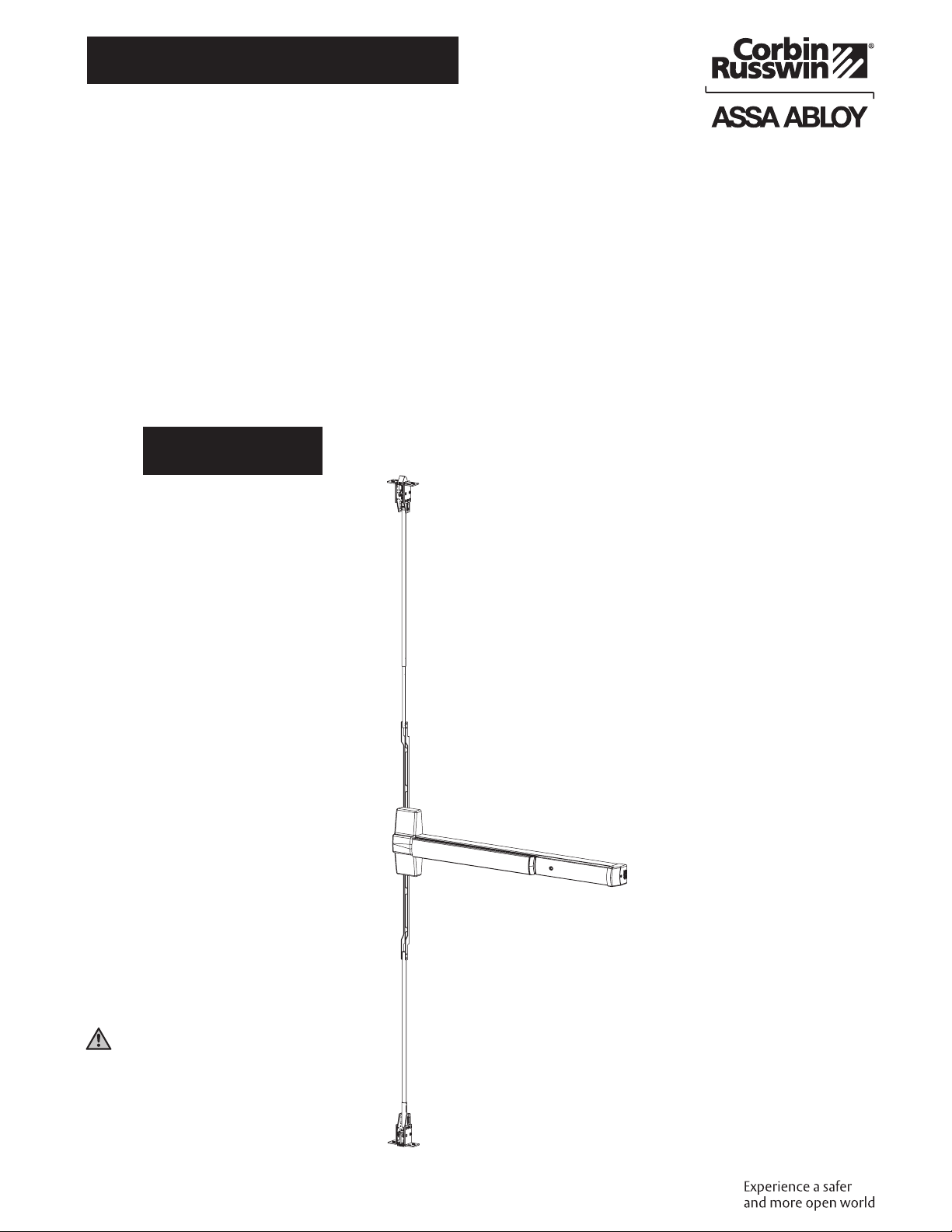
ED5860 (B) Series
Installation Instructions
Exit Device
FM544 02/20
For installation assistance contact Corbin Russwin
1-800-543-3658 • techsupport.corbinrusswin@assaabloy.com
Copyright © 1998, 2020 ASSA ABLOY Access and Egress Hardware Group, Inc. All rights reserved. Reproduction in whole
or in part without the express written permission of ASSA ABLOY Access and Egress Hardware Group, Inc. is prohibited.
5 Pre-Installation (continued)
d Prepare Door, Frame and Sill
1. Locate device paper template aligning
VERTICAL REFERENCE and HORIZONTAL
REFERENCE lines on door and template. Tape
template to door face. (Figure 7)
2. Extend centerline of rod and strikes from
device paper template to door top and
bottom, on door face.
3. Locate top strike and bottom strike templates,
aligned on centerline of rods and strikes on
door.
4. Tape templates in place and mark holes.
(Figure7)
Note:
Auxiliary door marker is included to verify
correct door preparation. Reinforced doors
and frames, with factory made cutouts, are
recommended.
5. Locate and tape trim template to door.
(See instructions packed with trim)
6. Mark and prepare holes per installation
template.
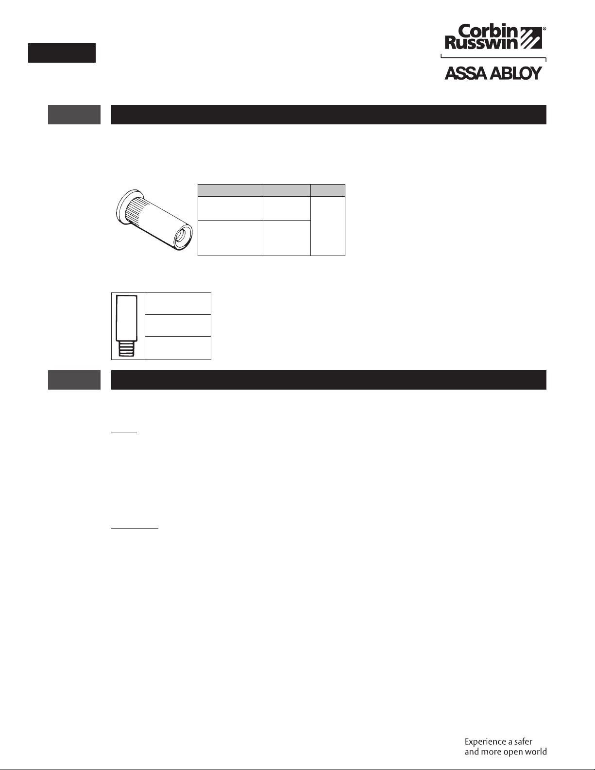
Device and Bolt Case Plates: Use two (2) 1/4-20
machine screws for metal reinforced doors OR
two (2) 3/8"(10) diameter sex nuts and bolts for each.
Top Strike: Use two (2) 10-24 machine screws.
Note:
Third screw MUST ONLY be used to lock strike in final position (See "Rod Assembly and Preliminary
Adjustment" Step 7).
Bottom Strike: 5/8"(16) diameter x 3/4"(19) deep hole.
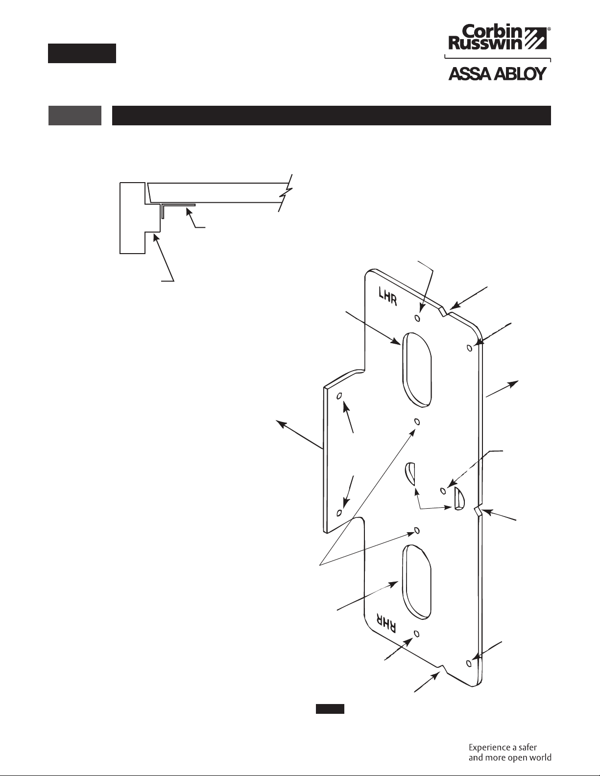
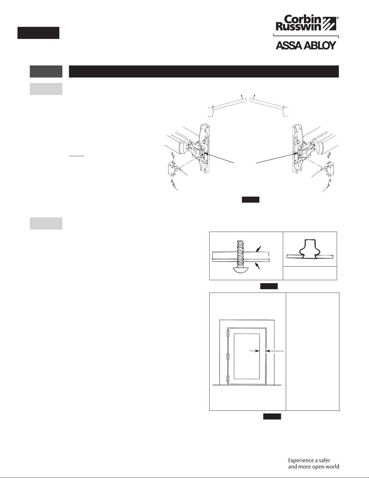
e Size Device
Device must be field cut to size, unless standard
opening and device are 36"(0.91m). (Figure8)
LHR Door Open 90˚ Inside Face
C
L
Figure8
Align mounting holes in door
with mounting holes in device.
Align horizontal line on door
with edge of device.
Verify that there is
no gap between
end cover &
touch bar prior to
marking cutoff.
Mark cutoff line.
Cut square on line.
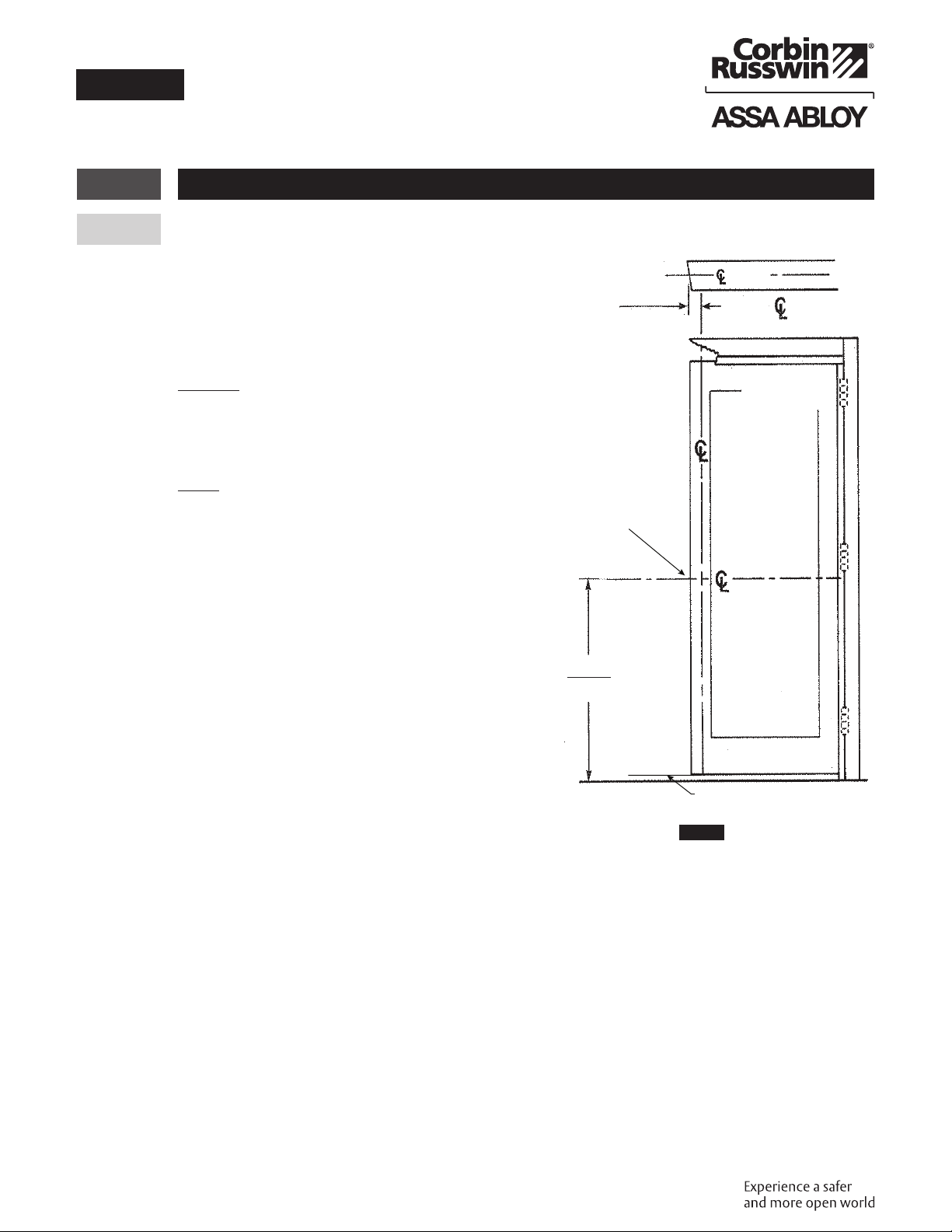
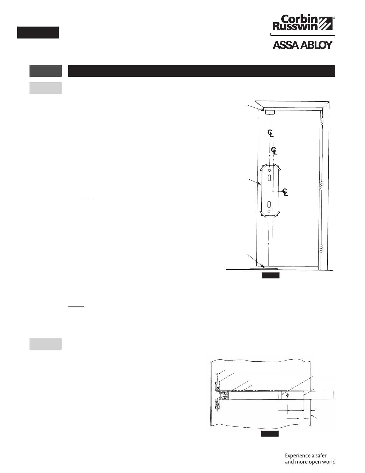
Figure7
Centerline Vertical
Reference
Centerline Rods &
Strikes
LHR Door Inside Face
Finished Floor
Centerline
Horizontal
Reference
Top Strike Template
(Mounts on Frame
Rabbet)
Floor Strike Tem-
plate (Mounts on
Finished Floor
Device Paper
Template