Assicontrol MP-2000 User manual

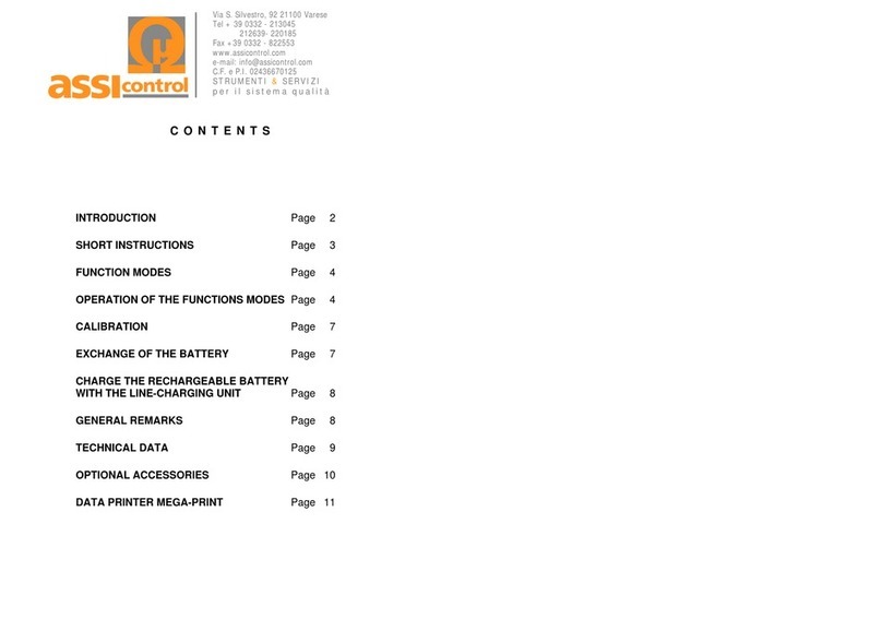
Table of contents
MP - 2000
X / 2009
INTRODUCTION Page 2
FAST START Page 4
FUNCTIONS OF THE OPERATING KEYS Page 4
IMPORTANT NOTES Page 5
1. Retention of the stored measured values
when changing the battery Page 5
2. Power supply Page 5
3. Checking the batteries or rechargeable batteries
4. Automatic power-off Page 5
5. Changing the probe Page 5
6. Battery check Page 5
I. MENU OPERATION Page 6
1. DC / AC / PEAK selection Page 6
2. Display settings Page 7
3. Memory settings Page 8
4. Print & PC settings Page 9
5. Setting options Page 10
II. MEASURING PROBES Page 12
III. CHECKING WITH THE PRECISION
CALIBRATION STANDARD Page 13
IV. OPERATION WITH THE PRINTER Page 13
V. INTERFACE SETTINGS Page 13
VI. SOFTWARE Page 14
TECHNICAL DATA Page 15
MEGA-PRINT DATA PRINTER Page 16
INTERNET SURVEY Page 17
STRUMENTI &SERVIZI
per il sistema qualità
V
ia S. Silvestro, 92 21100 Varese
Tel + 39 0332 - 213045
212639- 220185
Fax +39 0332 - 822553
www.assicontrol.com
C.F. e P.I. 02436670125

2
INTRODUCTION
You have chosen the
MP -2000
magnetic field meter and you have done so for a good reason, because you have
bought a device that is not only designed and manufactured according to the state of
the art, but is above all light and convenient to operate.
The devices are manufactured exclusively in Germany.
We have made every effort to make this operating manual as short and as clear as
possible.
Nevertheless, if you should have any questions about operation, please contact our
competent service technicians, who are always ready to help. They will be pleased to
assist you.
Which magnetic fields can the MP-2000 measure?
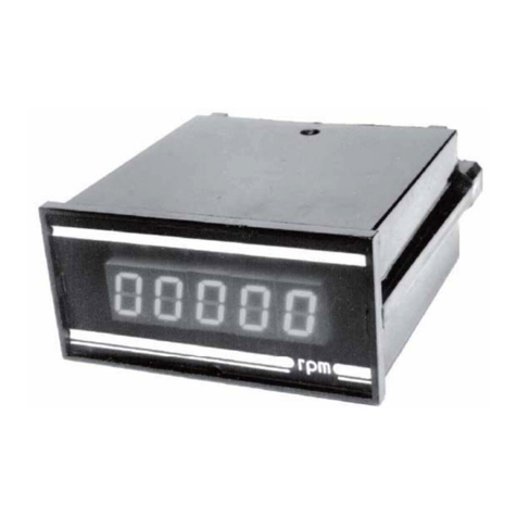
The MP-2000 field meter measures all practically occurring magnetic fields, both DC
and AC, in a range from 0.1 to 40,000 A/cm (Oersted).
The device has two measurement ranges:
0 - 199.9 A/cm (Oersted)
200 - 40,000 A/cm (Oersted) DC / 200 - 20,000 A/cm(Oersted) AC
( 1 A/cm = 0.1 kA/m = 1.256 Oe(Gauss) = 0.1256 mT)
Measurement range switching takes place automatically.
The measuring unit can be switched between A/cm – kA/m - Gauss – mT.
DC fields, AC fields (effective value RMS) or peak value are displayed with storage.
Either a P-T2 / PT-4 tangential field probe, a P-A2 / P-A4 axial field probe or the spe-
cial P-Z2 / P-Z4 reed probe (0.7 mm thick) can be connected to the device.
A calibration standard is available on request for checking the calibration of the de-
vice.

3
And what is really unique:
For the first time, the MP-2000 uses measuring probes in which an integrated micro-
controller digitises and linearizes the special analogue signals directly in the probe.
This new technique is highly immune to interference and permits extremely precise
measurements even with high magnetic field strengths, where Hall probes no longer
operate linearly.
The built-in rapid peak value memory can measure pulse fields down to 0.1 msec.
In this device, the probe cable is pluggable at both ends (display device and probe)
and is therefore particularly service-friendly, because the customer can simply replace
the cable in the event of a cable breakage.
The convenient menu operation in several languages allows simple operation of the
device for the most part without an operating manual.
The MP-2000 offers the possibility to create up to 100 measurement storages (total
memory capacity: 10,000 measured values). Statistical evaluation takes place either
on the display or by connecting a printer or PC.
In addition to that, the MP-2000 has an analogue display with automatic measuring
range selection in order to quickly visualise changes or tendencies in magnetic fields.
For evaluation via a PC, a USB wireless interface is built into the device which, in
conjunction with the USB radio receiver supplied with the device, allows wireless
communication with a PC.
Various evaluation programs are available on request.

4
FAST START
•Connect the probe cable to the measuring probe and device.
•Switch on the MP - 2000 with the ON-OFF key. Automatic zero balancing
takes place when the device is switched on, therefore the probe should not be
in a magnetic field when doing so. The last measured value appears briefly on
the display, followed by the current measured value.
•To change the language (English is preset) press the MENU key:
Scroll through the menu using the arrow keys; confirm your selection using the
OK key.
FUNCTIONS OF THE OPERATING KEYS
DC/AC/PEAK
Display
Batch
Print+PC
Setup
Language
LCD-Light
Unit
Bat. Voltage
Reset
DC/AC/PEAK
Display
Batch
Print+PC
Setup
German
English
Spanish
Netherlands

5
IMPORTANT NOTES
1. Retention of the Stored Measured Values when changing the Battery
The stored measured values are retained even after switching off the device or
storing it without a battery.
2. Power Supply
The device is supplied as standard with three 1.5 V (Mignon) batteries. However, it
can optionally be powered by three 1.2 V NiCd rechargeable batteries. A suitable
charger is available from the factory and is connected to the serial interface.
Charging time: 8 – 10 hours.
The charger can also remain permanently connected!
3. Checking the Batteries or Rechargeable Batteries
The batteries must be replaced or the rechargeable batteries charged up as soon
as only 1 bar appears on the battery display when the device is switched on. If the
message ‘replace batteries’ additionally appears on the display, then the device
switches itself off automatically for protection if the battery voltage is too low. The
exact battery voltage can additionally be displayed for checking purposes:
The battery voltage should be greater than 3.0 V!
Used batteries are special waste and must be disposed of accordingly!
7. Automatic Power-Off
The device switches itself off automatically 2 minutes after the last measurement if
the measured value does not change.
8. Changing the Probe
To change the measuring probe, switch off the device first, connect the desired
measuring probe to the probe cable and then switch on the device again. If no
measuring probe is connected to the device, or if the probe cable has no connec-
tion to the device, a message is displayed when the device is switched on and the
device switches itself off again automatically.
DC/AC/PEAK
Display
Batch
Print+PC
Setup
Language
LCD-Light
Unit
Bat. Voltage
Reset
DC/AC/PEAK
Display
Batch
Print+PC
Setup

6
I. MENU OPERATION
-0- key – Zero Point Setting
Zero point adjustment takes place after pressing the -0- key. The probe must not be
in a magnetic field during this time! After the zero balancing is complete, the display
shows
±
0.2 (influence of the earth’s magnetic field when moving the measuring
probe).
MEM key – Save Measured Value
After pressing the MEM key, the current measured value is saved in the selected
batch memory.
MENU Key
The various functions of the device are controlled via a menu. After switching on the
device, press the MENU key in order to call up the menu.
The arrow keys are used to select the menu item; the current selection has a black
background. The selected menu item is called up via the OK key; either a sub-menu
or the selected device function appears.
The Ckey is used to quit the device menu; the main menu field is selected with the
central blue key.
1. DC / AC / PEAK Selection
DC Field
Switch to the DC steady field range in order to measure static fields. The DC symbol is
shown behind the current measured value on the display.
RMS-AC Field
Switch to the AC alternating field range in order to measure alternating fields The AC
symbol is shown behind the current measured value on the display.
In the case of sinusoidal AC fields, the respective effective value (true RMS) is displayed.
The respective conversion factors for full-wave and half-wave rectification are given in
the DIN standard 54 131 Part 1.
DC-Fields
RMS-AC Fields
PEAK Range P1
PEAK Range P2
DC/AC/PEAK
Display
Batch
Print+PC
Setup

7
PEAK Measuring Range P1 / P2
Switch to the peak value memory range P1 in order to measure peak fields < 500
A/cm (G) or < 50.0 kA/m (mT). The PEAK symbol is shown behind the current
measured value on the display. If the measurement range is exceeded, the display
shows:
You can switch to the peak value memory range P2 with the OK key; after that, re-
peat the measurement!
Switch to the peak value memory range P2 in order to measure peak fields >= 500
A/cm (G) or >= 50.0 kA/m (mT). If no peak value is displayed in the peak value
memory P2, this means that the peak value is < 500 A/cm (< 50 kA/m); in this case
select the peak value range P1!
If there is already a measured value in the peak value memory and a higher meas-
ured value is recorded, then the old measured value will be overwritten by the new
one. A short acoustic signal is sounded when the measured value is exceeded.
The peak value memory is reset via the -0- key.
When measuring AC fields in peak value memory mode, the peak value and not the
effective value will be saved if the AC field is sinusoidal!
2. Display
The various display functions of the MP - 2000 can be selected here (Digital /
Statistics / Analogue). The operation is as follows:
•Digital:
The normal digital display is activated as standard. The current measured value
is displayed here. Press once the right hand blue MEM key to save the current
measured value in the batch memory. Zero setting is carried out via the -0- key.
PEAK-Value >
Switch Range:
Confirm – Key ‚OK’
Cancel – Key ‚C’
DC/AC/PEAK
Display
Batch
Print+PC
Setup
Digital
Statistic
Analogue
-0- MENU MEM
DC
100.5 N
A/cm

8
100.5 DC
A/cm
Batch-No.: 1 No.: 200
Min: 50.0 A/cm
Max: 349 A/cm
Mean: 199 A/cm
Std.Dev.: 87.0 A/cm
0.5
A/cm
•Statistics:
When the statistics display is activated, the current measured value is displayed
at the top and the statistical parameters are additionally displayed. Press once
the right hand blue MEM key to save the current measured value in the batch
memory. Zero setting is carried out via the -0- key.
To delete the last measured value, select MENU – Memory – Delete – Delete
last value.
•Analogue:
After activating the analogue display, the start of the measuring range is input
first (min. value), after which the analogue display is shown in the centre on the
display with the preselected start of the measuring range. The maximum meas-
uring range value is automatically adjusted according to the size of the current
measured value.
Press once the right hand blue MEM key to save the current measured value in
the batch memory. Zero setting is carried out via the -0- key.
3. Memory:
The MP–2000 contains a maximum of 100 different application memories for the
saving and statistical evaluation of object-related series of measurements.
A maximum of 10,000 measurements can be saved in all. The maximum number
of measurements per application memory depends on the number of memories
created.
First of all the required number of memories should be selected, after which the
current memory number in which the measured values should be saved is acti-
vated in the Display/Select sub-menu. The operation of the individual memory
options is as follows:
-0- MENU MEM
DC/AC/PEAK
Display
Batch
Print+PC
Setup
Digital
Statistic
Analogue
-0- MENU MEM
DC/AC/PEAK
Display
Batch
Print+PC
Setup
Digital
Statistic
Analogue
Analog
Min-Wert: 0.0 A/cm

9
•Display / Select:
The memory contents are displayed or the current memory is selected here. At
the same time, any measured value in the memory can also be deleted here,
upon which the statistics will be automatically updated.
Any measured value can be selected using the arrow keys (measured value no.
has a black background) and the selected measured value is deleted using the
centre blue key if required. The memory number is selected using the left and
right blue keys.
•Memory:
Here you can delete either the last measured value from the current batch mem-
ory, all stored measured values in the currently set memory or all measured val-
ues in all memories.
•Select max. number:
The required number of batch memories is selected here; the max. number of
measured values that can be saved per memory is displayed at the same time.
4. Print + PC
This menu item serves exclusively to send the stored measured data via the se-
rial interface to the MEGA-PRINT printer or via the USB wireless interface to the
PC.
In addition there is a possibility to send the current measured value to the PC
every 0.5 sec. in combination with our STAT-6 or TRANSFER-EXCEL program
for the evaluation of measurement curves.
Batch-No. 1
Min.: 31.0 A/cm
Max.: 130 A/cm
Mean: 80.5 A/cm
Std.Dev.: 29.0 A/cm
No. 30 - 130 A/cm
< CL >
DC/AC/PEAK
Display
Batch
Print+PC
Setup
Display / Select
Delete
Max.Batch-No.
Clear last Value
Clear actual Batch
Clear all Batches
DC/AC/PEAK
Display
Batch
Print+PC
Setup
Display / Select
Delete
Max. Batch-No.
DC/AC/PEAK
Display
Batch
Print+PC
Setup
Display / Select
Delete
Max. Batch-No.
Batch
Batch 10
Numbers 1000

10
•Send to PC:
Send the statistical evaluation & measured values from the current memory to
the PC via the USB wireless interface and our serial interface. Start the data
transfer in the PC program first!
•Print Measured Values:
Transfer the statistical evaluation & measured values from the current memory to
the MEGA-PRINT printer.
•Print All Memories:
Transfer all measured values and statistics from all selected memories to the
printer.
Caution: this option should only be selected if there are not too many memories or
if there are not many measured values stored in the memories, as otherwise the
printer’s paper consumption will be very high and the data transfer will take a very
long time!
•Current Transfer:
If this function is activated, the current measured value will be sent to the USB
wireless interface and the serial interface every 0.5 sec.
DC/AC/PEAK
Display
Batch
Print+PC
Setup
Print+PC
Send to PC
Send to PC
Print Values
Print all Batches
Current Transfer
Print+PC
Print Values
DC/AC/PEAK
Display
Batch
Print+PC
Setup
Send to PC
Print Values
Print all Batches
Current Transfer
Send to PC
Print Values
Print all Batches
Current Transfer
DC/AC/PEAK
Display
Batch
Print+PC
Setup
Print+PC
Print all Batches
DC/AC/PEAK
Display
Batch
Print+PC
Setup
Send to PC
Print Values
Print all Batches
Current Transfer
Print+PC
Off
On

11
5. Setting - options
•Select Language:
•
•Switch LCD Lighting on/off:
Off: Switch off LCD lighting
On: LCD lighting always switched on
Auto: LCD lighting is switched on for approx. 2 sec. during the measurement
and when a key is pressed; after that it switches off to save the battery.
Note: The battery lifetime will be shortened considerably if the LCD
lighting is always switched on! The LCD lighting switches itself off
automatically at a battery voltage of 2.9 V or less in order to save
the battery!
•Select measuring unit (Gauss – mT – A/cm – kA/m switching):
( 1 A/cm = 0.1 kA/m = 1.256 Oe(Gauss) = 0.1256 mT)
•Display battery voltage:
The battery voltage should be greater than 3.0 V!
Language
LCD-Light
Unit
Bat. Voltage
Reset
DC/AC/PEAK
Display
Batch
Print+PC
Setup
Deutsch
English
Spanisch
Niederlande
DC/AC/PEAK
Display
Batch
Print+PC
Setup
Language
LCD-Light
Unit
Bat. Voltage
Reset
Setup -
LCD-Light
Off
On
Auto
DC/AC/PEAK
Display
Batch
Print+PC
Setup
Language
LCD-Light
Unit
Bat. Voltage
Reset
Setup -
Unit
Gauss
mT
A/cm
kA/m
Language
LCD-Light
Unit
Bat. Voltage
Reset
DC/AC/PEAK
Display
Batch
Print+PC
Setup
Setup -
Bat. Voltage
4.20 V

12
•Reset:
Reset returns all device settings to the factory settings. This function should be
used if settings have been changed and the device does not work properly or if
the calibration of the probe does not work properly.
II. MEASURING PROBES
Either a P-T2 / PT-4 tangential field probe, a P-A2 / P-A4 axial field probe or the spe-
cial P-Z2 / P-Z4 reed probe (0.7 mm thick) can be connected to the device. These
are distinguished by their design and measuring range as follows:
Table of available measuring probes:
Probe type Measuring range
[A/cm / Gauss] Dimensions
Axial field probes
P-A2
P-A4
0 – 20.000 A/cm / Gauss
0 – 40.000 A/cm / Gauss
Tangential field
probes
P-T2
P-T4
0 – 20.000 A/cm / Gauss
0 – 40.000 A/cm / Gauss
Reed probes
P-Z2
P-Z4
0 – 20.000 A/cm / Gauss
0 – 40.000 A/cm / Gauss
(1 A/cm = 0.1 kA/m = 1.256 Oe(Gauss) = 0.1256 mT)
A calibration standard is available on request for checking the calibration of the de-
vice.
Setup -
Instrument-Reset
Reset
DC/AC/PEAK
Language
LCD-Light
Language
LCD-Light
Language
LCD-Light
Unit
Bat. Voltage
Reset

13
III. CHECKING OF THE MP-2000 WITH THE PRECISION CALI-
BRATION STANDARD:
It is not necessary to calibrate the device. The measuring probes are pre-calibrated
and are interchangeable.
A precision calibration standard with 180 A/cm is optionally available in order to
check the device with a measuring probe.
Tangential field probe:
Insert the probe, with the lettering N = north pole pointing upwards, into the slot of the
calibration standard until the probe latches at the front. Compare the displayed value
with the value of the calibration standard.
Axial field probe:
Insert the probe vertically into the cut-out with the red recess of the calibration stan-
dard and rotate it until the maximum value is displayed. Compare the displayed value
with that of the calibration standard.
IV. OPERATION WITH THE PRINTER
The device’s interface parameters have been set in the factory so that the MEGA-
PRINT data printer available from us can be connected without having to change the
interface parameters.
Operating instructions
1. Connect the printer cable to the device socket (RS 232C) and the printer.
2. Switch on the MP-2000; the printer then switches on automatically.
3. See menu operation item 4 – Transfer & PC
V. INTERFACE SETTINGS
The device’s interface parameters are set as standard for the USB wireless interface.
The USB interface driver included in the software must be installed so that a virtual
COM port can be assigned to the USB interface. If necessary you can check under
System Settings – Device Manager which COM port number is being used by the
USB interface so that you can set the correct COM port in the software.

14
VI. SOFTWARE
TRANSFER data read-in program
The TRANSFER read-in program runs under Windows XP and Vista 32-bit. It reads
the measured values into a file and displays them on the screen. Refer to the soft-
ware instruction manual for more details.
TRANSFER-EXCEL data transfer program
This program automatically reads the measured values into an existing Excel file.
STAT-6 statistics program
This specially developed program features a graphical evaluation of the measured
values as a bar and line chart with statistical evaluation and runs under Windows XP
and Vista 32-bit.
You can also measure online using the STAT-6 program in conjunction with the MP -
2000. The current measured value is shown in large characters on the screen so that
you can follow all measured data and the entire course of the test. Refer to the soft-
ware instruction manual for more details.

15
TECHNICAL DATA
Model MP - 2000
Display: Illuminated graphics display:
Measuring units: kA/m – A/cm – Gauss(Oe) – Tesla
selectable
Measuring ranges: DC: 0 – 4000 kA/m
DC: 0 – 40.000 A/cm (Gauss/Oe)
DC: 0 – 4000 mT
AC: 20 – 20.000 A/cm (Gauss/Oe)
AC: 20 – 2000 kA/m
AC: 20 – 2000 mT
Automatic measuring range selection
Resolution:
0 – 200 A/cm (Gauss): 0.1 A/cm (G)
> 200 A/cm (Gauss): 1 A/cm (G)
> 10,000 A/cm (Gauss): 1 kA/m (G)
0 – 20 kA/m (mT): 0.01 kA/m(mT)
> 20 kA/m (mT): 0.1 kA/m (mT)
> 1000 kA/m (mT): 1 kA/m (mT)
Accuracy (in homogeneous field) DC/AC range - 0-2000 kA/m ±2 %
> 2000 KA/m ±3 %
AC frequency range:
(AC = effective value RMS) 10 Hz – 5 KHz
Peak value memory (PEAK HOLD): Impulse duration > 0.1 msec.
For use with measuring probes: Axial and tangential field probes:
P-A2 / P-T2 / P-Z2
P-A4 / P-T4 / P-Z4
(see Page 12)
Power supply: 3 x 1.5V AA Mignon,
alternatively 3 x 1.2V AA rechargeable
Operating time: Approx. 100 hrs.
Automatic switch-off: 2 min. if no change in measurement
Battery indication: X
Measurement store: 10,000
measurements
Applications memory: max. 100
Multilingual menu navigation X
Statistical evaluation (MAX. MIN. MEAN.
NO. STD.DEV. X
Display of statistics and stored measure-
ments: X
Analogue & digital measured value display
with automatic range selection: X
RS232 interface: X
Radio –USB interface: X
Dimensions: 198 x 92 x 35 mm
Weight with batteries: 265 g
Warranty: Display device: 12 months
Measuring probe: 3 months

16
MEGA-PRINT DATA PRINTER
Technical data
Printing method: Thermal printer
Characters/line: 20
Transfer speed: 1200 baud
Printing speed: Max. 20 lines/sec.
Interface: Serial
Paper: Thermal paper 57 mm wide – max. 10 m long
Power supply: Ni-Cad rechargeable battery
(approx. 60 hours of operation per charge)
Dimensions: 110 x 80 x 45 mm
Weight 240 g
Mains charger: 230 V/50 Hz / 6.0 V – 0.5 A
Charging the built-in Ni-Cad rechargeable battery
When delivered new, the Ni-Cad rechargeable battery in the MEGA-PRINT must
be charged up before first-time use.
The built-in Ni-Cad rechargeable battery is charged up with the mains charger sup-
plied. The cable from the mains charger is plugged into the connection socket on the
right hand side.
The charging time should be at least 4 hours.
The green LED blinks during the charging process; it lights steadily when the battery
is fully charged. The charger then switches automatically to maintenance charging
mode.
The capacity of the rechargeable battery is sufficient for approx. 60 hours of opera-
tion.
Notes on operation
1. The operation of the MEGA-PRINT printer in conjunction with the MP-2000 mag-
netic field meter is explained under Menu Operation item 4 – Transmit & PC in the
MP-2000 operating manual.
2. The printer is switched on automatically when the connecting cable between the
MP-2000 and the MEGA-PRINT is connected (the green LED blinks every 2 sec).
If the meter is switched off, the MEGA-PRINT also switches off automatically (the
green LED remains off).
3. The paper is manually transported using the ‘Paper feed’ button. After completion
of the printout, the paper strip is transported out of the housing by pressing this
button and can then be cut off cleanly.

17
4. Faulty printout
The MEGA-PRINT must be charged up again if individual lines of the printout are
not printed correctly.
Inserting a new paper roll
•Open the cover
•Insert the paper roll
•Pull out the end of the paper
•Close the cover
Table of contents
Other Assicontrol Measuring Instrument manuals
Popular Measuring Instrument manuals by other brands

Ludlum Measurements
Ludlum Measurements 26-2 user manual

SONBEST
SONBEST SM2120B user manual

mru
mru AirFair OPTIMA 7 NDIR user manual

Test Equipment Depot
Test Equipment Depot DM8200 user manual

Endress+Hauser
Endress+Hauser Gammapilot M FMG50 Brief operating instructions

Ziegler
Ziegler 3410 quick start guide