AST PCH GMP-025 Series User manual

PCH GMP-025 SERIES
INSTRUCTIONAL MANUAL
1600 FREEWAY BLVD.
BROOKLYN CENTER, MN 55430
Phone (763) 592-2060
Fax (763) 592-2075
Web www.ast-corp.net
E-Mail ast
@
ast-cor
p
.net
MODEL
PCH GMP-025-1616
RATIO
1:1
MANUFACTURED FOR
________________________________
SERIAL NUMBER
________________________________
OPERATING INSTRUCTIONS
I. AST Warranty
II. General Description of System, with Diagrams
III. Unpacking, Set-up and Pre-Start Checks
IV. Daily Operation
V. Periodic Maintenance
VI. Trouble Shooting
VII. Shutdown Procedures
VIII. TEDs
IX. Bills of Material/Drawings
#60005-02 REV: 07/18

CONTENTS
INTRODUCTION
WARRANTY INFORMATION 1
TECHNICAL VIDEOS 1
CUSTOMER SERVICE 1
GENERAL DESCRIPTION OF SYSTEM
INLET ASSEMBLY 2
ELECTRICAL DRIVE MOTOR 3
GEAR METERING PUMPS & OUTLETS 3
DELIVERY HOSES 4
DISPENSE VALVE 4
STATIC MIXER 4
ELECTRICAL & PNEUMATIC CONTROLS 5
UNPACKING, SET-UP & PRE-START CHECKS
SET-UP & PRE-START CHECKS 6
TIPS, PRECAUTIONS & WARNINGS 6
DAILY OPERATION
START-UP 7
SHUT-DOWN 7
PERIODIC MAINTENANCE
METERING PUMP MAINTENANCE 7
DISPENSE VALVE MAINTENANCE 7
RATIO CHECK 7
SHUT-DOWN PROCEDURES
PUMP CLEANING PROCEDURE 10
SHORT-TERM SHUT-DOWN PROCEDURE 10
END OF SEASON SHUT-DOWN PROCEDURE 11
TECHNICAL ENGINEERING DATA SHEETS
TEDs 13
BILLS OF MATERIAL/DRAWINGS
DRIVE ASSEMBLY 18
ELECTRICAL SCHEMATIC 19
GEAR METERING PUMPS 20
OUTLET ASSEMBLY 21
INLET ASSEMBLY 22
EXTENSION HANDLE ASSEMBLY 23
DISPENSE VALVE 24
WHEEL ASSEMBLY 25
PUMP REPLACEMENT KITS 26
DISPENSE VALVE REPLACEMENT KIT 26
STATIC MIXER ASSORTMENT 26
DESSICANT DRYER ASSEMBLY 27
TABLE OF CONTENTS
REV: 03/10
TROUBLE SHOOTING
TROUBLESHOOTING 7
RATIO CHECK PROCEDURE 8
TROUBLESHOOTING GUIDE 9

INTRODUCTION
WARRANTY INFORMATION
AST assumes that all persons operating or working
on or with this system have read and understand
the following operating instructions.
AST /Adhesive Systems Technology Corp.
warrants that products of its manufacture and
bearing its name identification, when used in
accordance with instructions and not misused or
neglected, to be free from defects in
workmanship or materials.
This warranty does not apply to normal wear or to
damage or wear resulting from misuse, abrasion,
corrosion, negligence, accident, improper
installation or tampering.
Standard commercial components parts are
excluded from this warranty and are covered
under the original manufacturer's warranty.
AST obligation under this warranty is limited to
repairing or replacing at its distribution center any
such product or part thereof which shall within (1)
8-hour shift daily use during six months after
delivery to the original purchaser be returned to
AST, transportation charges prepaid, and which
upon examination reveals to have been thus
defective.
AST assumes no liability for consequential or
contingent damage of any kind arising out of
failure of its product, including losses caused by
defective materials and workmanship.
Damages due to causes other than defective
materials or workmanship will be repaired at
normal service charges.
AST is not responsible for labor or material
charges arising from removal or replacement of
warranted parts
This warranty is expressly in lieu of other
warranties, obligations of liability expressed or
implied by the Company or its representatives.
All statutory or implied warranties, including any
warranties of merchantability or fitness other than
title, are hereby expressly negated or excluded.
AST and its representatives may furnish, upon
request, data and services relating to the
application or use of its product. It will not be
responsible, and does not assume any liability
whatsoever for damages of any kind sustained,
either directly or indirectly, by any person in the
adoption or use of such data or services in whole or
in part.
Damages for breach of warranty are limited to the
purchase price of the product. Upon repayment of
such amount to the buyer/end user, the contract of
sale of the equipment is cancelled without
reservation of rights.
#60005-02 : Page #1
11/06
TECHNICAL VIDEOS
Each new unit includes an instructional video that
details the items in this manual. Additional or
replacement videos can be purchased through AST
CUSTOMER SERVICE
AST customer service & technical support is
available Monday-through Friday, 8AM – 4:30PM
CST. For more efficient service, have your
machine’s serial number ready (serial number can be
found on the front page of this instructional manual
AND on a silver tag mounted on the machine).
REPLACEMENT/SPARE PARTS
oOnline: www.ast-corp.net. Click “Parts/Service”
oPhone: 763-592-2060
oFax: 763-592-2075
*Same day shipment on most parts
Other services provided by AST include:
TRAINING: Factory and field training seminars available
INFORMATION: Complete service & maintenance
history records for each current system, complete
engineering & manufacturing specifications and
drawings for all equipment, and complete inventory of
consumable items are kept by AST.
SUPPORT: AST provides engineering support to work
with you in maintaining equipment and increasing
production. AST also provides system upgrade support
along with field upgrades, repair & service (both at the
factory & in the field) and preventative maintenance
p
ro
g
rams.

GENERAL DESCRIPTION OF
SYSTEM
The GMP-025 Meter-Mix-Dispense system has two
gerotor type gear metering pumps (GMP) that are
powered with an electric motor. The system consists of
seven major sections. Each of the components is
described below.
1. Inlet Assembly
2. Electrical Drive Motor & Gear Reducer
3. Gear Metering Pumps and Material Outlets
4. Delivery Hoses
5. Dispense Valve
6. Mixer
7. Controls
This system is designed for use only with the material
specified on the T.E.D. sheet for this system. Use of
other materials is not approved without explicit factory
consent and may cause poor results, damage the
system, or other problems, which is considered misuse
under AST warranty.
Each of the major sections is described below.
If supplied, the air dryer assembly (See BOM & Drawing
#55472A) consists of a desiccant canister connected by
polyurethane tubing to the bent in each tank lid. A small
window on the side of the canister allows the user to view
the contents. When the light blue to any other color, the
canister should be replaced.
NOTE: New canisters need holes punctured in each end
of the canister for the system to work properly. Failure to
do so will result in problems with the dispense ratio.
Each tank contains a screen assembly to prevent any
debris or unwanted particles from entering the pump. This
screen should be removed and cleaned periodically to
prevent blockage inside the tank.
The inlet block connects the tank/inlet assembly to the
gear pump. The block is connected by (4) 5-16”-18 x 2-
1/4” bolts. Removing these 4 bolts will allow the entire
inlet assembly to be removed from the machine.
#60065-02: Page #2
Each inlet assembly consists of a tank, lid, manual shut-
off valve, and a pump inlet block. Typically, 5-gallon
stainless steel tanks with a cone bottom are supplied
with the unit (other options are available). The tanks are
piped to the gear pump inlets. Each tank has three lid
clamps, which may require occasional adjustment to
maintain the lid seal.
Manual shut-off valves are installed between the
material tanks and the gear pumps. These valves can
be shut before servicing the pump to allow most of the
material in the tank to remain inside. The valves should
also be shut during transportation of the unit.
NOTE: Each manual shut-off valve must be open during
dispensing.
Each lid has a silicone gasket that can be scraped out
when it becomes damaged over time. The shape of the
lid allows the gasket to be re-made with any RTV
silicone. Each lid also has a vent to allow air inside the
tank as the material is pumped out. For moisture-
sensitive materials, this vent is connected to an air dryer
assembly
1. INLET ASSEMBLY

The GMP is driven by a TEFC 90 V D.C., variable speed
electric motor. The motor is fuse-protected; which is
located inside the controller. The internal gear reducer is
pre-lubed and sealed.
Two zerks for lubrication of the pump are provided. The
zerk closest to the pump shaft is provided for filling the
seal chamber. The zerk closest to the pump’s side
outlet is provided for lubrication of the metering gear
itself. Both should be filled daily with a lubricant
compatible with the material being dispensed. NOTE:
The second zerk cannot be filled without opening the
bleed port at the bottom of the pump. While the zerk on
the top of the pump is filled, the bleed valve at the
bottom of the pump must be opened. Lubrication is
complete when fresh lubricant is pushed out from the
bleed valve.
**Use caution when disassembling the Gerotor pump,
making sure not to gouge or mar any of the internal
surfaces of the pump.**
#60065-02: Page #3
Each AST gear metering pump consists of a hardened
drive shaft, lube chamber with dual shaft seals, metering
gear, material inlet block with air bleed port and a material
outlet assembly with gauge
In operation the pump shaft is connected to an inner drive
gear which, when turned, drives an outer internal driven
gear. The inner gear has one less tooth than the outer
gear allowing the pump to transfer material from the inlet
to the outlet of the pump, which are on opposite sides of
the gears. Precise tolerances prevent material by-pass as
the gears maintain a positive seal as the contours of each
gear are followed. Excessive wear or physical damage to
the surfaces of the working section of the pump will
reduce the ratio accuracy of the system.
Ratios are simply a function of the number of teeth on
either drive sprocket. Example: a 32 and a 16-tooth
sprocket will dispense at a 2:1 ratio by volume. In some
cases, dual stage pumps can be used on one side to
obtain a wider ratio.
Gauges on the outlets of the pumps allow the operator to
monitor pumping pressures. Pressure readings on the
gauges will almost always be different from “A” to “B”; this
is due to the difference in viscosities of the “A” and “B”
materials. The operator should pay attention to the
behavior over time of the gauges. Large variations often
indicate problems with obstructions, empty tanks/inlets, or
other problems.
3. GEROTOR PUMPS & MATERIAL OUTLETS
2. ELECTRIC DRIVE MOTOR & GEAR REDUCER

“A” and “B” materials flow through their individual delivery hoses. The two material hoses plus control air lines join the
main system to the dispensing applicator. The type of hose used will vary, and are specifically chosen for the application.
Any replacement must be identical or of superior specifications in terms of pressure, dimensional rigidity under pressure,
and porosity.
The hoses used have a teflon core with stainless steel braiding on the outside. They can be damaged if severely kinked,
but are generally resistant to most solvents that may be used to flush the system.
#60065-02: Page #4
The applicator for the GMP-025 can be a manually actuated dispense applicator or an air actuated dispense valve. Please
review machine components to become familiar with the dispense assembly.
If a manually actuated dispense applicator, system operating (“on” and “off”) signals are given when the operator presses
the applicator switch.
“A” and “B” materials are kept separated to the point where they join together inside the disposable plastic mixer at the
applicator tip. A retaining nut forces a tight fit of the disposable mixer nozzle to the threaded applicator block.
Two grease zerks are located on the side of the dispense manifold. These can be used to fill the manifold with a
compatible lubricant to prevent material problems inside the manifold when not in use. Only lubricants compatible with the
material to be dispensed can be used. The same lubricant can be used in the pumps.
A check valve for each component is located inside the manifold. The check valves supplied are assemblies which should
be disassembled and cleaned periodically. The o-ring inside the check valve can be replaced, if necessary.
5. DISPENSE VALVE
4. DELIVERY HOSES
6. STATIC MIXER
Sometimes referred to as a “mixer nozzle,” the static mixer is a disposable tube that mixes parts “A” and “B” together as
they are pumped through the elements inside the tube. Mixers are available in a variety of diameters and mixing elements
(length). Field experience will determine which diameter, element quantity, and tip opening size is best. The first material
out of a static mixer should be discarded & not used, especially for materials that are not 1:1 ratio.
NOTE: When not in use, the static mixer should be removed and discarded. Attempting to use a static mixer that has become partially cured can
result in crossover, or one component being forced inside the manifold port for the other component.

#60065-02: Page #5
ELECTRICAL CONTROLS
Operation signals are given by a trigger switch. This signal will start pump operation and air signals will automatically open
and close the dispense valve when desired.
One control for the operator to set or adjust is the drive motor speed controller. Turning the speed control potentiometer
clockwise will increase the speed of the motor & increase the output of the pumps.
FUSE: Two fuses are located inside the motor controller, one for the motor armature and one for the controller itself. USE
ONLY CSA CERTIFIED FUSES with a DUAL ELEMENT (type MDL). Replacement fuses must be exact matches of the
fuses originally supplied.
POWER SUPPLY: Ground fault protection is required. USE ONLY UL LISTED GFI PLUGS designed to allow portable
equipment users the ability to provide ground fault protection to their equipment.
7. CONTROLS

UNPACKING, SET-UP &
PRE-START CHECKS
and apply compatible lubricant to the tip and the treaded area
to permit easy removal later.
Attach proper mixer to applicator tip and tighten mixer nut.
Purge at least 3 mixer volumes of material and discard
static mixer.
The system is now ready for dispensing meter/mixed
materials!
Keep this instruction manual
Never permit either material tank to get below
approximately 1/3 full.
A common problem is cross-over (one material crossing
over into the other material’s manifold and/or hose).
Damage and cost from cross over can be avoided by
carefully following instructions.
If the gauges display pressures that “peg” the needle,
immediately remove power from machine.
Air can be trapped in hoses during filling of an empty
system. To avoid trapping air, arrange the hoses to obtain
a continuous gradual upward slope of the hoses from the
pump outlet to the applicator while the system is pumping
at low speed. Point the dispense assembly upward to let
the material push the air out.
Two zerks are provided on each side of the dispense
manifold, where the static mixer is attached to the
applicator. These are provided so that the operator can
remove the mixer and fill the ports of the manifold with a
compatible lubricant. This helps prevent problems with
material hardening in the manifold, and should be done
when the unit is left unused for any period of time.
The gerotor pumps are lubricated in two places. Both
should be lubed daily. When the zerk on the top of the
pump is filled, the bleed valve at the bottom of the pump
must be opened. Lubrication is complete when fresh
lubricant is pushed out from the bleed valve.
Low material temperature raises the viscosity inside the
system, greatly increasing the work required to pump. If
system is to be used in a cold temperature situation,
material & system should be kept as close to or above
room temperature as possible. Any heating of material
must be regulated no higher than maximum temperature
recommended by material manufacturer.
#60065-02: Page #6
Check for shipping damage. File claims with the shipper
for any apparent damage.
Remove any plugs and caps from both hoses and attach
hoses and tubing to main system as indicated (if hoses are
shipped detached).
Check for loose bolts, fittings, etc. which may have
loosened during shipping.
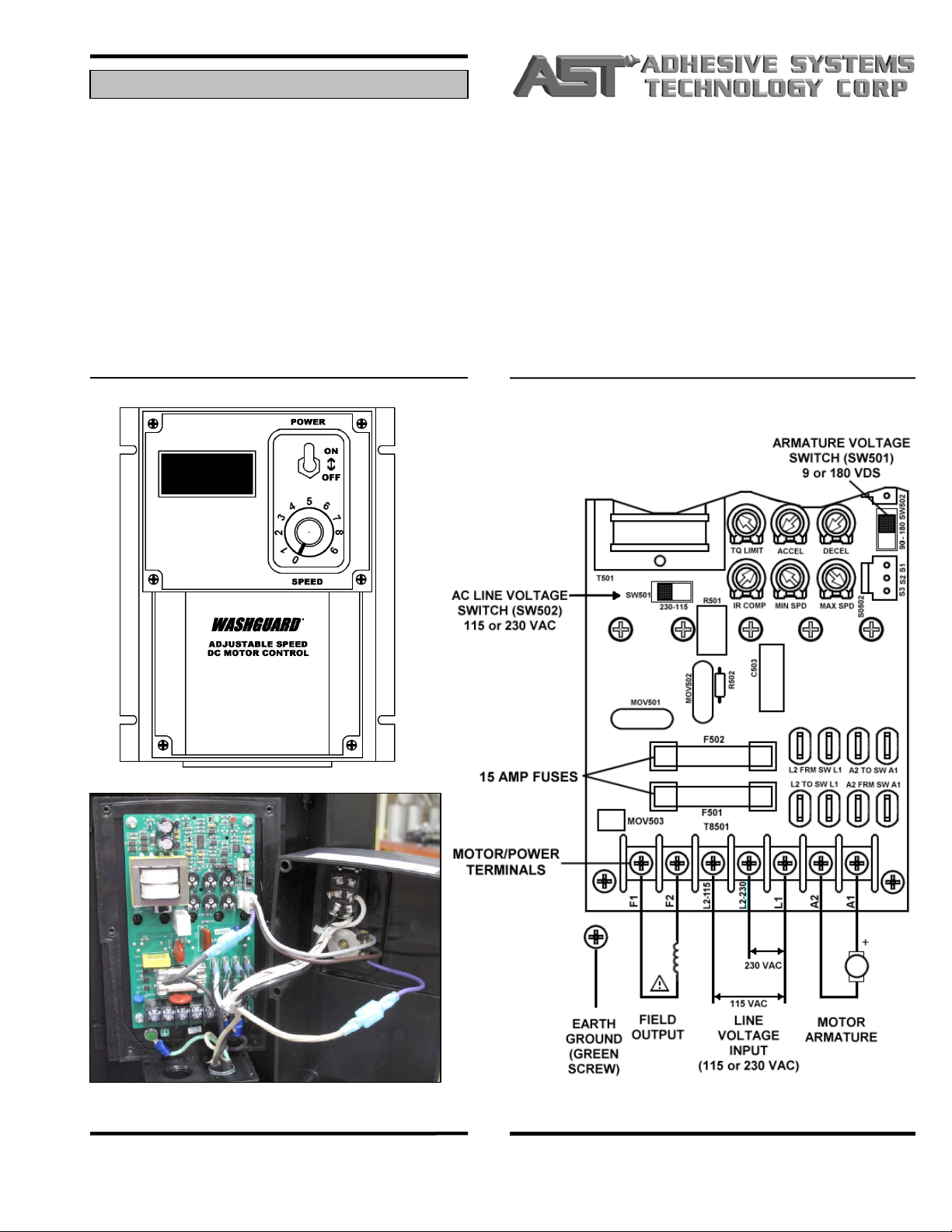
Connect motor controller to power supply (120VAC). Use a
ground fault interrupter (not supplied). Using a GFI Plug
will help protect the motor controller and greatly improve
service life.
If using an extension cord, it must be no longer than 100
feet, 14 gauge. Longer and/or smaller gauge supply may
starve the controller, causing erratic pump performance
and may cause the controller fuse to blow.
Do a preliminary check of system before filling material
containers. Actuate handle trigger & release signal to stop.
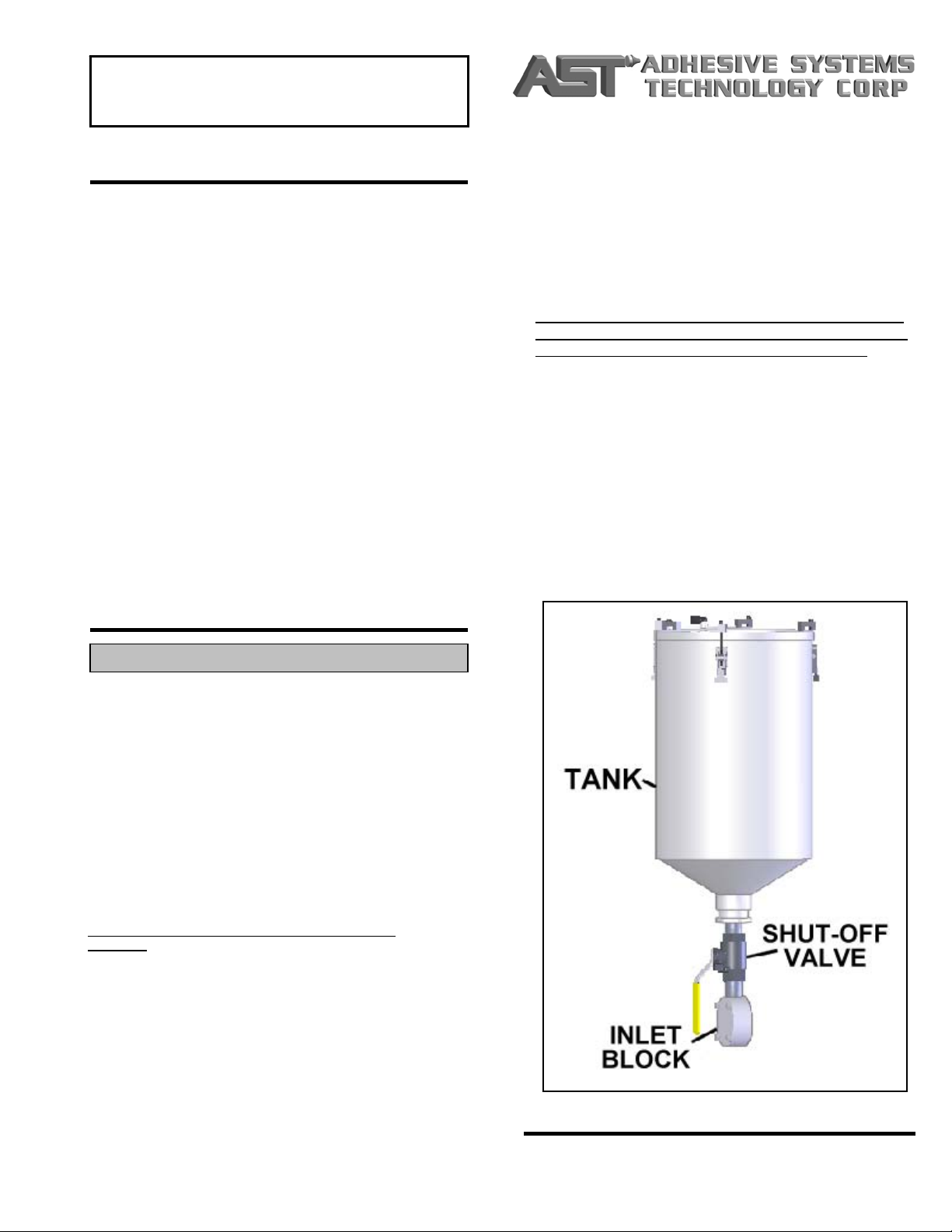
Filling containers with material: Make sure respective
materials are poured into designated containers. Fill at
least ½ full & place lid on each container immediately after
filling. Make sure inlet valves are open between pumps &
tanks. Label both containers to assure correct filling.
When filling, place lid on tank not being filled.
Filling hoses and applicator: Actuate system and slowly run
until allowing materials to flow through both hoses to the
applicator. IF MIXER NOZZLE HAS BEEN ATTACHED,
REMOVE TO AVOID MATERIAL CROSS-OVER.
HOSE FILLING PRECAUTION: Any high point in hose can
hold air and allow an air gap. Slope hose on a gradual
upward slope away from system to applicator while filling.
The dispense valve should also slope upward in a similar
manner until materials flow smoothly out of both ports of
the dispense manifold. In almost all cases, “A” and “B”
materials behave differently and fill at different rates. Let
earlier appearing material flow into waste container until
other material is also flowing freely.
Establish proper flow of both materials at dispense
manifold WITHOUT THE MIXER ATTACHED. Hold the
top into a waste container and actuate the system.
Observe flow of both materials from the round ports and
continue to run the system until a positive, air free flow is
achieved. Wipe clean
SET-UP & PRE-START CHECKS
TIPS
,
PRECAUTIONS & WARNINGS
Do not install a disposable mixer nozzle to the
dispense manifold until positive air-free flow is
achieved from both outlets of the applicator block tip.
The maximum cord length that can be used is 100 feet
using 14-gauge wire.

DAILY OPERATION
Open “A” and “B” container supply valves.
Check level of materials in containers, making sure level
is always over ¼ filled.
Clean off applicator dispense head with plastic mixer
nozzle removed
Verify smooth, air-free flow of both materials by
dispensing material into waste container. Check for two
smooth, consistent streams of material.
Wipe head clean and coat dispense head with
compatible lubricant.
Place new plastic mixer nozzle on dispense head with
retaining nut.
Dispense approximately 2 mixer volumes of material into
waste container.
Make 2 or 3 test samples to verify performance.
Remove static mixer nozzle.
Trigger applicator to relieve any pressure in lines or
system. Materials may ooze out of applicator.
Turn off or disconnect motor controller.
Fill dispense manifold with compatible lubricant. Fill
each zerk until material inside dispense manifold is
replaced with compatible lubricant.
Lubricate each pump:
oOpen bleed valve at bottom of pump.
oGrease zerk at top of pump until material coming out of
bleed port is clean, fresh lubricant.
oClose bleed valve & verify tanks are over 1/3 full.
Clean threads & ports of dispense manifold
Remove & soak manifold in compatible solvent, if
necessary
#60065-02: Page #7
VERY IMPORTANT: As soon as a problem is noticed,
immediately remove disposable mixer nozzle and try
dispensing material. This may prevent or purge material
crossover if it has not already hardened.
After static mixer is removed, THEN check the following:
Is the dispense manifold plugged? (Material set up)
Is there sufficient material in the tanks?
Is the pressure at the outlet gauges changed from
normal?
Is the machine dispensing on ratio?
If ratio is not correct:
Check if air is entrapped in the pumps or hoses
Check if the drive chain is loose or worn
Check if one or both of the pump sprockets are frozen
(Can the sprocket be rotate with a large pliers?)
START-UP
SHUT-DOWN
METERING PUMP MAINTENANCE
PERIODIC MAINTENANCE
DISPENSE VALVE MAINTENANCE
Remove retainer cap and/or mixer nozzle
Trigger applicator; two separate beads of material will
appear; compare for correct volume
Replace o-rings, packings & seals, if necessary
RATIO CHECK
TROUBLESHOOTING
Remove and clean any material residue or film with
compatible solvent (damp pad only – do not pour
solvent)
Lubricate with compatible lubricant.
If leakage appears at shaft, replace seals.
**Use caution when disassembling the Gerotor pump
making sure not to gouge or mar any of the internal
surfaces of the pump**

The following is the list of items to check if the equipment is not dispensing the correct ratio. Please note that some
items included in this procedure are not included with all supplied equipment. Please use all safety devices such as
but not limited to gloves and eye protection. When working with solvents do so in a well-ventilated area free of
combustible items. Take every effort not to mar or damage any surfaces that come in contact with materials.
If you suspect the ratio is incorrect and the dispense valve is in good condition, proceed as follows:
Remove retainer cap and/or mixer nozzle.
Trigger applicator; two separate beads of material will appear. Dispense each bead into separate cups; compare
for correct volume. If volume is correct with mixer off, metering pumps are worn & need to be replaced.
If volume is off, remove hoses from dispense valve and trigger applicator. Dispense each material into separate
cups. Compare volume of material dispensed out of material hoses. If volume is correct, the problem is occurring
in the dispense valve. Clean and/or replace seals, o-rings, & packings if necessary.
If ratio is still not correct, remove hoses at the outlet assembly. Trigger applicator and dispense each material into
separate cups. Compare volume of material dispensed out of outlet assembly. If volume is correct, the problem is
occurring in the material hoses. Clean and/or replace hoses.
If ratio is still not correct, disassembly and clean pumps. Replace seals & o-rings if necessary.
Other items of note:
Verify that the air inlet to the tank is in good condition. The air goes into the tank through the air dryer canister.
Check that the canister has holes in both ends and is not clogged with material. Next, check that the tubing from
the tank to the lid is not blocked. Also, check that the crystals inside the canister (through the little window on the
side) are light blue in color. Replace if pink in color.
Check for blockages on the inlet side of the pump with the reduced output. The round inlet block will have to be
taken off the back of the pump. Then, inspect the piping leading from the tank to the inlet block. If a blockage is
found, it may not be necessary to go any farther.
Clean and rebuild the pump. Check that the inner and outer gears are tight against each other. [Note: be careful
not to damage the inner pump parts when disassembling or cleaning. Replacement parts for the gerotors are
available only as a complete pump!] *Remove all crystallized or partially hardened material from all surfaces that
contact the material.
Check the outlet assembly (the piping between the pump and the hoses) for blockages.
#60065-02: Page #8
RATIO CHECK PROCEDURE
*NOTE: Any material that is left in the machine that is partially or completely hardened, or foreign objects, will
eventually cause a problem somewhere and should never be left in the pump.

Material not curing
#60065-02: Page #9
TROUBLESHOOTING GUIDE
Check Electrical Supply Verify that requirements are met (115/120v, 100’
extension
)
Unit Will Not Run
Check motor controller fuses Re
p
lace
Re
p
laceMotor / Gear box failure
Re
p
lace if unit runs when b
yp
assedSwitch in dis
p
ense assembl
y
handle
(ALWAYS remove power
when servicin
g)
Unit runs but no flow / low
flow of materials Im
p
ro
p
er material su
pp
l
y
to
p
um
p
sClear obstruction in tank bottom
Uno
p
ened or blocked air vent holes
Ti
g
hten / re
p
lace drive chain
Ti
g
hten / seal all material fittin
g
s
Desiccant caniste
r
Check chain drive
Air in material su
pp
l
y
Ratio check NOT okay
*Blockage of hoses
*Blockage in dispense assembly
*Blockage in pump
Clear / replace
Clear / replace
Replace
Rebuild
Plu
gg
ed hoses or dis
p
ense manifold
Worn Pum
p
s
Clear or re
p
lace
Verif
y
that material bein
g
used is non-abrasive
Too much flow Motor s
p
eed control Reduce settin
g
Check motor control s
p
eed settin
g
Ad
j
ust
p
er controller manual
Irregular flow Check valves stickin
g
/ blocked Disassemble & Clean
Remove tank & inlet; clea
r
Clear / re
p
lace
Re
p
lace
Blocka
g
e at
p
um
p
inlet
Blocka
g
e in hoses
Blocka
g
e in static mixer nozzle
Material off ratio
Timin
g
s
p
rockets wron
g
size
A or B
p
um
p
seals leakin
g
A or B check valves sticking (in dispense
assembl
y)
Static mixer worn or
p
lu
gg
ed
Static mixer does not have enough
elements for
p
ro
p
er mix
Lead in one material coming out of
dis
p
ense manifold
;
Air in material
Foreign object or cured material in pump or
p
um
p
inlet
1. Check material by hand: mix a sample of
A&B in the proper ratio
2
Doasystemratiocheck
Correct / re
p
lace
Rebuild Pum
p
Disassemble, clean, & rebuild; use new o-ring
Re
p
lace
Increase mixer size
Follow air bleed procedure
Remove tank & inlet, then clear or rebuild pump
Possible Causes/Areas to CheckProblem Remed
y

SHUT-DOWN PROCEDURES
The following is the recommended procedure for removing,
inspecting, cleaning and reinstalling GMP pumps. Please use
all safety devices such as but not limited to gloves and eye
protection. When working with solvents do so in a well-
ventilated area free of combustible items. Take every effort not
to mar or damage any surfaces that come in contact with
materials.
Disassembly
oRemove tank & inlet [assuming all material has been
removed from tanks].
Open bleed valve on top of inlet block, if supplied.
Remove tank straps, if supplied.
Remove (3) of the 4 bolts attaching inlet to back of
pump
Loosen fourth bolt to allow inlet to come off pump and
drain any remaining material. Remove bolt and tank
after enough material is drained.
Discard o-ring between inlet & pump (12498).
Clear any foreign objects, crystallized or partially
hardened material from tank & inlet block.
Cleaning of residues from pump
oPartially disassemble & clean pump
Remove four bolts attaching inlet to back of pump.
Back of pump should pull off shaft & front section.
Excessive force should be used only with extreme
caution to prevent damage to the pump (Be careful to
not lose the two alignment pins, which prevent incorrect
assembly of pump. Clean pins if necessary).
Clean bolts of any material.
Prevent any damage to all interior surfaces of pump.
Carefully remove outer stator ring housing. Assuming
that any crystallized material is located between stator
(internal teeth) and rotor (external teeth), soak area in
contact with material in a compatible solvent to soften.
Gently remove & clean stator. Rotor should be carefully
cleaned at this time while still mounted on pump shaft.
Use nylon brushes instead of steel if possible to
preserve surface finished.
Keep all parts, except for o-rings.
All residues of old material are to be removed from all
internal surfaces of the pump parts.
Test to see if pump shaft can be turned.
Check to see if motor will turn by turning on the
machine briefly.
Remove chain and turn sprocket. Use a wrench, if
necessary.
If pump shaft will turn, further disassembly is
unnecessary unless material is leaking from shaft
seals (check behind drive sprocket).
Once completely clean, re-assemble pumps. *Note:
Mechanical side of pumps cannot be assembled
incorrectly if the two (2) guide pins are in place. Use
new o-rings. The use of petrolatum grease is
#60065-02: Page #10
PUMP CLEANING PROCEDURE recommended to lubricate all internal surfaces
immediately before installation and may make re-
assembly easier along with future servicing of pump.
Lubricate pumps using zerks supplied. Use only
petrolatum grease for this purpose.
Load Material into machine per operator’s manual.
Test machine per operator’s manual.
oCheck cured material for uniform cure and consistency.
oSee “Troubleshooting” section in operator’s manual if any
problems are observed.
Restock any items used in procedure.
The following is the recommended procedure for storing
equipment for a shot period of time. Please note that some
items included in this procedure are not included with all
supplied equipment. Please use all safety devices such as but
not limited to gloves and eye protection. When working with
solvents do so in a well-ventilated area free of combustible
items. Take every effort not to mar or damage any surfaces
that come in contact with materials.
Pump Unit Dry
oPump remaining material.
Remove static mixer and/or spray attachment.
Operate machine until no material is being dispensed.
Check that hoses are allowed to drain completely
(hoses should lead “downhill” towards dispense valve).
Clean dispense valve & reapply layer of compatible
lubricant.
oFlush System
Use only a cleaning solution most effective for removing
your material. Consult manufacturer for
recommendations. Carefully observe all health and
safety precautions listed on all labeling.
Fill each tank a minimum of 1/3 with a compatible
cleaning solution.
Set pump speed control to slow setting.
Operate machine until cleaning solution begins to come
out of the machine.
Allow machine to sit for a period of time, depending on
the effectiveness of the cleaning solution, not more than
one hour. Most solvents will not damage any
component unless allowed to remain in system.
Continue pumping cleaning solution into container until
machine is again empty. Observe cleaner as it is being
pumped. As solution is pumped, it should appear to
become clean. If this is not observed, the same
cleaner, after impurities have settled, can be re-loaded
into machine and procedure repeated – if it is pumped
out immediately. Do not allow any settled material back
into s
y
stem.
SHORT-TERM SHUTDOWN PROCEDURE
(CONTINUED ON PAGE #11)

oTank/Material Feed System
Clean & inspect tank lid sealing gaskets. Repair with
RTV Silicone as necessary.
Check desiccant canister. Verify that crystals are blue
in color through window in side of canister. Replace if
crystals are not blue.
Check makeup air lines from desiccant canister to tank.
Remove or repair any blockages.
Clean inside of tanks, concentrating on any material
built up that might wind up in pumps.
Start-up Procedure
oPrepare system for loading
Pre-season startup checks outlined below should be
performed in advance of any intended use.
AST assumes previous shut-down procedure was
followed.
Connect electrical power.
Open ball valves under tanks
Test operation of machine. Verify that oil loaded into
machine comes out both ports on the dispense valve
when triggered.
Operate system until empty.
oFlush system with compatible solvent
Fill each tank a minimum of 1/3 full with a compatible
cleaning solution.
Operate and observe behavior of system.
*NOTE: Gauges will not read normal pressures while
pumping solvent due to the fact that solvents are less
viscous, therefore requiring less pressure to pump.
Verify that flow is coming out of both ports in dispense
valve.
Operate system until empty. Please not that it is not
harmful to run machine dry.
If available, open ball valve under pump inlet block to
verify that all solvent is drained from tanks.
If possible, temporarily disconnect material hoses from
dispense valve and allow any trapped solvent to drain.
Fill zerks on dispense valve with petrolatum grease until
lubricant coming out of ports is clean.
oLoad & Test Material
Load each material into correct tank. Remember to
keep one lid on while filling the other tank.
Verify that ball valves above each pump and at outlet
assembly are open.
Set motor speed to low (30%) and actuate trigger,
operating system until correct material comes out both
ports of dispense valve.
Observe pressure gauges while filling system. A spike
in pressure would indicate a blockage downstream from
pump.
Operate system until two streams of material come out
of dispense valve. Release trigger and wipe manifold.
#60065-02: Page #11
Attach static mixer to dispense valve. Make several test
shots of material in small cups or on aluminum foil and
allow curing.
Discard static mixer, wipe manifold clean, and re-fill
manifold with petrolatum grease.
Check cured material for flaws and inconsistencies.
See “Troubleshooting” section in operator’s manual if
any problems are observed.
The following is the recommended procedure for storing
equipment for an extended period of time. Please note that
some items included in this procedure are not included with all
supplied equipment. Please use all safety devices such as but
not limited to gloves and eye protection. When working with
solvents do so in a well-ventilated area free of combustible
items. Take every effort not to mar or damage any surfaces
that come in contact with materials.
Pump Unit Dry
oPump remaining material.
Remove static mixer and/or spray attachment.
Operate machine until no material is being dispensed.
Check that hoses are allowed to drain completely
(hoses should lead “downhill” towards dispense valve).
Clean dispense valve & reapply layer of petrolatum
grease.
oFlush System
Use only a cleaning solution most effective for removing
your material. Consult material manufacturer for
recommendations. Carefully observe all health and
safety precautions listed on all labeling.
Fill each tank a minimum of 1/3 with a compatible
cleaning solution.
Set pump speed control to slow setting.
Operate machine until cleaning solution begins coming
out of machine.
Allow machine to sit for a period of time, depending on
effectiveness of cleaning solution, not more than one
hour. Most solvents will not damage any component
unless allowed to remain in system.
Continue pumping cleaning solution into container until
machine is again empty. Observe cleaner as it is being
pumped. As solution is pumped, it should appear to
become clean. If this is not observed, the same
cleaner, after impurities have settled, can be reloaded
into machine and procedure repeated – if it is pumped
out immediately. Do not allow any settled material back
into system.
oTank/Material Feed System
Clean & inspect tank lid sealing gaskets. Repair with
RTV Silicone as necessary.
END OF SEASON SHUTDOWN PROCEDURE
(CONTINUED ON PAGE #12)
(CONTINUED FROM PAGE #10)

Check desiccant canister. Verify that crystals are blue
in color through window in side of canister. Replace if
crystals are not blue.
Check makeup of air lines from desiccant canister to
tank. Remove or repair any blockages.
Clean inside of tanks, concentrating on any material
built up that might wind up in pumps.
oRe-fill System for Storage
Fill tanks with compatible oil/lubricant and trigger.
Close ball valves.
Start-up Procedure
oPrepare system for loading
Pre-season startup checks outlined below should be
performed in advance of any intended use.
AST assumes previous shut-down procedure was
followed.
Connect air supply & electrical power.
Open ball valves under tanks
Test operation of machine. Verify that oil loaded into
machine comes out both ports on the dispense valve
when triggered.
Operate system until empty.
oFlush system with compatible solvent
Fill each tank a minimum of 1/3 with a compatible
cleaning solution.
Operate and observe behavior of system.
*NOTE: Gauges will not read normal pressures while
pumping solvent due to the fact that solvents are less
viscous, therefore requiring less pressure to pump.
#60065-02: Page #12
Verify that flow is observed coming out of both ports in
dispense valve.
Operate system until empty. Please note that it is not
harmful to pump machine dry.
If available, open ball valve under pump inlet block to
verify that all solvent is drained from tanks.
If possible, temporarily disconnect material hoses from
dispense manifold and allow any trapped solvent to
drain.
Fill zerks on dispense valve with petrolatum grease until
lubricant coming out of ports is clean.
oLoad & Test Material
Load each material into correct tank. Remember to
keep one lid on while filling the other tank.
Verify that ball valves above each pump and at outlet
assembly are open.
Set motor speed to low (30%) and actuate trigger,
operating system until correct material comes out both
ports of dispense valve.
Observe pressure gauges while filling system. A spike
in pressure would indicate a blockage downstream from
pump.
Operate system until two streams of material come out
of dispense valve. Release trigger and wipe manifold.
Attach static mixer to dispense valve. Make several test
shots of material in small cups or on aluminum foil and
allow material to cure.
Discard static mixer; wipe manifold clean, and re-fill
manifold with petrolatum grease.
Check cured material for flaws and inconsistencies.
See “Troubleshooting” section in operator’s manual if
any problems are observed.
(CONTINUED FROM PAGE #11)

QtyPart # Description
1 26284D 1 FRAME WELDMENT, GMP-025, 2017, WELDED HANDLES AND AXLES, SHIPPING HOLES
2 55914-06 1 ASSEMBLY, HOLSTER, PCH EXTENSION, PNEUMATIC PANEL MOUNTED, 1/2 SPACERS
3 11123 2 GRIP, HANDLE, RIBBED W/ FINGER GROOVES, 1 ID X 4-9/16 LONG
4 55625-01C 1 SCHEMATIC, ELECTRICAL, MANUAL PCH GMP-025/050
5 25392-03A 1 SHROUD, PUMP DRIVE, GMP025, 2017
6 55916-02J 1 DRIVE ASSEMBLY, MAINFRAME, PCH GMP-025
7 55617A 2 OUTLET ASSEMBLY, PUMP, GMP, 3/8, VERTICAL GAUGE, No. 6
8 55913-16 2 INLET ASSEMBLY, GMP, 6 GALLON TANK W/ SCREEN
9 33340 12 HOSE, CORRUGATED, 1-1/4 I.D., POLYETHYLENE, PER FOOT
10 11299-15 2 HOSE, TEFLON, 3/8 ID x 15’, 6 JIC SWIVEL ENDS
11 55918-03A 1 ASSEMBLY, WHEEL/HARDWARE, GMP-025, W/ WELDED AXLES
12 55615-01D 1 DISPENSE, EXTENSION ASSEMBLY, VALVE W/ BALL VALVES, INTERNAL CHECK, GMP-025/050
13 55472A 1 DRYER ASSEMBLY, DESICCANT CARTRIDGE WITH BRACKET
14 14707 1 LABEL/ DECAL, B & W “AST 1-3/8 X 4-3/8 X 3.5 MILS, VINYL W/ POLYESTER OVERLAY
15 11447 2 RIVET, POP, 1/8 DIAMETER x 1/16-1/8 GRIP RANGE
16 11124 2 DECAL, LETTER, A, 3, BLACK
17 11125 2 DECAL, LETTER, B, 3, BLACK
18 11943 6 BOLT, 10-24 x 1/2, SHCS
19 12627B 1 TAG, SERIAL NUMBER, ALUMINUM
AST PUMP SYSTEM, PCH GMP025-1616, 6 GALLON SS TANKS, AST INVENTORY
PRODUCT NAME:
D.J.S.
ENGINEER
90069-01D
PRODUCT #
3/22/2018
ORIG DATE
19
# OF ITEMS
Item

AST

Created: By: Modified: By:
9/11/03 9/11/03 Anthon
y
WalshAnthon
y
Walsh
QtyPart No. Description
AST Bill of Materials
ASSEMBLY,HOLSTER,PCHEXTENSION,PNEUMATICPANELMOUNTED,1/2SPACERS
PRODUCT NAME
Engineer
55914-06
PRODUCT #
Orig Date 5
# Of Items
Item
1 23912-01 1 HOLSTER, WELDMENT, PCH EXTENSION ASSEMBLY, 55615 / 55474
2 22937-04 2 SPACER, 1” OD x 17/32” ID x 1/2” L, ALUMINUM
3 11759 2 BOLT, 5/16"-18 x 3", HEX, GR5
4 11052 4 WASHER, 5/16" SAE FLAT, STEEL
5 11053 2 NUT, 5/16"-18, HEX, NYLOCK


QtyPart # Description
1 14644A 1 CONTROLLER, MOTOR, NEMA 4, 1 HP, 90/ 180 VDC- See 56422-XXA
2 14702 1 CORD, POWER, 3 PRONG, MOLDED PLUG, 120 V, 6FT LONG
3 12862-02 2 GROMMET, PLASTIC, 7/8 OD x 5/8 ID
4 12863-06 1 GRIP, CORD, 3/8 ID, 1/2 NPT
5 12863-10 1 GRIP, CORD, 5/8 ID, 1/2 NPT
6 13012 1 TERMINAL, SLIDE, MALE, 16-14 GA CONNECTOR
7 13013 1 TERMINAL, SLIDE, FEMALE, 16-14 GA CONNECTOR (1/4 SPADE CONNECTOR)
8 13016 5 TERMINAL, SPADE, 16-14 GA, #6 STUD, 100 PIECE PACK
SCHEMATIC, ELECTRICAL, GMP-SP-025, 14644A MOTOR CONTROLLER
PRODUCT NAME:
ENGINEER
55625-01C
PRODUCT #
ORIG DATE
8
# OF ITEMS
Item

2
3
331
005. MORFECNATSID.PYT OTSYELLUPFOKCAB ETA
LPEMARFNIAM
5
8
9
11
21
01
41518171
91
1
4
4
4
67
KCK 61/60
J
20-61955
B
LAITNEDIFNOCDNAYRATEIRPORP
.M.O.BEES
SEHCNINIERASNOISNEMID :SECNARELOT HCAM:RALUGNADNEB1
XXXX500.
XXX010.
XX510.
NWARD
DEK
CEHC
.RPPAGNE
.RPPAGFM
.A.Q
ETAD
EMAN
D
C
B
A
A
B
C
D
1
2
3
4
5
6
78
87654321
hsiniF
:ELTIT
EZIS .ON.GWD VER
8:1:ELACS1FO1TEEHS
SIHTNIDENIATNOCNOITAMROFNIEHT FOYTREPORPEL
OSEHTSIGNIWARD NINOITCUDORPERYNA.PROCTSA EHTTU
OHTIWELOHWASAROTRAP SI.PROCTSAFONOISSIMREPNETTIRW .DETIBIHORP
CIRTEMOEGTERPRETNI :REPGNICNAR
ELOT
LAIRETAM
HSINIF
YSSATXEN NODESU
NOITACILPPA ELACSTONOD GNIWARD
,YLBMESSAEVIRD 520-PMG,EMARFNIAM
:DEIFICEPSESIWREHTOSSELNU
:SETON .SDRADNATS.GFMTSAREPELBMESSA.1
SNOISIVER
.VERNOITPIRCSEDETAD
This manual suits for next models
1
Table of contents
Other AST Paint Sprayer manuals
Popular Paint Sprayer manuals by other brands

VOS
VOS 6313-FS1751 quick start guide

Graco
Graco DURON Performance 395 A Series Instructions-parts list

Solo
Solo 425-101 Operator's manual & parts list

National Garden Wholesale
National Garden Wholesale EZ Sprayer user manual

Graco
Graco Xtreme NXT Brochure & specs

Solo
Solo 425 Classic Operator's manual & parts list

Krautzberger
Krautzberger MA-1 operating instructions

Binks
Binks 44-6000 Operation and maintenance instructions

Birchmeier
Birchmeier REB 15 AC1 Instructions for use

Graco
Graco GX-8 Operation, parts, service, repair

Sagola
Sagola PSAA 108 Instruction manual and spare parts list

Fimco
Fimco SK-61-12V-TSC Assembly / operation instructions / parts