Agri-Fab Lawn Care Made Easy HIM-1222 User manual

FORM NO. 3-217 (03/07/23)
the fastest way to purchase parts
www.speedepart.com
45-0603
ZERO TURN SPRAYER
youtube.com/c/agrifab
Video
Instruction
Guide
Want more information or assembly tips?
................................................................3,4
ENGLISH............................................................5
FRANÇAIS .......................................................12
ESPAÑOL.........................................................17

2
SAFETY RULES
Remember, any equipment can cause injury if operated improperly or if the user does not understand how to operate the
equipment. Exercise caution at all times when using this equipment.
LOOK FOR THIS SYMBOL TO POINT OUT
IMPORTANT SAFETY PRECAUTIONS. IT
MEANS - ATTENTION! BECOME ALERT!
YOUR SAFETY IS INVOLVED.
CAUTION: VEHICLE BRAKING AND
STABILITY MAY BE AFFECTED WITH
THE ADDITION OF AN ACCESSORY
OR AN ATTACHMENT. BE AWARE OF
CHANGING CONDITIONS ON SLOPES.
Exercise caution at all times when using power equipment.
1. Read this owners manual carefully for operating and service instructions before attempting to assemble or operate this
equipment. Be thoroughly familiar with the proper use of this equipment.
2. Read the vehicle owners manual and vehicle safety rules, and know how to operate the vehicle before using this
equipment.
3. Never allow children to operate the tractor or sprayer, and do not allow adults to operate without proper instructions.
4. Do not allow anyone to ride on or sit on this sprayer.
5. Keep the area of operation clear of all persons, particularly small children, and also pets.
6. Read the chemical label before handling or mixing chemicals.
7. Wear eye and hand protection and protective clothing when handling and applying lawn chemicals.
8. Do not spray on windy days.
9. Always begin with the transmission in rst (low) gear and engine at low speed, and gradually increase speed as
conditions permit.
10. The vehicle braking and stability may be affected with the attachment of this equipment. Be aware of changing
conditions on slopes. Refer to safety rules in the vehicle owner's manual concerning safe operation on slopes. STAY
OFF OF STEEP SLOPES.
11. Always operate up and down a slope, never across the face of a slope
12. This equipment should be operated at reduced speed on rough terrain, along creeks and ditches and on hillsides, to
prevent tipping and loss of control. Do not drive too close to a creek or a ditch.
13. Do not tow this equipment on a highway or any other public thoroughfare.
14. Follow the maintenance instructions as outlined in this owners manual.

3
CARTON CONTENTS - PARTS
1
3
2
4
5
11
6
8
9
10
13
12
7
REF QTY PART NO DESCRIPTION
1 1 6-926 Boom Assembly ZT
2 1 2-541BL3 Bracket, Boom Support
3 1 6-1030 15 Gallon Tank Assembly
4 2 2-741 Boom Support Rod
5 2 45908BL3 Mounting Bracket
6 2 45909 U-Bolt, 7.0 X 3.5 X 3/8"
7 2 45814BL3 Slider Tube
REF QTY PART NO DESCRIPTION
8 1 69643BL3 Hitch Mount Ass'y
9 1 2-542BL3 Tube, Receiver Hitch
10 1 2-540BL3 Tube, Frame
11 1 2-539BL3 Tube, Frame Rear 1 X 2
12 1 ST43472 Wire Harness, Switch
13 1 ST43483 Wire Harness, Battery

4
CARTON CONTENTS - HARDWARE
REF QTY PART NO DESCRIPTION
A 1 43351 Bolt, Hex 1/2-13 X 1-1/4 GR5
B 4 43084 Bolt, Hex 5/16-18 X 1-3/4 GR5
C 2 43432 Bolt, Hex 3/8-16 X 2-1/2 GR5
D 3 46071 Bolt, Hex 1/4-20 X 3-1/4 GR5
E 4 43015 Nut, Hex 3/8-16
F 3 47189 Nut, Hex 1/4-20 Nylock
G 1 41657 Nut, Hex 1/2-13 Nylock
H 2 HA21362 Nut, Hex 3/8-16 Nylock
REF QTY PART NO DESCRIPTION
I 8 44072 Nut, Hex 3/8-16 Whizloc
J 4 43003 Washer, Loc 3/8"
K 2 1540-118 Washer, .531 X 1.25 X .062
L 4 43081 Washer, .735 X .875 X .083
M 4 28325 Spacer, .31 ID X .585 OD X 41
N 1 HA23636 Pin, Clevis 3/8" X 2-1/4"
O 1 43343 Pin, Hair Cotter 3/32" X 2-5/16"
P 2 ST43314 Plastic Wire Harness Clips
A B C D
E
J K L M N
O
F G H I
P
NOT SHOWN FULL SIZE
x1
x4 x2 x4 x4 x1
x1
x4 x2 x3
x4 x3 x1 x2 x4
43351
43003
43432 46071
43081
43015
28325
47189
HA23636
41657
43343
HA21362 4407243084
1540-118
x2
ST43314

5
TOOLS REQUIRED FOR ASSEMBLY
(2) Adjustable Wrench
(2) 7/16" Wrenches
(2) 1/2" Wrenches
(2) 9/16" Wrenches
Lay out and identify the parts and hardware using the
illustrations on page 3 and page 4.
ASSEMBLE THE HITCH MOUNT ASSEMBLY
STEP 1: (SEE FIGURE 1)
• Insert a slider tube (7) into each end of the hitch
mount assembly (8).
• Attach the slider tube to the hitch mount assembly
using two hex bolts (C), four washers (L), and two
Nylock hex nuts (H). Do not tighten.
7
7
8
H
L
C
L
FIGURE 1
STEP 2: (SEE FIGURE 2)
• Attach the hitch mount assembly (8) to the tractor
frame using two U-bolts (6) secured with two mounting
brackets (5), four washers (J), and four hex nuts(E).
Do not tighten.
• If the slider tube does not fully extend into both
U-bolts(6), then loosen the appropriate hex bolt (C)
and reposition the slider tube (7).
• Center the hitch mount assembly on the tractor frame.
• Tighten all hex bolts and hex nuts.
7
8
6
5
J
E
C
FIGURE 2
ASSEMBLY INSTRUCTIONS
Note: Depending on your mower, U-bolts may need to be
installed at an angle.

6
ASSEMBLE THE TUBE FRAME ASSEMBLY
STEP 3: (SEE FIGURE 3)
• Attach the tube frame (10) to the receiver hitch
frame(9) using a hex bolt (D) and a Nylock hex
nut(F). Do not tighten yet.
• Attach the rear tube frame (11) to the receiver hitch
frame (9) using two hex bolts (D) and two Nylock hex
nuts (F). Do not tighten yet.
D
D
11
10
9
F
FIGURE 3
ATTACH TUBE FRAME ASSEMBLY TO THE
TANK
STEP 4: (SEE FIGURE 4)
M
3
B
FIGURE 4
ATTACH THE TANK ASSEMBLY TO THE
HITCH MOUNT ASSEMBLY
STEP 5: (SEE FIGURE 5)
• Attach the tank assembly to the hitch mount assembly
using one clevis pin (N) and one hair cotter pin (O).
N
O
FIGURE 5
ATTACH THE BOOM ASSEMBLY TO THE
BOOM SUPPORT BRACKET
STEP 6: (SEE FIGURE 6)
• Attach the boom support rods (4) to the boom
assembly (1) using four hex nuts (I).
• Attach the boom support rods (4) to the boom support
bracket (2) using four hex nuts (I).
I
I
I
I
2
1
4
FIGURE 6
Note: Do not overtighten the hex bolts
• Attach the tube frame assembly to the 15
gallon tankassembly (3) using four hex bolts
(B) and four spacers (M).
• Now tighten tube frame bolts from Step 3.

7
ATTACH THE BOOM SUPPORT BRACKET TO
THE TRACTOR HITCH
STEP 7: (SEE FIGURE 7)
• Attach the boom support bracket (2) to the tractor hitch
using one hex bolt (A), two washers (K), and one hex
nut (G).
A
K
K
G
FIGURE 7
CONNECT TANK HOSE TO THE BOOM
ASSEMBLY
STEP 8: (SEE FIGURE 8)
• Attach the tank hose to the 3/8" tee barb on the boom
assembly .
FIGURE 8
ATTACH WIRE HARNESS TO THE BATTERY
STEP 9: (SEE FIGURE 8)
• Attach ring terminals to the correct battery terminals
(Note: Red to Red and Black to Black).
• Connect the wire harness switch (12) to the wire
harness battery (13).
• Route the wire harness switch towards the sprayer
using the plastic wire harness clips (P). Note: Be sure
to secure the harness clear of exhaust, fans, and pinch
points.
• Attach the wire harness switch (12) to pump harness.
13 12
FIGURE 9
Note: May require hitch kit 45-0596

8
OPERATION
CAUTION: Connect to a 12 V battery only.
PUMP PRESSURE SWITCH
The pump pressure switch turns off the pump when it
reaches its maximum pressure setting. Very low ow
demand may cause the switch to rapidly cycle the pump
on and off. Rapid on and off cycling must be limited to
no more than 6 times per minute. Cycling could cause
the motor to heat beyond the recommended maximum
temperature and reduce the operational life of the pump
and pressure switch.
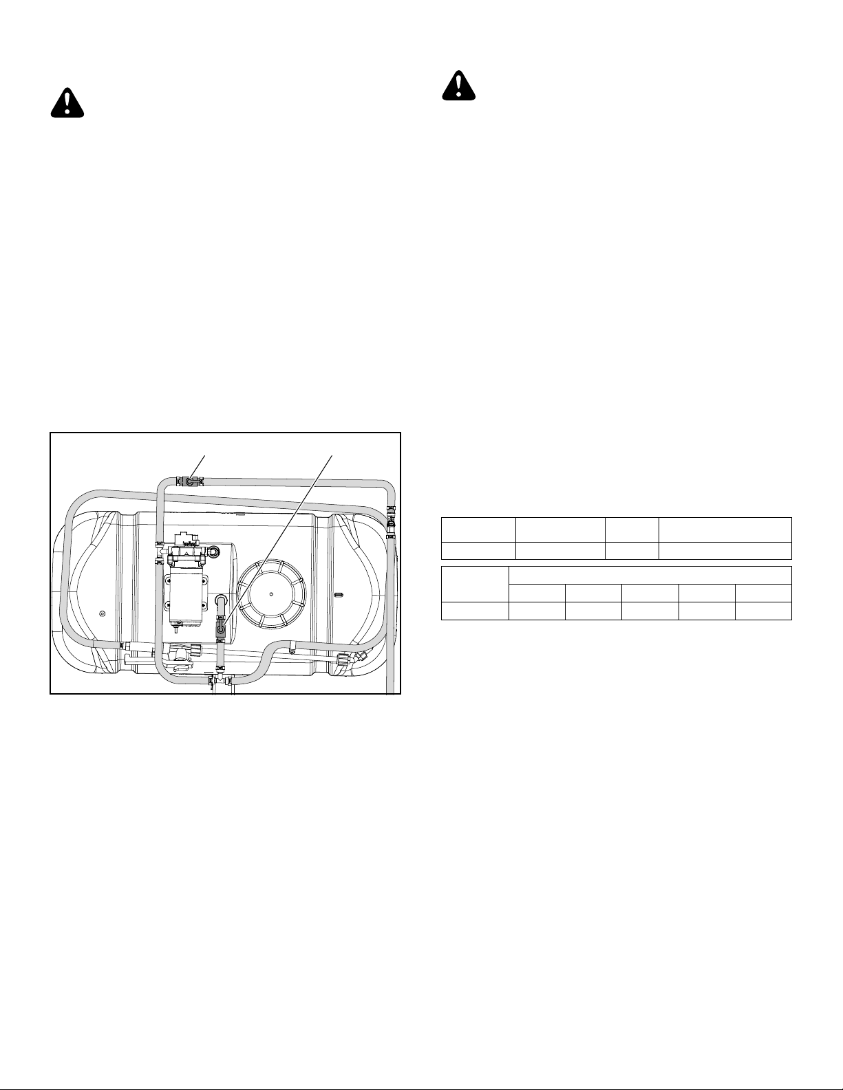
SPRAYER CONTROLS
Boom ON-OFF valve shuts off the ow to the boom
nozzles.
Recirculation valve adjust spray wand pressure and
recirculation of spray material to the tank.
Boom Valve Recirculation Valve
FIGURE 10
ADJUSTABLE SPRAY GUN NOZZLE
Twisting the nozzle will adjust the spray pattern from a
cone shaped mist to a solid stream.
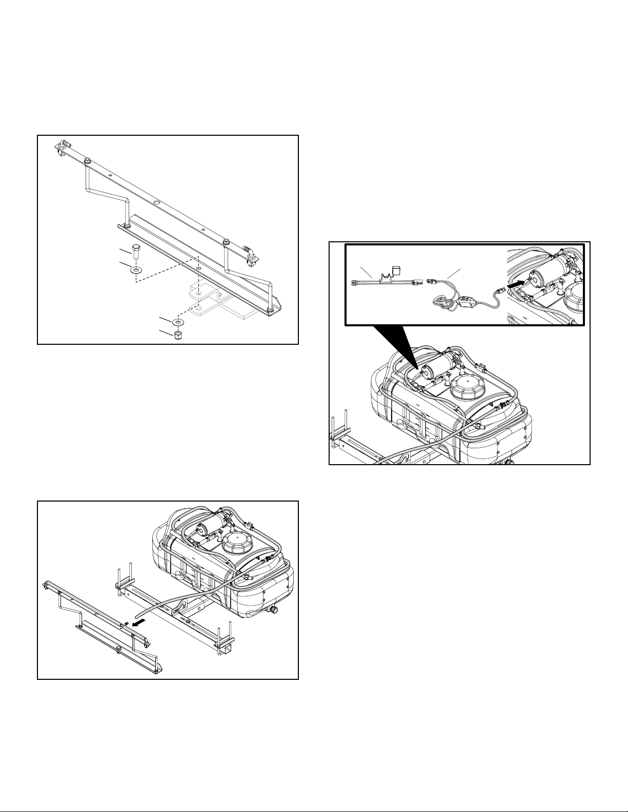
BEFORE STARTING
1. Attach the sprayer to the tractor hitch.
2. Connect the wire harness from the switch to the
pump.
3. Check for leaks using plain water. Fix leaking ttings
with thread tape.
USING THE SPRAYER
CAUTION: Wear eye and hand protection and
protective clothing when handling and working with
lawn chemicals.
1. Determine the application rate (gallons per 1,000sq.
feet) based on the chemical manufacturers
recommendations.
2. Estimate the size of the area to be sprayed and the
amount of solution that will be needed. This can help
avoid unneeded solution left in the tank.
3. Refer to the application chart below to help determine
the speed required to achieve the manufacturers
recommended application rate.
4. Check spray tips. Tips should be aligned with boom
as shown. If necessary, loosen spray tip cap nut. Align
spray tip and tighten cap nut.
5. Test spray pattern with water on driveway or sidewalk.
Each spray tip pattern should spread out to the right
and left sides, rather than to the front and back of the
boom. There should be some spray overlap between
each tip and the spray patterns should be consistent.
6. Add the chemical solution to the tank, following the
manufacturers recommendations.
APPLICATION CHART
Sprayer Tip Size PSI GMP One Nozzle
15 Gallon TP11008VP 35 0.75
Sprayer Gallons per 1000 Sq. Ft.
2 mph 3 mph 4 mph 5 mph 6 mph
15 Gallon 74.3 50 37.2 29.7 24.75

9
USING THE SPRAY GUN
1. Shut off the boom by turning the boom valve to
"OFF".
SPRAYER RECIRCULATION
1. The sprayer is equipped with a recirculation valve to
aid in material agitation and pressure control.
2. This valve is in the “open” position when the valve
handle is in line with the hose (pictured), “closed”
when perpendicular to the hose.
3. Adjusting the recirculation valve between the open/
closed positions will affect the pressure coming
through the spray wand only.
4. Closed position is full pressure through spray wand or
boom.
5. It may be helpful to adjust the pressure when
spraying with the spray wand to avoid damage to
plants from excess pressure.
6. This valve should be in the “closed” position when
operating the boom.
MAINTENANCE
AFTER EACH USE
1. Fill the sprayer part way with water and pump the
water out through the boom assembly and the
handgun. Use the handgun to wash the inside of the
tank.
2. Rell the tank about half full with water and a
chemical neutralizer solution and repeat the cleaning
instructions above. Follow the manufacturers
instructions for disposal of all chemicals.
AS NEEDED
1. Periodically clean the tank strainer on the end of the
intake hose. Remove the nylon swivel nut from the
hose, pull out the screen and ush it with water.
2. Periodically clean the strainers in the boom nozzles.
Remove the nozzle, pull out the screen and ush it
with water.
WINTER STORAGE
1. Drain all water out of the sprayer, especially the pump
and handgun. These items are prone to damage from
freezing temperatures.
2. Winterize the sprayer by pumping a 50-50 solution
of water and R.V. antifreeze through the boom
assembly and the hand gun.

10
REPAIR PARTS FOR 45-0603 ZERO TURN SPRAYER
44
49
6
42
45
43
46
47
9
32
11
12
11
29
8
41
50
48
26
33
11
22 21
11 16
11
11
30
28
11
11
12 11
29
32
29
5
9
6
6
59
58
39
55
57
40
53
11
10
44
11
34
36
4
23
51
24
13
14
52
60
61
4
18
35
1
1
17
20 37
19
7
7
38
56
55
3
2
25
15 11
31
54
62

11
REPAIR PARTS FOR 45-0603 ZERO TURN SPRAYER
REF QTY PART NO DESCRIPTION
1 2 46677 Screw, 10-24 X 3/8 PL
2 4 ST65001 Screw, 10-24 X 1" Truss Head
3 4 43084 Bolt, Hex 5/16-18 X 1-3/4 GR5
4 3 46071 Bolt, Hex 1/4-20 X 3-1/4
5 1 43351 Bolt, Hex 1/2-13 X 1-1/4 GR5
6 8 44072 Nut, Hex 3/8-16 Whizlock
7 3 47189 Nut, Hex 1/4-20 Nylock
8 1 41657 Nut, Hex 1/2-13 Nylock
9 2 1540-118 Washer, .531 X 1.25 X .062
10 1 ST43655 Oetiker Clamp 3/8" 0165
11 12 ST43010 Oetiker Clamp 3/8" 0185
12 2 ST43014 In Line Valve 3/8" Barb
13 1 ST43182 Sump Fitting 3/8" Barb
14 1 ST43258 Sump Strainer 3/8"
15 1 ST43183 Elbow 3/8" Mp - 3/8" Barb
16 1 ST43235 Tee 3/8" Barb - 3/8" Barb - 3
17 1 ST43287 Spray Wand Holder, Large
18 4 28325 Spacer, .31 ID X .585 OD X 41
19 1 HA23636 Pin, Clevis 3/8 X 2-1/4
20 1 43343 Pin, Hair Cotter 3/32 X 2-5/1
21 1 2-684 Hose Disconnect Coupling Body
22 1 2-685 Hose Disconnect Coupling Insert
23 1 ST43191 Hose Holder 3/8"
24 1 2-465 15 Gallon Tank, Drilled
25 1 ST43918 Pump 12V, 100 PSI, 2.2 GPM
26 1 ST43175 Tank Fill Cap
27 1 ST44017 Tank Fill Cap Lanyard (Not Shown)
28 1 2-342 Hose, 3/8" X 3.25"
29 2 2-319 Hose, 3/8" X 8.5"
30 1 2-318 Hose, 3/8" X 12"
31 1 2-337 Hose, 3/8" X 14.75"
32 2 2-314 Hose, 3/8" X 22"
33 1 2-807 Hose, 3/8" X 132"
REF QTY PART NO DESCRIPTION
34 1 2-345 Hose, 3/8" X 228"
35 1 2-539BL3 Tube, Frame Rear 1 X 2
36 1 2-540BL3 Tube, Frame
37 1 2-542BL3 Tube, Receiver Hitch
38 2 45814BL3 Slider Tube
39 2 45908BL3 Mounting Bracket
40 2 45909 U-Bolt, 7.0 X 3.5 X 3/8"
41 1 69643BL3 Hitch Mount Ass'y
42 2 ST43011 Elbow 3/8" Barb Tip Fitting
43 2 ST43012 Tip Fitting Cap Nut
44 2 ST43013 Tee 3/8" Barbs
45 2 ST43016 Spray Tip Screen W/Check
46 2 ST43466 Spray Tip TP11008VP
47 1 6-926 Boom Assembly ZT
(Includes one 29, 32, 44)
(Includes two 42, 43, 45, 46)
48 1 ST43169BL3 Center Boom
49 2 2-741 Boom Support Rod
50 1 2-541BL3 Bracket, Boom Support
51 1 ST43684 Washer For Drain Cap
52 1 ST43516 Drain Cap
53 1 ST43673 Spray Wand With Brass Tip
54 2 ST43844 Grommet 5/8 ID, 1-1/8 OD, 7/8
55 4 43081 Washer, .735 X .875 X .083
56 2 43432 Bolt, Hex 3/8-16 X 2-1/2 GR5
57 2 HA21362 Nut, Hex 3/8-16 Nylock
58 4 43003 Washer, Loc 3/8"
59 4 43015 Nut, Hex 3/8-16
60 1 ST43472 Wire Harness, Switch
61 1 ST43483 Wire Harness, Battery
62 2 ST43314 Plastic Wire Harness Clip
63 1 3-217 Owners Manual
64 1 3-288 Quick Start Guide

12
RÈGLES DE SÉCURITÉ
N’oubliez pas que tout équipement peut causer des blessures s’il est utilisé de manière incorrecte ou si l’utilisateur ne
comprend pas comment l’utiliser. Faites preuve de prudence à tout moment lorsque vous utilisez cet équipement.
RECHERCHEZ CE SYMBOLE
POUR SIGNALER D’IMPORTANTES
PRÉCAUTIONS DE SÉCURITÉ. IL
SIGNIFIE - FAITES ATTENTION! SOYEZ
ALERTE! VOTRE SÉCURITÉ EST EN JEU.
ATTENTION: LE FREINAGE ET LA
STABILITÉ DU VÉHICULE PEUVENT
ÊTRE AFFECTÉS PAR L’AJOUT D’UN
ACCESSOIRE OU D’UNE FIXATION.
SOYEZ CONSCIENT DES CONDITIONS
CHANGEANTES SUR LES PENTES.
Faites preuve de prudence à tout moment lorsque vous utilisez cet équipement électrique.
3. Lisez attentivement ce manuel du propriétaire pour connaître les instructions d’utilisation et d’entretien avant d’essayer
d’assembler ou d’utiliser cet équipement. Soyez parfaitement familiarisé avec l’utilisation correcte de cet équipement.
4. Lisez le manuel du propriétaire du véhicule et les règles de sécurité du véhicule, et sachez comment utiliser le
véhicule avant d’utiliser cet équipement.
5. Ne laissez jamais des enfants faire fonctionner le tracteur ou le pulvérisateur et ne laissez pas des adultes les faire
fonctionner sans les instructions adéquates.
6. Ne laissez personne monter ou s’asseoir sur ce pulvérisateur.
7. Garder la zone de fonctionnement libre de personnes, particulièrement les jeunes enfants et aussi les animaux de
compagnie.
8. Lisez les étiquettes relatives aux produits chimiques avant de les mélanger ou les manipuler.
9. Portez des protections pour les yeux et les mains et portez des vêtements de protection en manipulant et en
appliquant des produits chimiques sur les pelouses.
10. Ne pulvérisez pas lors de jours venteux.
11. Commencez toujours avec la transmission à faible rapport et le moteur à basse vitesse, puis augmentez la vitesse
graduellement, selon les conditions.
12. Le freinage et la stabilité du véhicule peuvent être affectés par l’installation de cet équipement. Soyez conscient
des conditions changeantes sur les pentes. Consultez dans le manuel du propriétaire du véhicule les consignes de
sécurité relatives au fonctionnement sécuritaire sur les pentes. RESTEZ À L’ÉCART DES PENTES RAIDES.
13. Toujours travailler en amont et en aval d’une pente, jamais en travers de celle-ci.
14. Cet équipement doit être utilisé à vitesse réduite sur les terrains accidentés, le long des ruisseaux et des fossés et
sur les pentes, an d’éviter le basculement et la perte de contrôle. Ne conduisez pas trop près d’un ruisseau ou d’un
fossé.
15. Ne remorquez pas cet équipement sur une autoroute ou toute autre voie publique.
16. Suivez les instructions d’entretien décrites dans ce manuel du propriétaire.

13
OUTILS REQUIS POUR L’ASSEMBLAGE
(1) Clé réglable
(2) Clés 7/16po
(2) Clés 1/2po
(2) Clés 9/16po
Disposez et identiez les pièces et le matériel à l'aide des
illustrations à la page 3 et la page 4.
ASSEMBLER LE MONTAGE D’ATTELAGE
ÉTAPE 1: (VOIR LA FIGURE1)
• Insérez un tube à glissière (7) dans chaque embout de
l’assemblage du montage d’attelage (8).
• Fixez le tube à glissière à l’assemblage du montage
d’attelage à l’aide des deux écrous hexagonaux (C),
quatre rondelles (L) et deux écrous à six pans Nylock
(H). Ne pas serrer.
ÉTAPE 2: (VOIR LA FIGURE2)
• Fixez l’assemblage du montage d’attelage (8) au cadre
du tracteur à l’aide de deux boulons en U (6) soutenus
par deux supports de montage (5), quatre rondelles (J)
et quatre écrous à six pans Nylock (E). Ne pas serrer.
• Si le tube à glissière n’entre pas complètement dans
les deux boulons en U (6), desserrez le boulon à
six pans approprié (C) et repositionnez le tube à
glissière(7).
• Centrez l’assemblage du montage d’attelage sur le
cadre du tracteur.
• Serrez tous les boulons à six pans et les écrous à six
pans.
ASSEMBLER LE SUPPORT TUBULAIRE
ÉTAPE 3: (VOIR LA FIGURE3)
• Fixez le support tubulaire (10) au cadre de l’attelage
du récepteur(9) en utilisant deux boulons hexagonaux
(D) et un écrou Nylock (F).
• Fixez le support tubulaire (11) au cadre de l’attelage
du récepteur(9) en utilisant deux boulons hexagonaux
(D) et un écrou Nylock (F).
FIXER L’ASSEMBLAGE DU SUPPORT
TUBULAIRE AU RÉSERVOIR
ÉTAPE 4: (VOIR FIGURE 4)
• Fixez l’assemblage du support tubulaire au réservoir
de 15 gallons (9), à l’aide de quatre boulons
hexagonaux (B) et quatre espaceurs (M).
Remarque : ne serrez pas trop les boulons
hexagonaux
FIXER L’ASSEMBLAGE DU RÉSERVOIR À
L’ASSEMBLAGE DU MONTAGE D’ATTELAGE
ÉTAPE 5: (VOIR LA FIGURE5)
• Fixez l’assemblage du réservoir à l’assemblage du
montage d’attelage, à l’aide d’un axe d’épaulement (N)
et une goupille bêta (O).
FIXER L’ASSEMBLAGE DE LA RAMPE AU
SUPPORT DE RAMPE
ÉTAPE 6: (VOIR FIGURE 6)
• Fixez l’assemblage de rampe (1) au support de la
rampe (2) à l’aide de quatre écrous hexagonaux (I).
FIXER LE SUPPORT DE LA RAMPE À
L’ATTELAGE DU TRACTEUR
ÉTAPE 7: (VOIR LA FIGURE7)
• Fixez le support de rampe à l’attelage du tracteur à
l’aide d’un boulon à six pans (A), deux rondelles (K) et
un boulon à six pans (G).
CONNECTER LE TUYAU DU RÉSERVOIR À
L’ASSEMBLAGE DE LA RAMPE
ÉTAPE 8: (VOIR LA FIGURE8)
• Fixez le tuyau du réservoir à la barbelure en T 3/8po à
l’assemblage de la rampe .
FIXER LE FAISCEAU DE FILS À LA
BATTERIE
ÉTAPE 9: (VOIR LA FIGURE8)
• Fixez l’interrupteur du faisceau de ls (12) à la batterie
du faisceau de ls (13).
• Fixez l’interrupteur du faisceau de ls (12) à l’harnais
de la pompe.
INSTRUCTIONS D’ASSEMBLAGE

14
FONCTIONNEMENT
ATTENTION: Connectez seulement à une batterie
de 12V.
COMMUTATEUR DE PRESSION DE POMPE
La pression de la pompe se met à l’arrêt lorsqu’elle
atteint le réglage de pression maximal. Si la demande
de débit est très basse, cela peut faire en sorte que le
commutateur fera faire une succession rapide de cycles
marche et arrêt à pompe. Ces cycles ne doivent pas
dépasser 6cycles par minute. Ces cycles pourraient
entraîner une surchauffe du moteur au-delà de la
température maximale et réduire la vie de fonctionnement
de la pompe et du commutateur de pression.
COMMANDES DU PULVÉRISATEUR
La soupape de la rampe active ou désactive le débit vers
les buses de la rampe.
La soupape de recirculation permet de régler la pression
de la lance de pulvérisation et la recirculation du liquide
vers le réservoir.
Soupape de la rampe Recirculation de la soupape
FIGURE 10
BUSE RÉGLABLE DE PISTOLET DE
PULVÉRISATION
Pour ajuster le débit de pulvérisation, tournez la buse du
motif en cône au un jet droit.
AVANT DE DÉMARRER
1. Fixez le pulvérisateur à l’attelage du tracteur.
2. Connectez les ls du harnais du commutateur à la
pompe.
3. Vériez qu’il n’y ait pas de fuite en utilisant de l’eau
seulement. Réparez les fuites aux jonctions avec du
ruban à letage.
UTILISATION DU PULVÉRISATEUR
ATTENTION: Portez des protections pour les yeux
et les mains et portez des vêtements de protection
lors de la manipulation et de l’application de produits
chimiques sur les pelouses.
1. Déterminez le taux d’application (gallons par
1000pi2) selon les recommandations des fabricants
de produits chimiques.
2. Estimez la dimension de la zone à être pulvérisée et
la quantité de solution dont vous aurez besoin. Cela
évitera d’avoir un reste de solution inutilisée dans le
réservoir.
3. Référez-vous au tableau d’application ci-dessous
pour vous aider à déterminer la vitesse requise pour
atteindre le taux d’application recommandé par le
fabricant.
4. Vériez les embouts de pulvérisation. Les embouts
devraient être alignés sur la rampe tel qu’illustré. Si
nécessaire, desserrez l’écrou borgne de l’embout
de pulvérisation. Alignez l’embout de pulvérisation et
serrez l’écrou borgne.
5. Effectuez un test du motif de pulvérisation avec de
l’eau dans l’entrée ou sur le trottoir. Chaque motif
de pulvérisation doit s’étendre sur les côtés droit et
gauche, plutôt que sur l’avant et l’arrière de la rampe.
Il devrait y avoir un chevauchement de pulvérisation
entre chaque embout et les motifs de pulvérisation
devraient être constants.
6. Ajoutez la solution chimique au réservoir en suivant
les recommandations des fabricants.
TABLEAU D’APPLICATION
Pulvérisateur Dimension
de l’embout PSI GPM une buse
15gallons TP11008VP 35 0,75
Pulvérisateur
Gallons par 1000pi2.
3,2km/h
(2mi/h)
4,8km/h
(3mi/h)
6,4km/h
(4mi/h)
8km/h
(5mi/h)
9,6km/h
(6mi/h)
15gallons 74,3 50 37,2 29,7 24,75

15
UTILISATION DU PISTOLET DE PULVÉRISATION
1. Éteindre la rampe en tournant la soupape de la
rampe à «OFF».
RECIRCULATION DU PULVÉRISATEUR
1. Ce pulvérisateur est muni d’une soupape de
recirculation qui permet d’agiter le matériau et
contrôler la pression.
2. Cette soupape est en position «ouverte» lorsque
la poignée de la soupape est alignée avec le tuyau
(illustré) et «fermée» lorsqu’elle est perpendiculaire
au tuyau.
3. Ajuster la soupape de recirculation entre les positions
ouverte/fermée aura un effet sur la pression qui sort
de la lance de pulvérisation.
4. La position fermée indique une pression maximale
dans la lance de pulvérisation ou la lampe.
5. Il peut être utile d’ajuster la pression en pulvérisant
avec la lance de pulvérisation pour éviter
d’endommager les plantes avec une trop grande
pression.
6. Cette soupape devrait être en position «fermée» lors
de l’utilisation de la rampe.
ENTRETIEN
APRÈS CHAQUE UTILISATION
1. Remplissez le réservoir à moitié avec de l’eau et
pompez l’eau dans l’assemblage de la rampe et le
pistolet. Utilisez le pistolet pour nettoyer l’intérieur du
réservoir.
2. Remplissez le réservoir environ à la moitié avec de
l’eau seulement et un neutralisant chimique et répéter
les instructions de nettoyage ci-dessus. Suivez les
instructions des fabricants pour l’élimination de tous
les produits chimiques.
AU BESOIN
1. Nettoyez périodiquement le moustiquaire du réservoir
au bout de l’entrée du tuyau. Retirez l’écrou tournant
en nylon du boyau, tirez le moustiquaire et lavez-le
avec de l’eau seulement.
2. Nettoyez périodiquement les moustiquaires des
buses de la rampe. Retirez la buse, tirez sur le
moustiquaire et lavez-le avec de l’eau.
REMISAGE D’HIVER
1. Drainez toute l’eau du pulvérisateur, particulièrement
de la pompe et du pistolet. Ces éléments sont
facilement endommagés lors de gels.
2. Préparez le pulvérisateur pour l'hiver en pompant
une solution moitié-moitié d'eau et d'antigel RV dans
l'assemblage de la rampe et le pistolet.

16
PIÈCES DÉTACHÉES POUR 45-0603 PULVÉRISATEUR ZT
RÉF. QTÉ N° DE
PIÈCE
DESCRIPTION
1 2 46677 Vis, 10-24 X 3/8 PL
2 4 ST65001 Vis, 10-24 X 1po tête bombée
3 4 43084 Vis, tête hexagonale,
5/16-18 X 1-3/4 GR5
4 3 46071 Boulon hex. 1/4-20 x 3-1/4
5 1 43351 Vis, tête hexagonale,
1/2-13 X 1-1/4 GR5
6 8 44072 Écrou hexagonal, Whiz Loc 3/8-16
7 3 47189 Écrou hexagonal, Nylock 1/4-20
8 1 41657 Écrou hexagonal, Nylock 1/2-13
9 2 1540-118 Rondelle 0,531 X 1,25 X 0,062
10 1 ST43655 Serre-joint Oetiker 3/8po 0,0165
11 12 ST43010 Serre-joint Oetiker 3/8po 0,0185
12 2 ST43014 Soupape en ligne Barbelure 3/8po
13 1 ST43182 Raccord de crépine Barbelure
3/8po
14 1 ST43258 Crépine 3/8po
15 1 ST43183 Coude 3/8po Mp - Barbelure
3/8po
16 1 ST43235 Barbelure en T 3/8po - Barbelure
3/8po - 3
17 1 ST43287 Support de lance de pulvérisation,
Grand
18 4 28325 Espaceur, 0,31 D.I. X 0,585 D.O.
X 41
19 1 HA23636 Axe à épaulement 3/8 X 2-1/4
20 1 43343 Goupille fendue bêta 3/32 X 2-5/1
21 1 2-684 Corps du raccord de
débranchement de tuyau
22 1 2-685 Raccord cannelé de
débranchement de tuyau
23 1 ST43191 Support de tuyau 3/8po
24 1 2-465 Réservoir de 15 gallons, percé
25 1 ST43918 Pompe 12V, 100PSI, 2,2 GPM
26 1 ST43175 Bouchon de remplissage de
réservoir
27 1 ST44017 Lanière pour bouchon de
remplissage de réservoir (non illustré)
28 1 2-342 Tuyau 3/8 X 3,25po
29 2 2-319 Tuyau 3/8 X 8.5po
30 1 2-318 Tuyau 3/8 X 12po
31 1 2-337 Tuyau 3/8 X 14,75po
32 2 2-314 Tuyau 3/8 X 22po
RÉF. QTÉ N° DE
PIÈCE
DESCRIPTION
33 1 2-807 Tuyau 3/8 X 132po
34 1 2-345 Tuyau 3/8 X 228po
35 1 2-539BL3 Tube, cadre arrière 1 X 2
36 1 2-540BL3 Tube, cadre
37 1 2-542BL3 Tube, attelage de récepteur
38 2 45814BL3 Tube à glissière
39 2 45908BL3 Support de xation
40 2 45909 Boulon U, 7.0 X 3.5 X 3/8po
41 1 69643BL3 Axle montage d’attelage
42 2 ST43011 Coude Raccord à embout de
barbelure 3/8po
43 2 ST43012 Raccord à embout d’écrou du
capuchon
44 2 ST43013 Barbelures en T 3/8po
45 2 ST43016 Écran de conseils de pulvérisation
avec vérication
46 2 ST43466 Bout de pulvérisation TP11008VP
47 1 6-926 Assemblage de rampe ZT
48 1 ST43169BL3 Rampe centrale
49 2 2-741 Tige de support pour rampe
50 1 2-541BL3 Support, support de rampe
51 1 ST43684 Rondelle pour capuchon de
vidange
52 1 ST43516 Capuchon de vidange
53 1 ST43673 Lance de pulvérisation avec
embout en laiton
54 2 ST43844 Passe-ls 5/8 D.I., 1-1/8 D.O., 7/8
55 4 43081 Rondelle 0,785 X 0,875 X 0,083
56 2 43432 Vis, tête hexagonale,
3/8-16 X 2-1/2 GR5
57 2 HA21362 Écrou hexagonal, Nylock 3/8-16
58 4 43003 Rondelle, Loc 3/8po
59 4 43015 Écrou hexagonal, 3/8-16
60 1 ST43472 Faisceau de câbles, interrupteur
61 1 ST43483 Faisceau de câbles, batterie
62 2 ST43314 Clip de faisceau de câbles en
plastique (non illustré)
63 1 3-217 Manuel du propriétaire
64 1 3-288 Guide de démarrage rapide

17
NORMAS DE SEGURIDAD
Recuerde que cualquier equipo puede causar lesiones si se utiliza incorrectamente, o si el usuario no sabe utilizarlo.
Tenga cuidado en todo momento al usar este equipo.
BUSQUE ESTE SÍMBOLO PARA
IDENTIFICAR PRECAUCIONES DE
SEGURIDAD IMPORTANTES. SIGNIFICA:
¡ATENCIÓN! ¡ESTÉ ALERTA! SU
SEGURIDAD ESTÁ EN JUEGO.
ATENCIÓN: ACOPLAR UN ACCESORIO O
COMPLEMENTO A UN VEHÍCULO PUEDE
AFECTAR SU CAPACIDAD DE FRENADO
Y ESTABILIDAD. ESTÉ ATENTO A LOS
CAMBIOS DE CONDICIONES EN LAS
PENDIENTES.
Tenga cuidado en todo momento al usar dispositivos eléctricos.
1. Lea atentamente este manual del propietario para conocer las instrucciones de funcionamiento y mantenimiento,
antes de intentar armar o utilizar este equipo. Debe conocer en profundidad cómo utilizarlo correctamente.
2. Lea el manual del propietario y las normas de seguridad del vehículo y conozca cómo conducirlo, antes de usar este
equipo.
3. Nunca permita que los niños operen el tractor o el pulverizador, y no permita que los adultos lo utilicen sin recibir
instrucciones adecuadas.
4. No permita que nadie monte ni se siente en el pulverizador.
5. Mantenga el área de trabajo despejada; asegúrese de que no haya ninguna persona, en especial niños pequeños, ni
tampoco mascotas.
6. Lea la etiqueta química antes de manipular o mezclar productos químicos.
7. Use protección para los ojos y las manos y lleve ropa protectora cuando manipule y aplique productos químicos para
el césped.
8. No rocíe cuando haya viento.
9. Siempre comience con la transmisión en la primera marcha (baja) y el motor a baja velocidad, y acelere
gradualmente, según lo permitan las condiciones.
10. Acoplar este equipo a un vehículo puede afectar su capacidad de frenado y estabilidad. Esté atento a los cambios de
condiciones en las pendientes. Consulte las normas de seguridad en el manual del propietario del vehículo relativas a
conducir de modo seguro en las pendientes. MANTÉNGASE ALEJADO DE LAS PENDIENTES PRONUNCIADAS.
11. Transite siempre hacia arriba y hacia abajo de una pendiente, nunca la atraviese.
12. Este equipo debe manejarse a velocidad reducida en terrenos accidentados, a lo largo de arroyos y zanjas y en
laderas, para evitar vuelcos y pérdida de control. No conduzca demasiado cerca de arroyos ni zanjas.
13. No remolque este equipo en una carretera ni en ninguna otra vía pública.
14. Siga las instrucciones de mantenimiento descritas en este manual del propietario.

18
HERRAMIENTAS NECESARIAS PARA EL
ARMADO
(1) Llave ajustable
(2) Llaves de 7/16"
(2) Llaves de 1/2"
(2) Llaves de 9/16"
Despliegue las piezas y los herrajes eidentifíquelos
guiándoseporlasilustracionesenlaspáginas3y4.
ARMAR EL MONTAJE DE ENGANCHE
PASO 1: (VER FIGURA 1)
• Inserte una barra deslizante (7) en cada extremo del
montaje de enganche (8).
• Fije la barra deslizante al montaje de enganche con
dos pernos hexagonales (C), cuatro arandelas (L) y
dos tuercas hexagonales Nylock (H). Deje sin ajustar.
PASO 2: (VER FIGURA 2)
• Fije el montaje de enganche (8) al bastidor del tractor
con dos pernos U (6), asegurados con dos soportes
de montaje (5), cuatro arandelas (J) y cuatro tuercas
hexagonales Nylock (E). Deje sin ajustar.
• Si la barra deslizante no se extiende completamente
en ambos pernos U (6), aoje el perno hexagonal
correspondiente (C) y reubique la barra deslizante (7).
• Coloque el montaje de enganche en el centro del
bastidor del tractor.
• Ajuste todos los pernos y tuercas hexagonales.
MONTAR LAS BARRAS DEL BASTIDOR
ARMADO
PASO 3: (VER FIGURA 3)
• Fije la barra del bastidor (10) al bastidor de enganche
receptor (9), usando un perno hexagonal (D) y una
tuerca hexagonal Nylock (F).
• Fije la barra trasera del bastidor (11) al bastidor de
enganche receptor (9) con dos pernos hexagonales
(D) y dos tuercas hexagonales Nylock (F).
FIJAR EL BASTIDOR ARMADO AL TANQUE
PASO 4: (VER FIGURA 4)
• Fije las barras del bastidor armado al tanque de 15
galones (9) usando cuatro pernos hexagonales (B) y
cuatro separadores (M).
Nota: No apriete demasiado los pernos
hexagonales
FIJAR EL MONTAJE DEL TANQUE AL
MONTAJE DE ENGANCHE
PASO 5: (VER FIGURA 5)
• Fije el montaje del tanque al montaje del enganche
armado con un pasador de chaveta (N) y un pasador
de horquilla (O).
FIJAR EL MONTAJE DEL BRAZO AL
SOPORTE DEL BRAZO
PASO 6: (VER FIGURA 6)
• Fije el montaje del brazo (1) al soporte del brazo (2)
usando cuatro tuercas hexagonales (I).
FIJAR EL SOPORTE DEL BRAZO AL
ENGANCHE DEL TRACTOR
PASO 7: (VER FIGURA 7)
• Fije el soporte del brazo al enganche del tractor con
un perno hexagonal (A), dos arandelas (K) y una
tuerca hexagonal (G).
CONECTAR LA MANGUERA DEL TANQUE
AL MONTAJE DEL BRAZO
PASO 8: (VER FIGURA 8)
• Conecte la manguera del tanque a la lengüeta en T de
3/8" en el montaje del brazo.
CONECTAR EL ARNÉS DE CABLEADO A LA
BATERÍA
PASO 9: (VER FIGURA 8)
• Conecte el interruptor del arnés de cableado (12) a la
batería del arnés de cableado (13).
• Conecte el interruptor del arnés de cableado (12) a la
batería del arnés de la bomba.
INSTRUCCIONES PARA EL ARMADO

19
FUNCIONAMIENTO
ATENCIÓN: Conectar solo a una batería de 12 V.
INTERRUPTOR DE PRESIÓN DE LA BOMBA
La bomba de presión apaga la bomba, cuando esta
alcanza su ajuste máximo de presión. Una demanda
de ujo muy baja podría provocar que el interruptor
fuerce a la bomba a hacer ciclos rápidos de encendido y
apagado. Estos ciclos rápidos deben limitarse a no más
de 6 veces por minuto. Los ciclos pueden hacer que el
motor se caliente por encima de la temperatura máxima
recomendada y se reduzca la vida útil de la bomba y del
interruptor de presión.
CONTROLES DEL PULVERIZADOR
La válvula de APERTURA-CIERRE de la barra
pulverizadora corta el suministro a las boquillas del brazo.
La válvula de recirculación ajusta la presión de la varilla
pulverizadora y la recirculación del material rociado al
tanque.
Válvula del brazo Válvula de recirculación
FIGURA 10
BOQUILLA AJUSTABLE DE LA PISTOLA
PULVERIZADORA
Gire la boquilla para ajustar el patrón de pulverización de
un rociado en forma cónica a un chorro único.
ANTES DE COMENZAR
1. Fije el pulverizador al enganche del tractor.
2. Conecte el arnés de cableado que sale del interruptor
a la bomba.
3. Verique si hay fugas con agua corriente. Repare las
conexiones que tengan fugas con cinta para roscas.
USAR EL PULVERIZADOR
ATENCIÓN: Use protección para los ojos y las
manos y lleve ropa protectora cuando manipule y
trabaje con productos químicos para el césped.
1. Determine la dosis de aplicación (galones por
1000ft²) basándose en las recomendaciones del
fabricante del producto químico.
2. Estime el tamaño del área a rociar y la cantidad de
solución que necesitará. Esto le ayudará a evitar que
quede solución sin utilizar en el tanque.
3. Consulte la tabla de aplicación a continuación para
ayudarse a determinar la velocidad requerida, a n
de cumplir con la dosis de aplicación recomendada
por el fabricante.
4. Revise las puntas pulverizadoras. Las puntas deben
estar alineadas con el brazo como se muestra. De
ser necesario, aoje la tuerca ciega de la punta
pulverizadora. Alinee la punta pulverizadora y apriete
la tuerca ciega.
5. Pruebe el patrón de pulverización con agua sobre
una acera o entrada para vehículos. Cada patrón de
punta de pulverización debe extenderse hacia los
lados derecho e izquierdo, en lugar de por delante y
detrás del brazo. Debe haber algo de superposición
entre cada punta y los patrones de pulverización
deben coincidir.
6. Añada la solución química al tanque siguiendo las
recomendaciones del fabricante.
TABLA DE APLICACIÓN
Pulverizador Tamaño de
punta PSI GMP una boquilla
15 galones TP11008VP 35 0.75
Pulverizador Galones por 1000ft
2 mph 3 mph 4 mph 5 mph 6 mph
15 galones 74.3 50 37.2 29.7 24.75

20
USAR LA PISTOLA PULVERIZADORA
1. Apague el brazo girando su válvula a la posición
"OFF" (CIERRE).
RECIRCULACIÓN DEL PULVERIZADOR
1. El pulverizador está equipado con una válvula
de recirculación para ayudar con la agitación del
material y el control de la presión.
2. Esta válvula está en la posición de abierta,
cuando la manivela de la válvula queda alineada
con la manguera, y está cerrada, cuando queda
perpendicular a la manguera.
3. Ajustar la válvula de recirculación entre las
posiciones abierta/cerrada afectará la presión que
pasa por la varilla pulverizadora.
4. La posición cerrada lleva toda la presión por la varilla
pulverizadora.
5. Puede ser útil ajustar la presión cuando se rocía con
la varilla pulverizadora, para evitar dañar plantas por
exceso de presión.
6. Esta válvula debe estar en la posición "cerrada" al
operar el brazo.
MANTENIMIENTO
DESPUÉS DE CADA USO
1. Llene una parte del tanque con agua y bombéela por
el montaje del brazo y la pistola. Use la pistola para
lavar el interior del tanque.
2. Llene el tanque hasta la mitad con agua y una
solución de neutralizador químico y repita el
proceso de limpieza anterior. Siga las instrucciones
del fabricante para desechar todos los productos
químicos.
SEGÚN SEA NECESARIO
1. Limpie periódicamente el ltro del tanque en el
extremo de la manguera de entrada. Quite la tuerca
giratoria de nailon de la manguera, saque el ltro y
lávelo con agua.
2. Limpie periódicamente los ltros de las boquillas del
brazo. Quite la boquilla, retire el ltro y lávelo con
agua.
ALMACENAMIENTO EN INVIERNO
1. Vacíe toda el agua del pulverizador, en especial de la
bomba y la pistola. Estos elementos son propensos a
sufrir daños a causa de las temperaturas heladas.
2. Prepare el pulverizador para el invierno bombeando
una solución 50-50 de agua y anticongelante RV a
través del montaje del brazo y la pistola.
Table of contents
Languages:
Other Agri-Fab Paint Sprayer manuals

Agri-Fab
Agri-Fab 45-0585 User manual

Agri-Fab
Agri-Fab 45-02934 User manual

Agri-Fab
Agri-Fab Tow Sprayer 45-0292 Use and care manual

Agri-Fab
Agri-Fab 45-0595 User manual

Agri-Fab
Agri-Fab 45-02921 User manual

Agri-Fab
Agri-Fab 45-02931 User manual

Agri-Fab
Agri-Fab 45-0325 User manual

Agri-Fab
Agri-Fab 45-0424 User manual

Agri-Fab
Agri-Fab 45-02926 User manual