5
CONNECTIONS
•Be sure to switch-off the power supply unit
before connecting to other equipment.
•Also refer to the instruction manual of the
equipment to be connected.
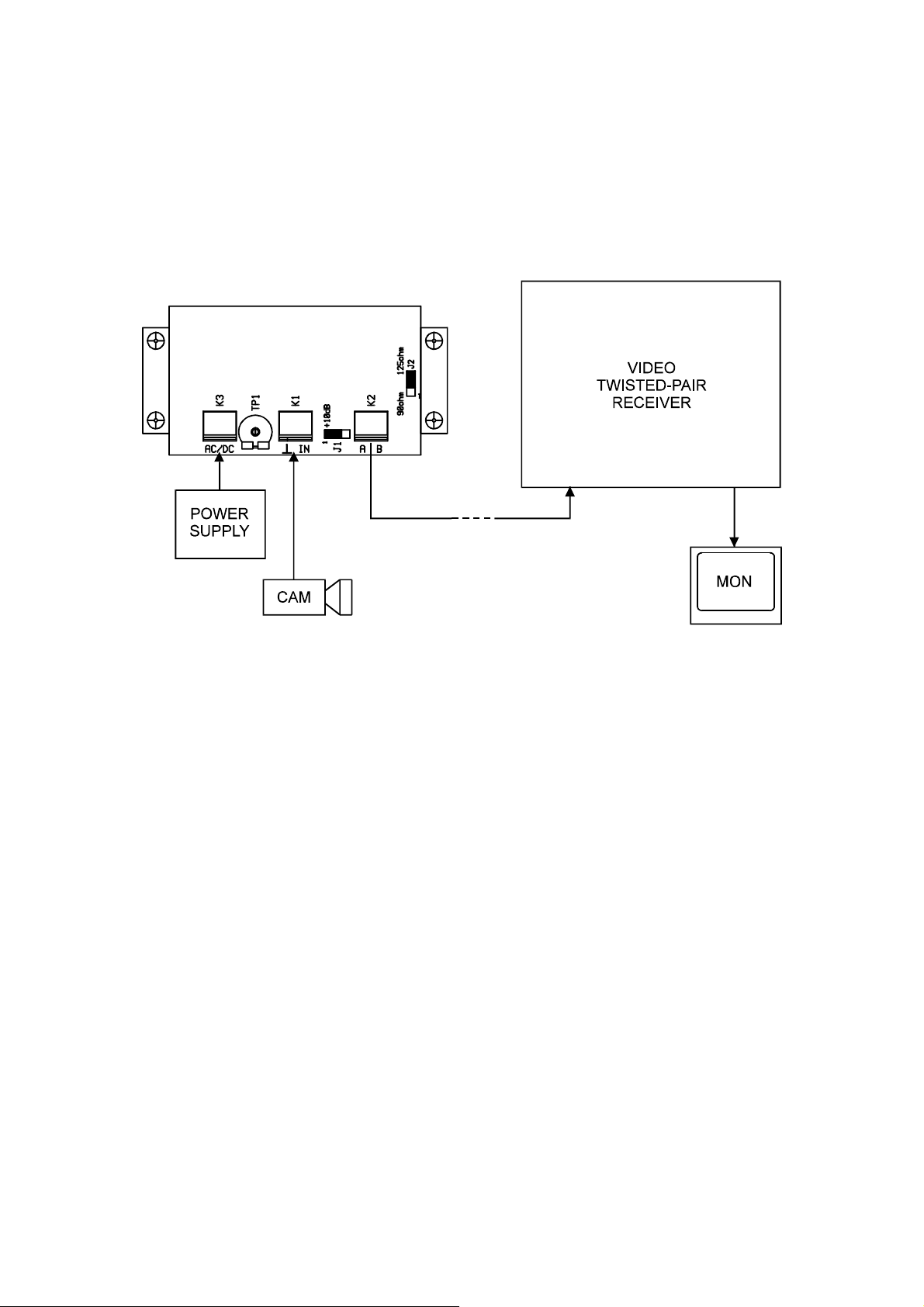
INSTALLATION
(1) Set the jumper J1 to 0 dB.
(2) Set the jumper J2 to correct position. (125 ohm for PE or PAPER, 90 ohm for PVC cable insulation)
(3) Connect the power supply unit (AC or DC) to the K3.
(4) Connect the video test generator (1 Vpp / 75 Ω) to the K1.
(5) Switch-on the power supply unit.
(6) Switch-on the video test generator.
(7) Check the positive video output signal between A and ⊥.
(8) Check the negative video output signal between B and ⊥.
(9) Switch-off the power supply unit.
(10) Switch-off the video test generator.
(11) Disconnect the video test generator.
(12) Connect the twisted-pair cable to the K2.
(13) Connect the video source (video camera) to the K1.
Note:
•Do not adjust the trimmer TP1.