Fullwat PDA-SS-C Series User manual

pure sine wave
ON
OF F
REMOTE
5V 2.1A
REMOTE
INPUT:
AC190-260V~
PDA-600SS-C / PDA-1000SS-C / PDA-1500SS-C / PDA-2000SS-C
Power DC-AC Inverter
COMBI BYPASS function:
VAC output + battery charger included
PDA-SS-C series

- 3 -
1. INTRODUCTION
Thank you for choosing our series Pure sine wave inverter with charger . It is a perfect combination with a pure
sine wave inverter, bypass transfer part and 3 stage battery charger. When the public power failure, it converts
the battery’s DC to AC to support the electrical appliances’ work. When the public power on, it auto. switches to
use main AC power and then auto 3 stage charging (constant current, constant voltage, floating charge) for your
battery, the transfer time is less than 15ms no any influence to your AC appliances.
2. FEATURES
• Fully auto. protection functions: earth leakage protection, reverse polarity, overload, over voltage, over
temperature, Iow voltage, short circuit.
• Transfer time between bypass and inverter mode is less than 15ms, no any influence in your appliance’s working
when public power off.
• Three LED indicators: Power, Fault, Charger.
• Pure sine wave output: THD<3%
• AVS protection function: Iow voltage, over voltage, time delay.
• Inverter and charger remote control function optional.
3. OPERATION ENVIRONMENT
For best operating performance, the inverter should be placed on flat surface, such as ground or other solid
surface, install the inverter in a location that is:
• DRY. Do not allow water and/ or other liquids to come into contact with the inverter. In all marine applications, do
not install the inverter below or near the waterline and keep the inverter away from moisture or water.
• COOL. Ambient air temperature should be between 30 ºF (-1ºC) non-condensing, and 105 ºF (40 ºC). Do not
place the inverter on or near a heating vent or any pieces of equipment which is generating heat above room
temperature. Keep the inverter away from direct sunlight, if at all possible.
• VENTILATED. Keep the area surrounding the inverter clear to ensure free air circulation around the unit, do not
place items on or over the inverter during operation. A fan is helpful if the inverter is operating at maximum power
outputs far extended periods of time. The units will shut down if the internal temperature exceeds operating
temperature and restart after it cools.
• SAFE. Do not use the inverter near flammable materiaIs or in any locations that may accumulate flammable
fumes of gasses.
4. PRODUCT INDICATION
4.1 Product dimension
PDA-600SS-C

- 4 -
PDA-1000SS-C
Indication
1
2
3
4
5
6
AC Outlet
Full power LED
Charging LED
Inverter LED
Fault LED
DC Input Terminal (Red-Positive)
DC Input Terminal (Black-Negative)
7
8
9
10
11
12
13
Cooling Fan
Inverter ON/OFF/REMOTE Switch
Remote control port
USB port 5V 2.1A
Charger ON/OFF/REMOTE Switch
Ventilation Hole
Chassis ground
14
15
16
17
18
19
AC input cable
DC cable with ring
DC Fuse
AC fuse
User Manual
Remote controller
PDA-2000SS-C
4.1 Product dimension
ON
OFF
REMOTE
5V
REMOTE
2.1A
INPUT:
AC190-260V~
1 2 7
6+ 6-
7
34 5
8
19
9
101112
1314
15
16
17
18
DC Cable with ring
DC Fuse
AC Fuse
User Manual

- 5 -
5. AVS PROTECTION FUNCTION
•
Lower voltage protection: When the public power is lower than 70V/170VAC, the inverter shall be shut down to
protect it. Once voltage increases to normal range. The inverter restarts automatically.
• Hlgh voltage protection: When the public power is too high, the inverter shut down and auto. restart once the
voltage is down to the normal range.
• Time delay: The restart after protection delay 17 seconds, the time delay function avoid the unit’s damage even
AC grid power failure frequently.
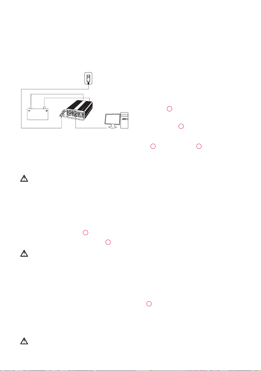
6. INSTALLATION
Note:
• You can use one or more batteries. Be best to use 100
Ah ar larger battery for long back-up time.
•
lf grld power available, AC bypass the lnverter & power-
for the e!ectrical appliances (“lnverter” mode ON by
switch ON the
4
). Also charge the battery / batteries.
• lf grid power failure, it converts the battery DC power to
AC power-for the electrical appliances. (must switch on
the “lnverter” mode
4
).
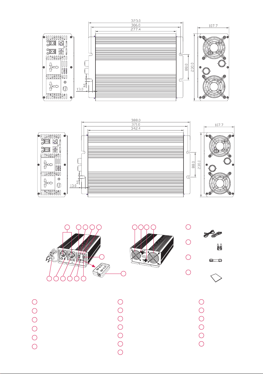
6.1 There are cables inside of packaging, use the cable connect the unit directly to the battery.
The input terminals on the rear side of the unit are Red-Posltive
6+
and Black-Negative
6-
. Connect the red
cable to the red terminal and to the positive pole of the battery. Connect the black cable to the black terminal
and to the negative pole of the battery. Make sure all connections are solid and secured. Poor connections
may cause overheat the cable and also shorten the battery backup time. (Ensure that the inverter and charger
mode are all OFF before connect to battery).
Warning
• The reverse polarity will burn the fuse or may cause the damage of the inverter. So pleae pay more attention
to it. The damage caused by wrong connection is not cover by our warranty.
•
The inverter must be connected only to batteries with a normal output voltage of 12 volts. The power source
can be a 12V battery or several 12V batteries connected in parallel / in series to increase the backup time. The
unit will not oparate from a 6 volt battery, and will sustain permanent damage if connected to a 24 volt battery.
• Keep ventilation when using batteries. Batteries may generate flammable gas during charging or discharging.
• Sparking may occur when connect the unit to the battery, make sure no flammable fumes present before
making any connections.
• Please use the DC cables
12
whlch lnside the packing to ensure best performance.
6.2 Connect the grounding terminal
7
to earth. lf you can, please do it to ensure safety.
Warning
Before use the inverter please provide a grounding cable. There Is a terminal fitted with a nut in the inverter’s output
panel. Please choose heavy duty, green insulated cable and driven into the ground at a depth of 1-2m or more.
6.3 Plug into the public power, the charger part effect, and charger LED on. It can charge for
your battery.
6.4 Plug your AC appliance into the inverter’s outlet
Make sure your appliance is turned off before connecting to the unit. Please turn your appliance on one by one.
Now your appliance are functioning. lf overload, the red LED
3
and the inverter shut down. To reset, reduce the
load and if your appliance required power within inverter’s rated power inverter shall restart automatically.
6.5 Use the remote function. (Only available with the remote controller)
Please connect the controller to the remote port on inverter. When using this function, turn the inverter or
charger switch button to ‘REMOTE’ option. You can control the inverter or charge part separately.
Warning
We advise that do not use the appliance whose power is more than 90% of the inverter’s rated power.
Although there is overload protection In inverter, it may damage the unit.
ON
OFF
REMOTE
REMOTE
5V2.
1A
INPUT:
AC190-260V~
Battery
Public power
Inverter unit
AC Load

- 6 -
7. PROTECTION FUNCTION
lt is designed with a universal protection circuit that provide added safety features not only for your AC appliances,
batteries but also for itself.
IV Auto.3 stage charge
Bypass and
Inverter Mode
Protection
Earth Fault Protection The inverter will shut down when the load has electric
leakage.
Low Voltage Alarm Alarm will activate when battery discharge to
10.6V/21.2V.
Low Voltage Protection The inverter will shut down when battery discharge to
10V/20V ( preven! damage to battery).
Over Voltage Protection The inverter will shut down when battery voltage is up
to 15.5V/31V.
Over Temperature Protection The inverter will shut down when overheat.
Overload Protection The inverter will shut down when the loading power
exceeds its rating power.
Short Circuit Protection The inverter shut down when output short circuit
happened.
Soft Start Circuit
Reverse Polarity Protection By fuse open.
Gradual voltage ramp-up during inverter
start-up This eliminates failed cold start under load.
Output that momentarily dips in voltage
and quickly recovers.
This eliminates most shutdown from momentary
overload.
Automatically Restart The inverter part automatically re-start when
overload remove.
Charger mode
protection Auto 3 stage battery charging
Stage 1. Constant Current- Rapid charge for the
battery with constant high current.
Fit for heavy-loaded condition.
Stage 2. Constant Voltage-Moderate charge for the
battery with constant voltage, this allows the battery
to well absorb the charge and maximum battery’s
life.
Stage 3. Floating Charge-After the battery charged
to around 99% full. The charger automatically
switches to “floating-mode” that keeping the battery
in well condition.

- 7 -
8. OPERATING TIPS
8.1 Rated Versus Actual Current Draw of Equipment
Most electrical tools, appliances and audio/ video equipments have labels that indicate the power
consumption in amps or watts. Be sure that the power consumption of the item you wish to operate is rated
within inverter wattage or less. (if the power consumption is rated in amps AC, simply multiply by the AC volts
to determine the wattage). The inverter (inverter mode) will shut down if it is overloaded. The overload must be
removed before the inverterrestarts. Resistive loads are the easiest for the inverter to run. However, larger resistive
loads, such as electric stoves or heaters, usually require more wattage than the inverter can deliver. lnductive
loads, such as TV’s and stereos, require more current to operate than do resistive loads of the same wattage
rating. lnduction motors, as well as sorne televisions, may require 2 to 6 times their wattage rating to start up. The
most demanding in the category are those that start under load, such as compressors and pumps. Testing is
the only definitive way to determine whether a specific load it can run. To restart the unit after shutdown due to
overloading, remove the overload if necessary, turn the power switch OFF then ON.
8.2.Power Tools and Microwave Ovens Won’t Start
Read the information panel on each power tool carefully to accurately determine the tool’s input wattage. The
output wattage is sufficient to operate most power tools and microwave ovens but remember that the power
needed to start the power tool may be as much a s 2 to 6 times of its continuous wattage required.
8.3.The AC output waveform of the inverter (inverter mode) is know as the “pure sinewave”.
Figure 1: Modified Sine Wave and Pure Sine Wave Comparison.
8.4.Battery’s Back up depends on the appliances which you will be used.
The batteries must provide between 10.5 and 15.5 volts DC (if 12V inverter) and must be able to supply the
necessary current to operare the load. The power source should be a well condltíon deep-cycle Lead-acid
battery. To obtaln a rough estimate of the current (in amperes) the power source must deliver, simply divide the
power consumption of the load (in watts AC) by 10.
Example: if a load is rated at 100 watts AC, the power source must be able to deliver: 100/10 = 10A 0n larger
applications the power source may be several batteries connected in parallel. It is important to make sure
the cables have enough size. This manual does not describe all of the possible type of battery configurations,
battery charging configurations and bnttery isolation conflgurations.
8.5 Batlery Charger
We recommend you use deep cycle batteries. lf you hear the elerm of low voltage protection, please stopping
to use it, when it is fully charged, you can use it again. Please plug into the public power to charge for the
battery.
The battery operation time dapends on the battery capacity (Ah) and the loading power (Watt).
The method to calculate the operetion time is:
Battery capacity (Ah) x input voltage (Y)/ loading power (W)
Example:
Battery capacity = 150Ah
Input voltage = 12V
Loading power = 600W
(150Ah x 12V)/600W = 3H

- 8 -
9. TROUBLESHOOTING
9.1
When public power failure and lnverter switch ON, the problem happened in the inverter mode
9.2 When public power on, the problem happened in bypass and charger mode
9.3 Other problems
10. CLEANING, CARE AND MAINTENANCE
Always disconnect the power inverter from the 12V/24V power source and the external appliances from the
socket before starting any cleaning or maintenance. Keep all air inlets and vents free of dirt and dust. Clean the
power inverter with a moistened cloth. Do not use abrasive utensils for cleaning. Store the power inverter in a dry
place, well ventilated and in a temperature range between 0ºC and 40ºC. Do not store in direct sunlight, near
heater, radiators or under moist and wet environment conditions.
Trouble Possible cause Suggested remedy
No AC
output
Red LED lit,
green LED not lit
or beep sound
alarm
Battery over discharged, low battery
protection Change the battery or charging for it
Over temperature protection
Remove or reduce load, wait for inverter to cool
Overload protection Remove or reduce load or use more big power
inverter
Short circuit protection Reduce load or remove short circuit
No AC
output
Red and green
LED not lit Fuse burned Change fuse or contact technician for support
No AC
output
Red and green
LED not lit
Fuse burned Change fuse or contact technician for support
PCB broken Contact seller for repair or change
Battery’s defective or poor connection Change battery or re-connect the battery
Earth fault protection Unplug the fault load
Strong collision cause the circuit loosen Contact seller for repair or change
Battery run time is less than
expected
AC loads power consumption is higher
than the reated power
Use a larger battery or conect more batteries in
parallel to increase the back up time
Battery is old or defective Replace the battery
Battery over discharge Charge for the battery
Power dissipation caused by the too
long or thin cable Use mor shorter /heavier DC cables
Trouble Possible cause Suggested remedy
When the public power is
available, inverter mode can’t
be switch to charge mode
Poor AC wire connection Tighten connection or re-connect the AC
power
Built in fuse burned
Change fuse or contact technician for support
Inverter beeps long time but
still on working
Battery will be fully charged soon It will be auto.stop the charge or you switch off
charger mode
AC input voltage under 170V/70V Stop to use it or switch off the charger mode or
adjust AC voltage
Using time too long, high temperature Switch off 10 minutes to cool down
Trouble Possible cause Suggested remedy
Cooling fan not working Ir will working when in charge mode, fully
charged it will aio stop It is normal
Cooling fan not working
When AC main power failure, it should
work in inverter mode, but it is not
working
Contact seller for repair or replace
Inverter output shows low
voltage
Reading voltmeters and can’t get
accurate data Use a true RMS reading voltmeters

- 9 -
11. Disposal
Old electrical appliances are recyclable. Do not dispose them in the domestic waste! Separately deliver
these in a valuable material collection point. Dispose the packing material environmental friendly. Please
give cardboard and paper to te waste paper, foils to a valuable material collection point.
12. ESPECIFICATION
13. WARRANTY AND SERVICE AGREEMENTS
This warranty covers only manufacturing defects. The appliance must not be modified or altered in any way with
regards to both form and function. This warranty does not apply in case of improper usage that falls beyond
normal use as indicated in the user’s manual or if there is damage caused by force majeure (e.g. natural
disaster). Only clean and intact appliances will be accepted for warranty and non-warranty repair. Tje standard
warranty period is covered as legally terms settled starting from the purchase date. In order to make a warranty
claim, this warranty card must be submitted along with proof of purhcase, including the model number,
purchase date and a dealer’s stamp.
Model number: ...............................................................
Purchase date:................................................................
Dealer’s stamp and signature: ........................................
Date of warranty claim:...................................................
Defect(s) noted: ..............................................................
14. ICON INDICATION
MODEL PDA-600SS-C PDA-1000SS-C PDA-1500SS-C PDA-2000SS-C
Output
Rated power 600W 1000W 1500W 2000W
Surge power 1200W 2000W 3000W 4000W
AC output 220±10% 50Hz or 110V ± 10% 60Hz (refers to product’s label)
Wave form Pure sine wave
USB port 5V 2.1A (optional)
Input
DC input 12V (10-15V) or 24V 21-30V)
AC input range 170-250V (220V) or 70-150V (110V)
Charger
Max. Current 12V 10A 15A
24V 5A 7A
Charge way Constant current, constant voltage, floating charge (Auto.3 Stage)
Transfer time <15ms <25ms
Protection
function
Overload 630-700W 1100-1200W 1600-1700W 2100-2200W
Over temperature >60ºC auto.shutdown
Other earth leakage, polarity reverse,over voltage, low voltage, overload,
overheat, short circuit
AVS protection low voltage, over voltage, time delay

Agente importador
A48.139.786
UKAI S.A.
Ribera de Elorrieta, 7C
48015 - Bilbao - SPAIN
Designed in EU - Made in PRC
fullwat.com
This manual suits for next models
4
Table of contents
Other Fullwat Inverter manuals

Fullwat
Fullwat PDA500SS User manual

Fullwat
Fullwat PDA1500-STATION Series User manual

Fullwat
Fullwat PDA-D Series User manual

Fullwat
Fullwat PDATROLY-1000 User manual

Fullwat
Fullwat PDA300S User manual

Fullwat
Fullwat PDA400 User manual

Fullwat
Fullwat PDA5500-STATION User manual

Fullwat
Fullwat PDA300-LC Series User manual