Must be observed: Hazard and safety information . . . . . . 3
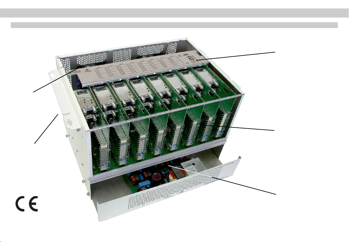
Figure of X-8 twin . . . . . . . . . . . . . . . . . . . . . . . . . . . . . 2
1 Pictographs . . . . . . . . . . . . . . . . . . . . . . . . . . . . . . . . . . 3
2 Hazard and safety information . . . . . . . . . . . . . . . . . . . 3
2.1 Installation instructions . . . . . . . . . . . . . . . . . . . . . . . . . . 3
2.2 Opening the housing . . . . . . . . . . . . . . . . . . . . . . . . . . . 4
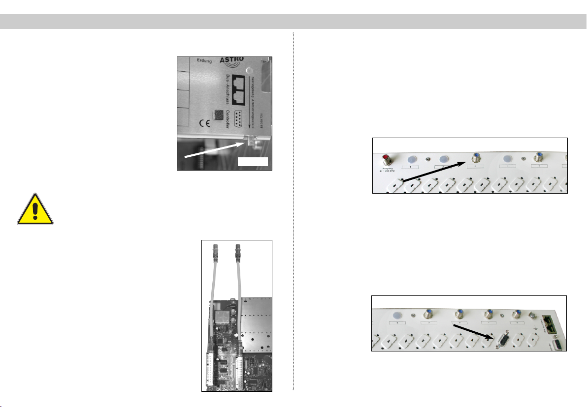
2.3 Potential equalization and grounding . . . . . . . . . . . . . . . 5
3 Preparing the base unit . . . . . . . . . . . . . . . . . . . . . . . . . 5
3.1 Mounting bracket . . . . . . . . . . . . . . . . . . . . . . . . . . . . . . 5
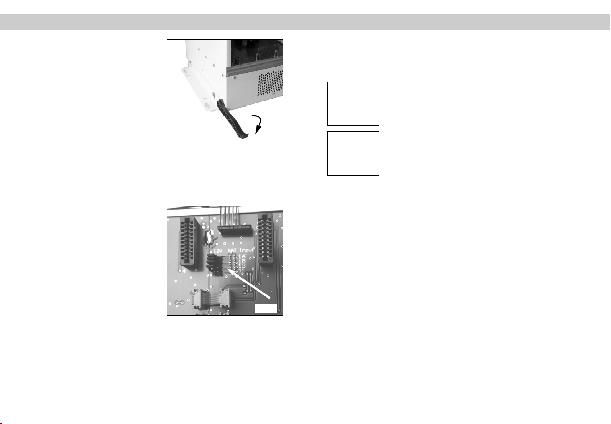
3.2 Changing thepower supply . . . . . . . . . . . . . . . . . . . . . . 5
3.3 LNB remote supply . . . . . . . . . . . . . . . . . . . . . . . . . . . . 6
4 Configuration of X-8 twin . . . . . . . . . . . . . . . . . . . . . . . . 6
4.1 Setting bus address . . . . . . . . . . . . . . . . . . . . . . . . . . . 6
4.2 Temperature . . . . . . . . . . . . . . . . . . . . . . . . . . . . . . . . . . 6
5 Installing plug-in cards . . . . . . . . . . . . . . . . . . . . . . . . . 7
5.1
Cards with SAT tuner
. . . . . . . . . . . . . . . . . . . . . . . . . . . . 7
5.2 Cards for terrestrial conversion . . . . . . . . . . . . . . . . . . . 7
5.3 (De-) Modulator cards . . . . . . . . . . . . . . . . . . . . . . . . . . 7
5.4 Uninstalling plug-in cards . . . . . . . . . . . . . . . . . . . . . . . . 8
6 Configuration of all plug-in cards . . . . . . . . . . . . . . . . . . 8
7 Level adjustment . . . . . . . . . . . . . . . . . . . . . . . . . . . . . . 8
8 Configuration SAT-distribution board . . . . . . . . . . . . . . . 9/10
9 Technical specifications . . . . . . . . . . . . . . . . . . . . . . . . . 11
Accessories . . . . . . . . . . . . . . . . . . . . . . . . . . . . . . . . . . 13/14
Contents 1 Pictographs and safety information
3
1Pictographs and safety information
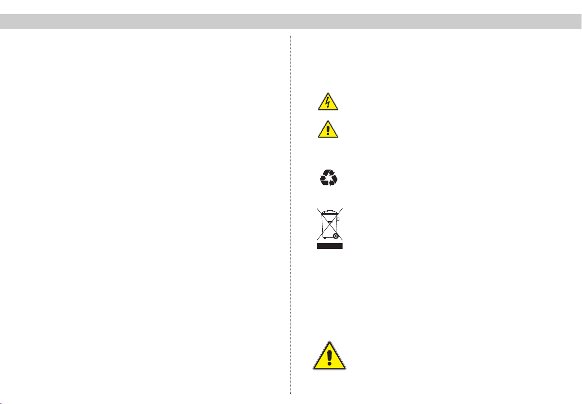
Pictographs are icons with specific meanings. The follo-
wing pictographs are used in the installation and opera-
ting instructions:
Warns about situations in which there is danger of lethal
injury due to hazardous electrical voltage and non-com-
pliance with these instructions.
Warns about various hazards to health, environment and
materials.
This is a general information symbol.
Recycling: All of our packaging materials (packaging,
identification sheet, plastic foil and bag) are fully recyclable.
Electronic equipment is not household waste – in accordan-
ce with directive 200/96/EC OF THE EUROPEAN
PARLIAMENT AND THE COUNCIL of 27th January 2003 on
used electrical and electronic equipment, it must be disposed
of properly. At the end of its service life, take this unit for dis-
posal at a relevant official collection point.
2 Hazard and safety information
2.1 Installation instructions
The device may be installed only in dry rooms and on
vertical surfaces.
Installation location: indoors
The device can be fastened to the wall using the supplied
mounting materials.
☞
Must be observed: Hazard and safety information . . . . . . 3
Figure of X-8 twin . . . . . . . . . . . . . . . . . . . . . . . . . . . . . 2
1 Pictographs . . . . . . . . . . . . . . . . . . . . . . . . . . . . . . . . . . 3
2 Hazard and safety information . . . . . . . . . . . . . . . . . . . 3
2.1 Installation instructions . . . . . . . . . . . . . . . . . . . . . . . . . . 3
2.2 Opening the housing . . . . . . . . . . . . . . . . . . . . . . . . . . . 4
2.3 Potential equalization and grounding . . . . . . . . . . . . . . . 5
3 Preparing the base unit . . . . . . . . . . . . . . . . . . . . . . . . . 5
3.1 Mounting bracket . . . . . . . . . . . . . . . . . . . . . . . . . . . . . . 5
3.2 Changing thepower supply . . . . . . . . . . . . . . . . . . . . . . 5
3.3 LNB remote supply . . . . . . . . . . . . . . . . . . . . . . . . . . . . 6
4 Configuration of X-8 twin . . . . . . . . . . . . . . . . . . . . . . . . 6
4.1 Setting bus address . . . . . . . . . . . . . . . . . . . . . . . . . . . 6
4.2 Temperature . . . . . . . . . . . . . . . . . . . . . . . . . . . . . . . . . . 6
5 Installing plug-in cards . . . . . . . . . . . . . . . . . . . . . . . . . 7
5.1
Cards with SAT tuner
. . . . . . . . . . . . . . . . . . . . . . . . . . . . 7
5.2 Cards for terrestrial conversion . . . . . . . . . . . . . . . . . . . 7
5.3 (De-) Modulator cards . . . . . . . . . . . . . . . . . . . . . . . . . . 7
5.4 Uninstalling plug-in cards . . . . . . . . . . . . . . . . . . . . . . . . 8
6 Configuration of all plug-in cards . . . . . . . . . . . . . . . . . . 8
7 Level adjustment . . . . . . . . . . . . . . . . . . . . . . . . . . . . . . 8
8Configuration SAT-distribution board . . . . . . . . . . . . . . . 9/10
9 Technical specifications . . . . . . . . . . . . . . . . . . . . . . . . . 11
Accessories . . . . . . . . . . . . . . . . . . . . . . . . . . . . . . . . . . 13/14
Contents 1 Pictographs and safety information
3
1 Pictographs and safety information
Pictographs are icons with specific meanings. The follo-
wing pictographs are used in the installation and opera-
ting instructions:
Warns about situations in which there is danger of lethal
injury due to hazardous electrical voltage and non-com-
pliance with these instructions.
Warns about various hazards to health, environment and
materials.
This is a general information symbol.
Recycling: All of our packaging materials (packaging,
identification sheet, plastic foil and bag) are fully recyclable.
Electronic equipment is not household waste – in accordan-
ce with directive 200/96/EC OF THE EUROPEAN
PARLIAMENT AND THE COUNCIL of 27th January 2003 on
used electrical and electronic equipment, it must be disposed
of properly. At the end of its service life, take this unit for dis-
posal at a relevant official collection point.
2 Hazard and safety information
2.1 Installation instructions
The device may be installed only in dry rooms and on
vertical surfaces.
Installation location: indoors
The device can be fastened to the wall using the supplied
mounting materials.
☞