ASTRO X-5 twin B User manual


LNB remote current sup-
ply max. 250 mA
SAT intermediate
frequency input
920–2150 MHz
2
1 Illustrations
he X – 5 twin is CE certified and complies
ith all relevant EN standards.
hanges and printing errors reserved.
ersion: May 2004
X-5 Basis twin/AV X-5 Basis twin/BA
X-5 Basis twin/B or X-5 Basis twin/BA
Level adjuster
A
B
Loop-through
outputs
SAT intermedi-
ate frequency
920–2150 MHz
External inputs
47–2150 MHz
EX1
EX2
up to
EX10
10 (Sub-D) AV – inputs
Busadapter BA 2
Socket for
PC programming
or KC 3 controller
Y
X
HF output
87,5–862 MHz

3
1 Illustrations
Power supply
Socket for
PC programming
or KC 3 controller
Output level adjuster for each
channel group

Read carefully: Hazard and safety information .........................Page 5/6
1 Illustrations ...............................................................................Page 2/3
2 Pictograms and safety information...............................................Page 4
3 Description....................................................................................Page 6
4 Features .......................................................................................Page 6
5 Connecting to SAT equipment......................................................Page 7
5.1 LNB supply ............................................................................Page 7
5.2 Internal cabling ......................................................................Page 8
5.3 Grounding ..............................................................................Page 9
6 Connecting to subscriber network ...............................................Page 9
7 Connecting and commissioning ..................................................Page 9
8 Programming ...............................................................................Page 9
9 Level adjustment X-5 twin .........................................................Page 10
10 Grounding example ...................................................................Page 11
11 Sample configurations ..........................................................Page 11/12
12 Technical data X-5 twin .............................................................Page 13
13 Accessories........................................................................... Page 14/15
Contents Contents
4
2 Pictograms and safety informatione
Pictograms are icons with specific meanings. The following pictograms are
used in the installation and operating instructions:
Warns about situations in which there is danger of lethal
injury due to hazardous electrical voltage and non-compli-
ance with these instructions.
Warns about various hazards to health, environment and
materials.
This is a general information symbol.
Recycling: All of our packaging materials (packaging, identi-
fication sheet, plastic foil and bag) are fully recyclable.
Electrical scrap must not be placed in household refuse; it
must be disposed of by means of a special waste recycling
company. If you
have any questions about waste disposal, your local envi-
ronmental agency would be glad to give you further infor-
mation about recycling.
Hazard and safety information:
Power supply:
•Check the 230V operating voltage of the equipment with
the mains supply present.
•Install the power cable so that it cannot be tripped over.
Installation location:
The permissible ambient temperature is 0 … 50°C
☞☞

Opening the housing or changing plug-in cards:
Danger from electrically live elements
There is also danger of injury after disconnecting the power sup-
ply due to electrically live elements.
Danger of damage to or destruction of components
Before opening the housing:
Be sure to disconnect the power plug.
Do not service during thunderstorms.
Read very carefully:
DIN VDE 0701, Part 1 and 200, Repairs EN 50 083 – Part 1,
Security Requirements
The device must only be opened by authorized personnel.
The device must be repaired only by authorized personnel or by
sending the device to ASTRO with an exact description of the fault.
For your safety:
Read the above regulations and advices carefully. Install the
SAT equipment according to the safety requirements.
Observe regulations concerning grounding and potential equal-
ization (EN 50083 Part 1). Replace the power cables only with
an original part power cable. Replace fuses only with those of
the same type, value and melt characteristics.
T 630 mA L IEC 60127-2 / III.
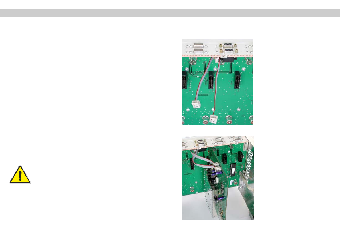
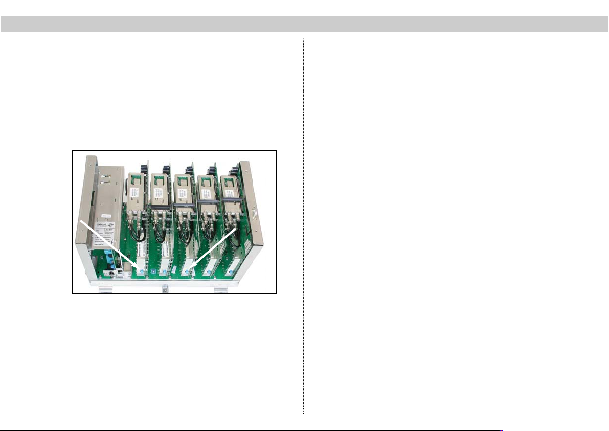
The mains fuse is located on the power unit plug-in card and can
be removed only if this card is first removed from the device.
Observe all safety instructions carefully!
Warning:
When the device is installed in places such as storage areas
and roof trusses, it must be ensured that the permitted maxi-
mum ambient temperature of 50°C is maintained. Beware of
condensation!
Because of fire hazard due to lightning, it is recommended that
all mechanical parts (e.g. X-5 twin, equipotential busbars, dis-
tributors, etc.) be mounted on a non-combustible base.
Combustible materials include wooden beams, wooden boards,
plastics, etc.
Operating safety:
The ambient temperature must not exceed 50°C.
Maximum LNB current supply: 250 mA
5
Installation is permitted only in rooms that maintain the per-
mitted ambient temperature even in changing climatic condi-
tions (away from heat radiation and other heat sources).
The device must not come into contact with splashing or
dripping water. Containers with liquid must not be placed on
the device.
Install on vertical surfaces only.
Keep vents free (30cm above and below).
The equipment must be well ventilated (installation in unven-
tilated cabinets or alcoves is not permitted). It is therefore
important that the vents are never covered.
If there is condensation, wait until the device is completely
dry.
If auxiliary fans are used with the X-5 twin for convection to
maintain the permitted ambient temperature range, it must
be ensured that in the event of fan failure the device is dis-
connected from the power supply by means of appropriated
measures in order to prevent damage to the device.
Effects of heat
Exposure to excessive heat, the accumulation of heat, or
operating the device above the permitted ambient tempera-
ture negatively influences the service life of the device and is
a source of danger (fire hazard!).
2 Hazard and safety information 2 Hazard and safety information

3 Description of X-5 twin
The X-5 twin device consists of a motherboard with sockets
for a power unit and up to 5 plug-in cards.
The input and output distribution field is integrated on the
motherboard. The required input polarization / band (X or Y)
is assigned to each card by a software command. The input
signals are available at the SAT loop-through outputs for
further X-5… processing units.
Additionally, ten further polarizations / bands can be con-
nected to the external inputs “EX 1” to “EX 10”. To do this,
you have to disconnect the tuner connecting cable of the
twin cards concerned from the motherboard and connect it
to the external input “EX 1” to “EX 10”.
Warning! LNC current supply for “EX 1” to “EX
10”must be connected separately.
6
4 Features
HSAX–5 twin basis device:
●Processing of up to 10 channels per base unit,
which means space saving for installation
●12 inputs, 2 of them switchable, for individual input signal processing
●Combination of single and twin cards possible
●Future – proof, because a hybrid operation of digital,
analog and terrestrial cards in a single basis unit is possible.
HSAX–5 twin / B basis device:
●Processing of up to 10 channels per base unit,
which means space saving for installation
●12 inputs, 2 of them switchable, for individual input signal processing
●including bus adapter BA 2
●Combination of single and twin cards possible
●Future – proof, because a hybrid operation of digital,
analog and terrestrial cards in a single basis unit is possible.
HSAX–5 twin / AV basis device:
●Processing of up to 10 channels per base unit,
which means space saving for installation
●12 inputs, 2 of them switchable, for individual input signal processing
●10 AV – inputs (Sub-D)
●Combination of single and twin cards possible
●Future – proof, because a hybrid operation of digital,
analog and terrestrial cards in a single basis unit is possible.
HSAX–5 twin / BA basis device:
●Processing of up to 10 channels per base unit,
which means space saving for installation
●12 inputs, 2 of them switchable, for individual input signal processing
●10 AV – inputs (Sub-D)
●including bus adapter BA 2
●Combination of single and twin cards possible
●Future – proof, because a hybrid operation of digital,
analog and terrestrial cards in a single basis unit is possible.
3 Description 4 Features

In all cases, the great advantage is that suitable, existing
tree structures in the buildings can continue to be used.
No special network structures and therefore construction
measures are required.
Digital reception is possible only with a cable SET-TOP
BOX (e.g. ASTRO ASR 530).
Configuration software
Using the optionally available configuration software
(Windows-compatible, including connection cable and
adapter), all headend parameters can be set simply and
clearly and then saved.
Laborious searching for the right input SAT intermediate fre-
quency is no longer necessary because all program para-
meters of the commonest satellites are stored in a data-
base. The user only has to enter the satellite, the LNC
oscillator frequency, the desired program and the output
channel. All other parameters are read from a database.
The user can update the databases or download the latest
data from the ASTRO server via the Internet.
5 Connecting to SAT equipment
Cabling:
•Connect the SAT signals from the LNB to inputs X and Y.
•The internal distribution field routes the input signals
without noticeable transmission loss to the SAT loop-
through outputs (forwards SAT signals to the next X-5…
device). Because of the signal quality, maximum 3 base
units should be cascaded
•Additional feed of 10 polarizations / bands via inputs
“EX 1” to “EX 10”.
Note:
•There is no LNB supply voltage at inputs “EX 1” to “EX 10”!
•Use quality SAT components and SAT compatible
coaxial cable.
•Install the F-connectors carefully and correctly.
•If not used, close the SAT loop-though outputs with 75-
Ohm terminal resistance.
Important:
The above advice is very important. Many errors are often
due to incorrect cabling and have a strong influence on any
subsequent cascading
5.1 LNB supply
•Switching on/off the LNB power supply via software
(chapter “Programming”)
The total current must not exceed 250 mA.
•LNB power supply is short-circuit-proof.
•Exceeding the maximum feed current results in a
forced switch-off of the LNB supply voltage.
•Switch-off of power supply of cascaded devices (LNB OFF)
•Inputs “EX 1” to “EX 10” have no LNB power supply option.
7
4 Features 5 Connecting
☞

8
5.2 Internal cabling of X-5 twin ...
Important
Installation sequence of the HSA X-Plug-in cards:
Tuner inputs of the plug-in cards, which are installed nea-
rest to the power supply, have to be connected decrea-
singly, starting with “EX10”. The tuner input of the following
plug-in card has to be connected in order to “EX9”, so that
the furthest to the power supply
plug-in card is connected to “EX1”!
If plug-in cards have an indentation for cable run, the “EX”-
input cables have to be led through them.
Guide the cables to the “EX1”- to “EX10”- positions tight
along the left side wall. Therefor, if possible, you have to
wind up the cable close to the respective tuner input. The
cable has to be stabilized with the cable straps, added to
the plug-in card.
Warning:
Cables never might get into the openings of the power sup-
ply, or become pushed into the openings.
Note:
Changing the modules may be done only by authorized
personnel according the regulations. The hazard and
safety information in these installation instructions and
the safety regulations in accordance with DIN VDE
Directive 0701, Part 1 and 200 (repairs) must be observed.
5 Connecting 5 Connecting
Modulator cards:
With the X-5 basis twin / AV and the
X-5 basis twin / BA, there is the pos-
sibility to connect modulator- and
demodulator-cards. They are con-
nected via Sub-D socket. The instal-
lation and connection of such a card
is described below:
1. Remove the dummy covering of
the respective slot and fit in the sock-
ets, delivered with the cards.
2. Plug-in the modulator- or demodu-
lator-card and put on the sockets
considering the correct direction.

5.3 Grounding
•The equipment must be correctly grounded and
installed in compliance with EN 50 083 Part 1.
6 Connecting to subscriber network
Cabling:
•Integrated coupling field in X-5 twin... routes the 5
channel pairs to the HF output socket.
•Connect the X-5 twin… devices together using
distributor set components.
•Connect to subscriber network.
Note:
•Connect plugs carefully and correctly.
•Use only quality components.
7 Connecting and commissioning
Check:
•All safety instructions in Chapter 2 observed (p. 4)
•Installation and grounding as in Chapter 5 (p. 8)
•Connecting to SAT equipment as in Chapter 6 (p. 9)
•
Connection to distributor network as in Chapter 7 (p. 10)
•After connecting the mains cable to the power supply,
the device is in operation.
8 Programming
Connecting the KC 3 programming device:
•
Plug-in KC 3 programming device via Sub-D connection
•After approx. 10 seconds, the start menu appears on
the display
9
6 Connecting and commissioning 8 Programming
☞
HSA X-Serie
Version X.XX
(Weiter mit < >)
LNC-Power
XY-Eingang AUS
Busadresse 241
Passwort AUS
04: TWIN1-A E02
SAT-Freq 1432 MHz
AusFreq 362,2 MHz
Kanal S28
The KC 3 software is separated in 3 main sections:
1. Version number:
The menu “version number” is displayed only after the KC
3 device is connected. Please specify this number
when contacting our service staff. You can reach this
menu only after disconnecting and reconnecting the KC 3.
Start input by pressing the ←or →- keys.
2. Main menu:
•Setting the LNC – power supply:
Select line 2 with the ↑or ↓- arrow – keys; use the
←or →- arrow keys to switch on / off the LNB power
supply and then save your settings.
•Changing the bus address:
Select line 3 with the ↑or ↓- arrow – keys; use the
←or →- arrow keys to change the address sequentially
or use the keypad.
•Password function:
Select line 4 with the ↑or ↓- arrow – keys; use the
←or → - arrow keys to activate / deactivate the
password function.
•Selecting a slot:
Select line 1 with the ↑or ↓- arrow – keys; use the
←or →- arrow keys to move to the next slot
3. Submenu of the plug-in cards:
In the submenu of the plug-in cards, the type of card, the
chosen tuner, the input parameters and the output para-
meters of the installed card are displayed.
All important parameters can be adjusted.
Follow the operating instructions of the respective plug-in card

9 Level adjustment
The optimal output level (measured at the output of the
base device) is as follows:
•100 dBµV for PAL channels
•90 dBµV for QAM channels
•96 dBµV for radio (FM) channels
To enable the setting, the level regulators of the individual
plug-in cards are set accordingly.
Note:
Under no circumstances should a skewed position be set to
compensate outgoing cable attenuation by means of differ-
ent level adjustment of the plug-in cards! For this purpose
use output coupling field U-901 (order no. 380 190) or VZN
8 (order no. 380 191).
9 Level adjustment
10
☞level adjustment
☞

10 Grounding example 11 Sample configurations
11
Grounding example
or installation and grounding accessories, see the ASTRO catalog
16 mm2Cu
4 mm2Cu
Grounding rail
5030
Grounding rail
5030
☞
Example I
Additional feed of foreign programs (EUTELSAT) into the cable network
SAT 75/90
SBX 645
to distributor network
BC (BK)
Broadband
cable
HMW 13
CTB (HÜP) Cable
Transition Box

12
11 Sample configurations 11 Sample configurations
SAT 75/90
SBX 645
GUT 103
SEV 200 DIG
HFT 4
HFD 2
Example II
xtension 1 Cable Solution Example III
New installation, 20 channels + terrestrial feed
terr. equipment
SAT 75/90
SBX 645
to distributor network
HFT 4
(Highband)
(Lowband)

12 Technical data for basic devices
13
Type X-5 twin X-5 twin B X-5 twin AV X-5 twin BA
Order number: 330461 330840 330680 330690
SAT - Inputs
switchable inputs 22 2 2
external inputs 10 10 10 10
polarizations 12 12 12 12
AV - inputs –– –– 10 10
Busadapter BA 2 –– 1 –– 1
common data
LNC - supply [V] 14/18, max. 250 mA via SAT-input X bzw. Y
Voltage supply [V~] 230, 50/60 Hz
Power consumption [VA] 95
temperature range [°C] 0 … +50
Dimension (BxHxT) [mm] 372 x 276 x 167

13 Accessories
14
X-BC … Buscontroller
X- BC 1
The headend bus controller is for centrally setting all bus-capable headend devices via PC. Maintenance and
e-programming of already set up headends can be done via modem.
Operation is only possible with the HE programming software!
●Control of up to 240 bus-capable headend devices
●Can be individually set, from ring tone to call reception (i.e. parallel operation with other terminals is possible)
●8-digit identification code protects against unauthorized remote access
●Internal monitoring timer protects against excessive telephone charges (automatic hang-up if there is no communicati-
on within five minutes)
●Operating software can be updated via serial interface (i.e. software updates without installation work)
X-BC 2 – additional features
●Remote control via GSM modem
●Error messaging via SMS (alarm messaging to max. 3 phone numbers)
●4 time partitions can be set (for each time partition 6 switching times can be defined)
X- BC 1
X- BC 1 Rückseite/
KC 3
Typ X-BC 1 X-BC 2
Order no. 330401 330400
Supply voltage [DC]
6 V
through plug-in power supply unit
(230V~/50Hz)
Current consumption [mA] 35
Permitted ambient temp. [°C] -15 … +50
KC 3 external programming unit for programming all setting parameters (order no.: 330 650)

13 Accessories
15
he HE programming software (order no. 330 630) facilitates programming X-5…V16
eadend systems with a PC or laptop computer. The user can store all headend para-
meters in the office prior to commissioning, for example:
●
received satellite
●
SAT programs
●
output channel
●
program video and audio parameters on PC or laptop and save to storage media.
he user also has the option of remotely programming and maintaining headend
evices via modem. These added features save the network operator service costs,
or example when changes occur in transponder assignments. They mean rapid
esponse in the event of processing card failure (replacement signal switching).
he software supports the replacement signal switching. To activate replacement
ignal switching, the network operator only needs to select the “failed module” and the
replacement module (redundancy).” Manually reconfiguring the operating parameters
or the redundancy module is not required. The following processes are performed
utomatically:
●
deactivating (HF) the failed module.
●
copying all operating parameters of the failed module to the redundancy module.
●
activating (HF) the redundancy module.
With the HE programming software up to twenty X-5…V16 headend devices can be
aved in a configuration file. From the menu item “Display unit” the user has the option
f accessing the program parameters of an already existing headend and can then easi-
y edit and modify. Current program satellite assignments are stored in their own ”SAT
rogram files.” The user can update and change these files when needed. ASTRO
ffers updating program assignments of the most common satellites via the Internet.
HE programming software
On - site –
during the commissioning –
the configuration data just have to
be transferred to the headend-sys-
tem via delivered zero-modem
cable and PC-X-5/10-adapter, or
via optional bus-system.
So the configuration of many pro-
grams is perfectly possible during
several seconds.

ASTRO Strobel
Kommunikationssysteme GmbH
Olefant 1–3
D-51427 Bergisch Gladbach (Bensberg)
Tel. +49 (0 ) 2204 / 405-0
Fax +49 (0 ) 22 04 / 405 10
e-mail: [email protected]
http://www.astro-kom.de
This manual suits for next models
3
Table of contents