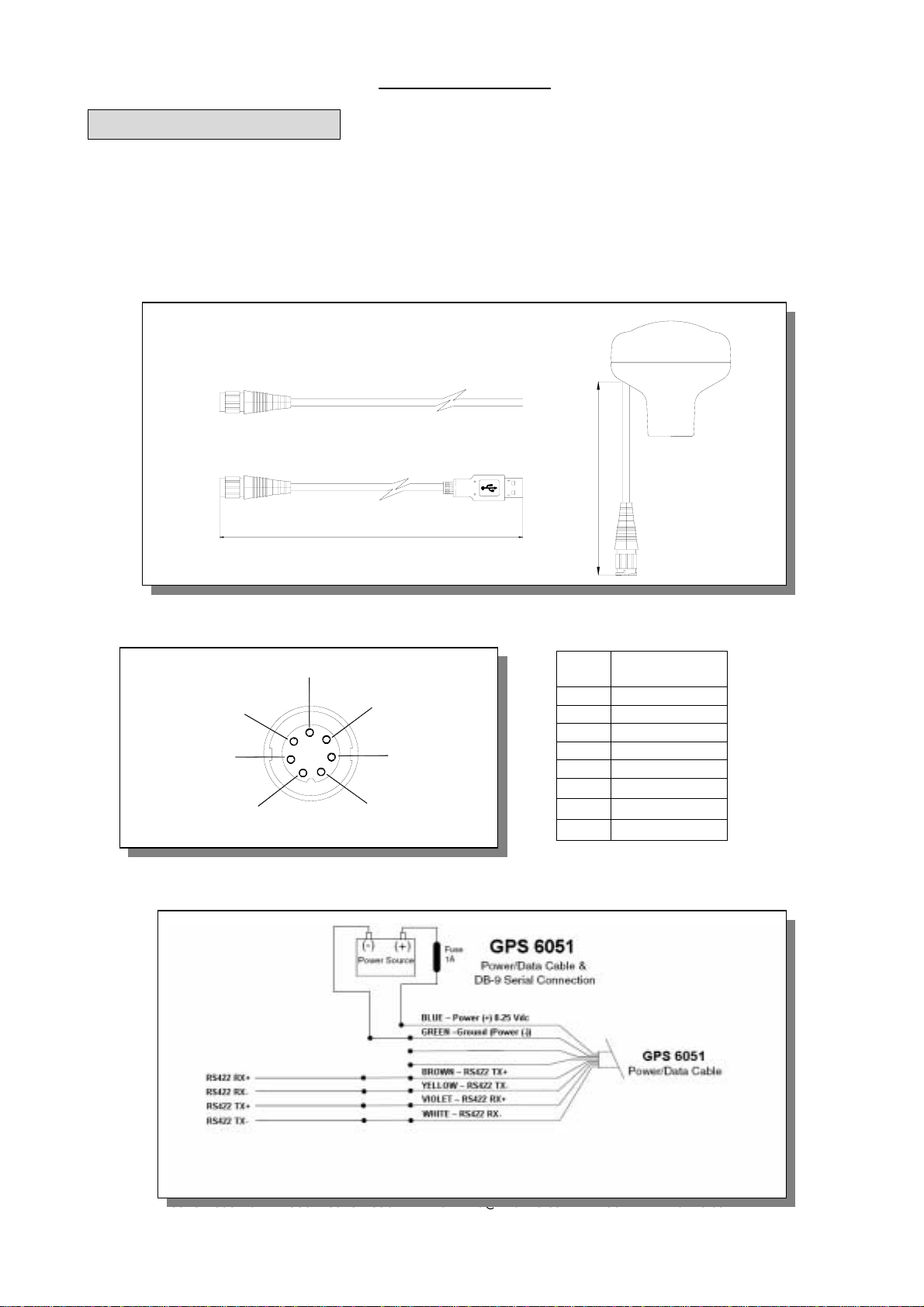
Marine GPS GPS-6051 Operating Manual
Rikaline
Rikaline International Corp. 14F, 171, ChengGong Rd., Sanchong City, Taipei 241, Taiwan, R. O.C
Tel:
++886
2
8973-189
9
Fax:
++886
2
8973-
1896
E-Mail:
[email protected]w web: www.rikaline.com.tw
5
1. Introduction
1.1 Overview
The
Rikaline
GPS-6051 Marine GPS is a total solution GPS receiver, designed based on SiRF Star II
Architecture. This positioning application meets strict needs such as car navigation, mapping, surveying,
security, agriculture and so on. Only clear view of sky and certain power supply are necessary to the unit. It
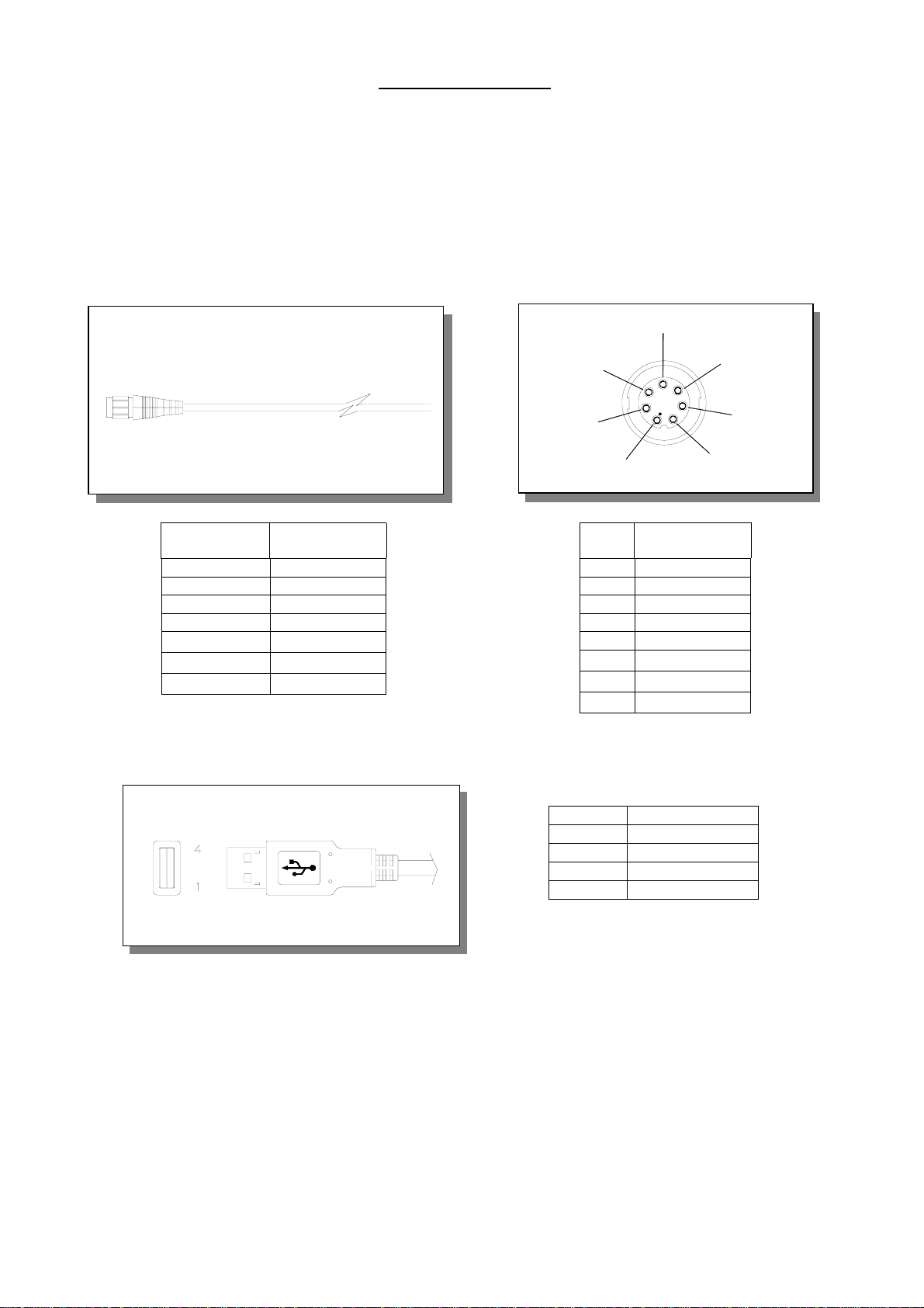
communicates with other electronic utilities via compatible dual-channel through RS-422 or USB interface and
saves critical satellite data by built–in backup memory. With low power consumption, the GPS-6051 tracks up
to 12 satellites at a time, re-acquires satellite signals in 100 ms and updates position data every second.
Trickle-Power allows the unit operates a fraction of the time and Push-to-Fix permits user to have a quick
position fix even though the receiver usually stays off.
1.2 Features
The GPS-6051 provides a host of features that make it easy for integration and use.
1. SiRF Star II chipset with embedded ARM7TDMI CPU available for customized applications in firmware.
2. High performance receiver tracks up to 12 satellites while providing first fast fix and low power
consumption.
3. Differential capability (Optional model) utilizes real-time RTCM corrections producing 1-5 meter position
accuracy.
4. A rechargeable battery sustains internal clock and memory. It is recharged during normal operation.
5. User initialization is not required.
6. Optional communication levels, RS-422 or USB meet various applications.
7. FLASH based program memory: New software revisions upgradeable through serial interface.
8. Built-in WAAS demodulator (Optional for special demand).
9. Water proof designed for all weather.
1.3 Technology specifications
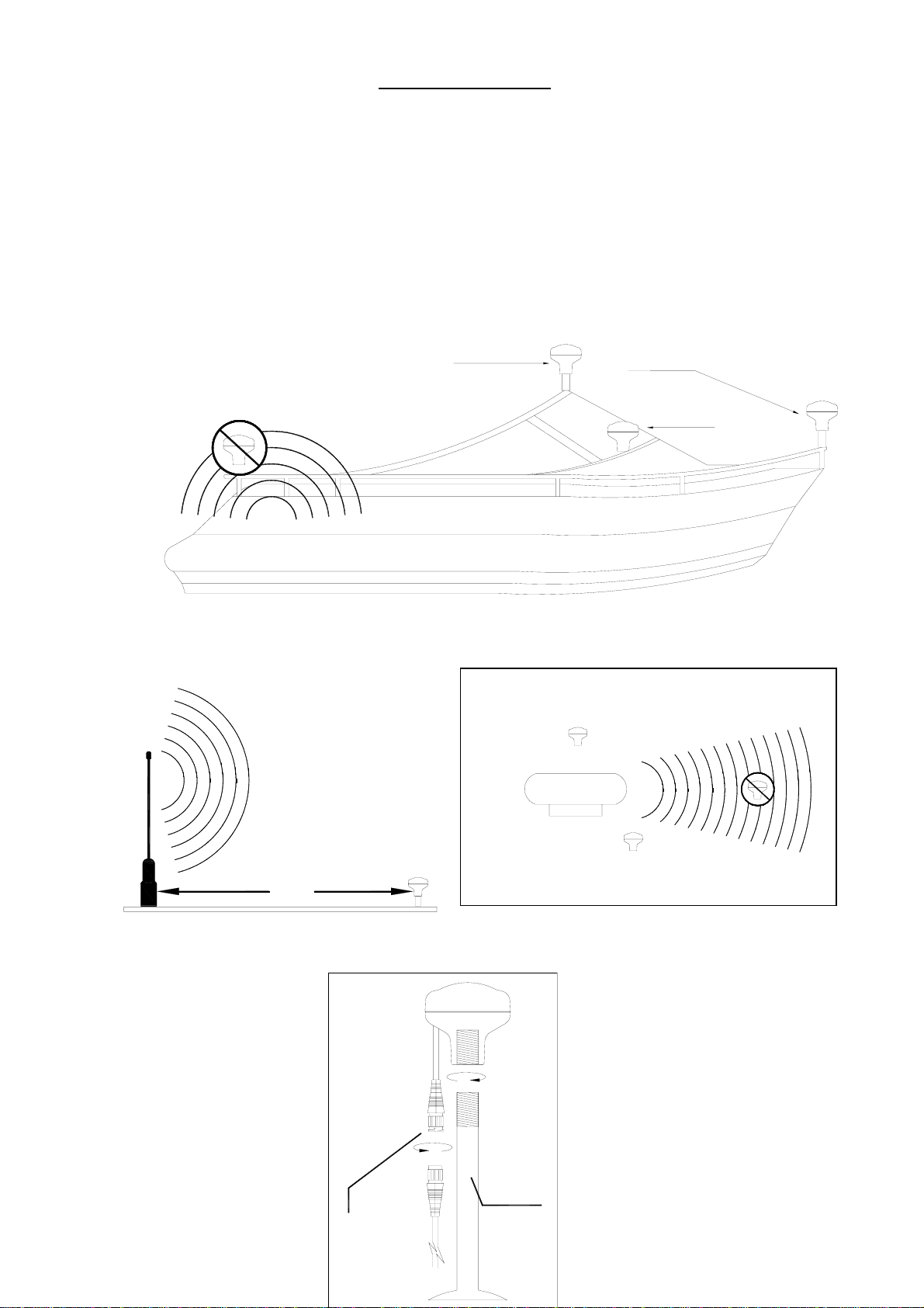
1.3.1 Physical Dimension
Single construction integrated antenna/receiver.
Size: 75.6.0(OD) x 72.7(H) (mm)
2.98"(OD) x 2.86"(H).
Weight: 400g (including 10-meter cable)
1.3.2 Environmental Characteristics
1) Operating temperature: -40oC to +85oC(internal temperature).
2) Storage temperature: -55oC to +100oC.
1.3.3 Electrical Characteristics
1) Input voltage: +8.0 ~ 25.0 VDC.
2) Backup power: 3V Rechargeable Lithium cell battery, up to 460 hours (19 days) discharge.
1.3.4 Performance
1) Tracks up to 12 satellites.
2) Update rate: 1 second.
3) Acquisition time
Reacquisition 0.1 sec., averaged
Hot start 8 sec., averaged
Warm start 38 sec., averaged
Cold start 45 sec., averaged
4) Position accuracy: