ASTRO VA-1842 User manual

HDMI Protocol Analyzer
VA-1842
Terminal Command Instruction Manual
Ver.1.00


HDMI Protocol Analyzer
VA-1842
Terminal Command Instruction Manual
2017.3
Ver.1.00
ASTRODESIGN,Inc.


i
Contents
Contents............................................................................................................................................................................i
Configuration of This Manual...........................................................................................................................................iii
Chapter 1 About Terminal Commands.................................................................................................................................1
1.1. Overview....................................................................................................................................................................1
1.2. Communication Specifications...................................................................................................................................1
1.2.1. LAN .....................................................................................................................................................................1
1.2.2. USB.....................................................................................................................................................................1
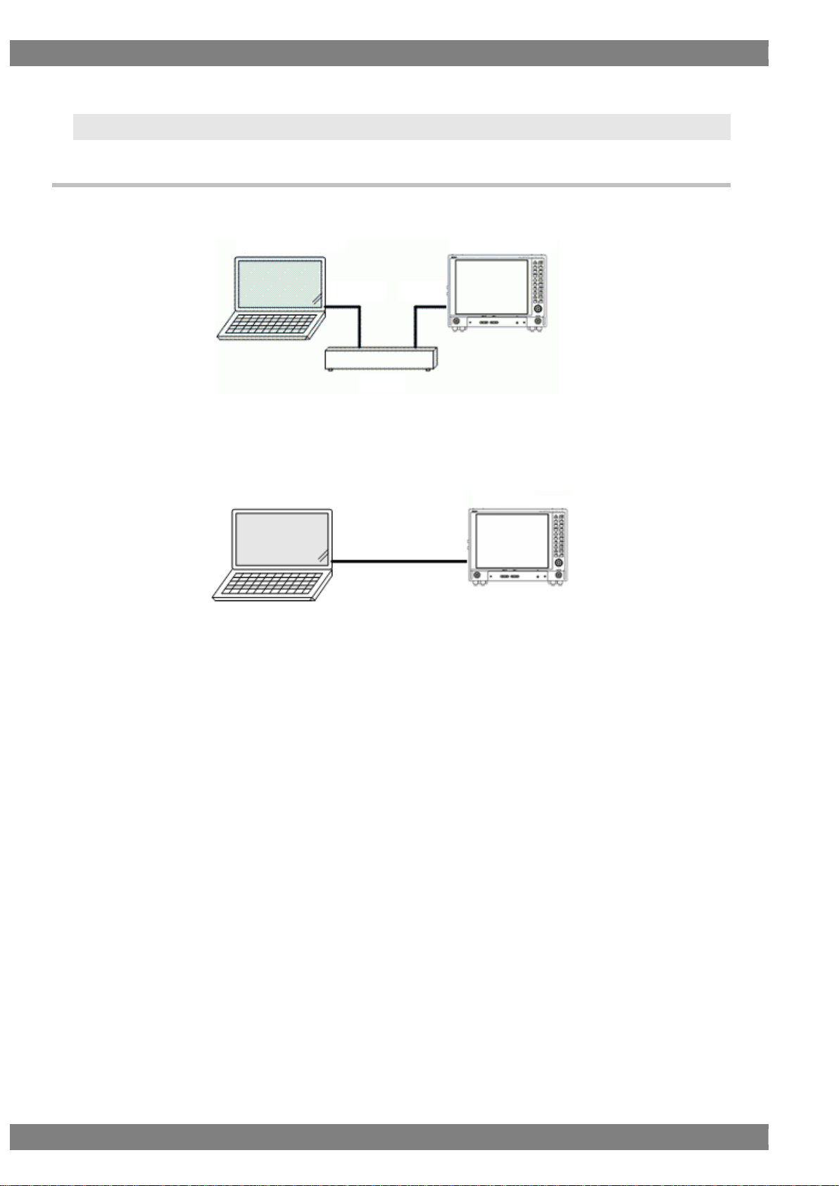
1.3. Connection Configuration..........................................................................................................................................2
1.3.1. LAN .....................................................................................................................................................................2
1.3.2. USB.....................................................................................................................................................................3
1.4. Transmission Control Characters, Data, and Error Commands.................................................................................4
1.4.1. About BCC (Block Check Code)..........................................................................................................................4
1.5. Error Codes...............................................................................................................................................................5
1.6. Command Formats....................................................................................................................................................6
1.6.1. When Transmission of Setting Commands..........................................................................................................6
1.6.2. When Transmission of Acquisition Commands....................................................................................................6
1.7. Communication Protocols..........................................................................................................................................7
1.7.1. Type 1..................................................................................................................................................................7
1.7.2. Type 2..................................................................................................................................................................8
1.7.3. Type 3..................................................................................................................................................................9
1.7.4. Type 4................................................................................................................................................................10
1.7.5. Type 5................................................................................................................................................................11
1.7.6. Type 6................................................................................................................................................................12
1.8. About Timeouts........................................................................................................................................................13
Chapter 2 VA-1842 Setting Commands.............................................................................................................................15
2.1. [0x20 0x40]: Specification of Files to Send/Receive................................................................................................15
2.2. [0x30 0x40]: Acquisition of Folder Names or Filenames in Specified Path ..............................................................17
2.3. [0x20 0x41]: EDID Setting .......................................................................................................................................18
2.4. [0x30 0x41]: EDID Reading.....................................................................................................................................19
2.5. [0x20 0x42]: Config Setting......................................................................................................................................20
2.6. [0x30 0x42]: Config Reading ...................................................................................................................................20
2.7. [0x30 0x43]: USB Flash Connected/Not Connected................................................................................................22
2.8. [0x30 0x44]: VA Version Acquisition.........................................................................................................................23
2.9. [0x20 0x45]: Setup Setting.......................................................................................................................................24
2.10. [0x30 0x45]: Setup Reading ..................................................................................................................................24
2.11. [0x30 0x46]: File Sending ......................................................................................................................................26
2.12. [0x20 0x47]: Config Inc/Dec Setting ......................................................................................................................27
2.13. [0x20 0x48]: Mode Setting.....................................................................................................................................28

ii
2.14. [0x20 0x49]: HDCP Config Setting ........................................................................................................................29
2.15. [0x20 0x4A]: CEC Address Setting........................................................................................................................31
Chapter 3 VA-1842 Measurement Commands..................................................................................................................33
3.1. [0x30 0x50]: Video Timing Reading.........................................................................................................................33
3.2. [0x30 0x51]: Audio Timing Reading.........................................................................................................................35
3.3. [0x30 0x52]: Packet Reading...................................................................................................................................37
3.4. [0x30 0x53]: Channel Status Bit Reading................................................................................................................38
3.5. [0x30 0x54]: HDCP Status Reading.........................................................................................................................39
3.6. [0x30 0x55]: ARC Status Reading ...........................................................................................................................41
3.7. [0x30 0x56]: DDC Line Monitor Reading .................................................................................................................42
3.8. [0x30 0x57]: CEC Line Monitor Reading .................................................................................................................44
3.9. [0x30 0x58]: Video Data Reading............................................................................................................................45
3.10. [0x30 0x59]: SCDC Reading .................................................................................................................................46
Chapter 4 VA-1842 Operation Commands ........................................................................................................................47
4.1. [0x20 0x60]: Hot Plug Pulse Execution....................................................................................................................47
4.2. [0x30 0x60]: Hot Plug Status Reading.....................................................................................................................48
4.3. [0x20 0x61]: Receiver Sense Execution..................................................................................................................49
4.4. [0x20 0x62]: Log Execution .....................................................................................................................................50
4.5. [0x20 0x63] CEC Command Sending......................................................................................................................51
4.6. [0x30 0x64]: DDC OutputAccess............................................................................................................................52
4.7. [0x20 0x65]: Audio Return Channel Execution ........................................................................................................53
4.8. [0x30 0x65]: Audio Return Channel Setting Reading...............................................................................................54
4.9. [0x20 0x66]: Generate Execution ............................................................................................................................55
4.10. [0x30 0x66]: Generate Setting Reading.................................................................................................................57
4.11. [0x20 0x67]: Generate Video Timing Setting..........................................................................................................59
4.12. [0x30 0x67]: Generate Video Timing Setting Reading...........................................................................................60
4.13. [0x20 0x68]: Generate Packet Setting...................................................................................................................61
4.14. [0x30 0x68]: Generate Packet Setting Reading.....................................................................................................62
4.15. [0x20 0x69]: Generate Audio Setting.....................................................................................................................63
4.16. [0x30 0x69]: Generate Audio Setting Reading.......................................................................................................64

Chapter 1 About Terminal Commands
iii
Configuration of This Manual
This is the terminal command instruction manual for the VA-1842 series. It describes the setting procedures,
precautions, and other matters using the configuration shown below. Read this manual carefully to ensure correct
operation and setting.
● Read This First
Chapter 1 About Terminal Commands
Provides an overview of the terminal commands.
● VA-1842 Series Terminal Commands
Chapter 2 VA-1842 Setting Commands
Describes the VA-1842 standard commands.
Chapter 3 VA-1842 Measurement Commands
Describes the VA-1842 measurement commands.
Chapter 4 VA-1842 Operation Commands
Describes the VA-1842 operation commands.
License Notice
HDMI, the HDMI logo and High-Definition Multimedia Interface are trademarks or registered trademarks of HDMI
Licensing LLC.

iv

1
1
1
About Terminal Commands
1.1.Overview
This manual describes the sending and receiving of the commands and data required for operating the HDMI protocol
analyzer (hereinafter referred to as the VA-1842) from an external computer (such as a PC). The commands and data
are sent and received via the serial input/output port LAN or USB peripheral.
1.2.Communication Specifications
1.2.1.LAN
■ Communication conditions
- 10BASE-T, 100BASE-TX
- UDP/IP
■ Connector
RJ-45
1.2.2.USB
■ Communication conditions
- USB2.0
■ Connector
- B connector

2
1.3.Connection Configuration
1.3.1.LAN
■ When connected via a hub
Figure 1.3-1
■ When the PC and VA are connected directly without going through a hub
Figure 1.3-2
With a LAN connection, use a straight cable when connecting through a hub. Use a crossover
cable when connecting the VA and PC directly.
Furthermore, when connecting the PC and VA directly, set the desired IP address, subnet
mask, and default gateway settings rather than automatically acquiring the IP addresses
using the Internet protocol of the PC.
VA-1842
Hub
Host Computer
Straight
Straight
Host Computer
VA-1842
Crossover

Chapter 1 About Terminal Commands
3
1.3.2.USB
Figure 1.3-3
■ Installing the USB driver
(1) When a PC is connected to the VA-1842 for the first time, the system recognizes the VA-1842 and the Add
New Hardware Wizard dialog box appears. Select the [Next] button.
(2) Select [Search for the best driver for your device (Recommended)] as the search method, and select the
[Next] button.
(3) Insert the VA-1842 utility installation CD into the CD drive, select the [CD-ROM drive] or [Specify a location]
check box, select the driver inside the [USB] - [WIN2K] or [USB] - [WIN98] folder in the CD, and click on the
[Next] button.
(4) Check that “ITFUSBDV.sys” is found and then click [Next] to start the installation.
(5) Follow the on-screen instructions.
* When installing the driver in Windows XP, the following dialog box appears asking about verification
by Microsoft. Simply click the [Continue] button.
VA-1842
Host Computer
A-connector
B-connector

4
1.4.Transmission Control Characters, Data, and Error Commands
Code
HEX code
Description
STX
0x02
Start of the text (command) to be transmitted
ETB
0x17
End of the text (data) to be transmitted (However, there is the
following data.)
ETX
0x03
End of the text (command/data) to be transmitted
ENQ
0x05
Request to start terminal mode
EOT
0x04
Request to end terminal mode
ACK
0x06
Positive acknowledgment character
NAK
0x15
Negative acknowledgment character
TRDT
0x10
Data transmission
ESTS
0x11
Transmission of error status
BCC
Any code
Refer to 1.4.1 About BCC (Block Check Code).
1.4.1.About BCC (Block Check Code)
BCC is used to check the validity of a command.
When a command is sent, the sum of setting command CMD1 to ETX (ETB) in the command to be sent is calculated,
and 1 byte is sent immediately after ETX (ETB). At this time, the VA-1842 checks the data, and if the data and BCC do
not match, BCC_ERR is returned from the VA-1842.
When a command is received, the sum of CMD1 to ETX (ETB) of the received command is calculated, and the validity
of the data is checked using BCC of the received command and the calculated BCC.
■ Example of creating BCC
STX
0x02
CMD1
0x20
CMD2
0x40
Target of BCC creation
PARM
0x01
ETX
0x03
BCC
0x64 checksum

Chapter 1 About Terminal Commands
5
1.5.Error Codes
Code
HEX
code
Description
PARM_SIZE_ERR
0x01
The parameter size is incorrect.
Alternatively, the data length and amount of data sent do not match
(only when type 5 or 6).
PARM_DATA_ERR
0x02
The parameter value is incorrect.
CMD_EXEC_ERR
0x03
Execution of the processing instructed by the command failed.
BAD_CMD_ERR
0x04
The command is incorrect. (CMD1, 2)
BCC_ERR
0x05
The checksum is not match.
CEC_SEND_HAND
0x10
Error handling was returned for the CEC send command.
CEC_SEND_BUSSF
0x11
The CEC command cannot be sent because BUSS is not free.
CEC_SEND_ARB
0x12
An arbitration error occurred for the CEC send command. (In the
Start or Initiator part)
CEC_SEND_ACK
0x13
ACK was not returned for the CEC send command.
CEC_SEND_IMP
0x14
An arbitration error occurred for the CEC send command. (In other
than the Start or Initiator part)

6
1.6.Command Formats
1.6.1.When Transmission of Setting Commands
Transmission of commands from a computer to the VA-1842 (PC VA)
STX
CMD1
CMD2
ETX
BCC
or
STX
CMD1
CMD2
PARM
ETX
BCC
Value returned from the VA to the computer after command transmission (PC VA)
ACK
or
STX
ESTS
ErrorCode
ETX
BCC
If data is required, it is sent as follows only when the command is sent and the return value isACK (PC VA)
STX
TRDT
PARM
ETB
BCC
or
STX
TRDT
PARM
ETX
BCC
Value returned from the VA to the computer after data transmission (PC VA)
ACK
or
STX
ESTS
ErrorCode
ETX
BCC
1.6.2.When Transmission of Acquisition Commands
Transmission of commands from a computer to the VA-1842 (PC VA)
STX
CMD1
CMD2
ETX
BCC
or
STX
CMD1
CMD2
PARM
ETX
BCC
Value returned from the VA to the computer after command transmission (PC VA)
ACK
or
STX
ESTS
ErrorCode
ETX
BCC
WhenACK is returned, the data is received as follows (PC VA)
STX
TRDT
PARM
ETB
BCC
or
STX
TRDT
PARM
ETX
BCC

Chapter 1 About Terminal Commands
7
1.7.Communication Protocols
1.7.1.Type 1
This sequence is used when terminal commands are started.
Figure Type 1
Sequence
no.
Command
Send/receive
direction
1
ENQ
Send
2
ACK
Receive
1
PC
VA 2

8
1.7.2.Type 2
This sequence is used when sending commands with the only CMD (command) and PARM (parameter) parts
(if necessary).
Figure Type 2
Sequence
no.
Command
Send/receive
direction
1
STX
CMD*
(PARM)
ETX
BCC
Send
2a
(successful)
ACK
Receive
2b (failure)
STX
ESTS
ErrorCode
ETX
BCC
Receive
* It is assumed that the following two codes are contained in the CMD (command) part.
CMD1
CMD2
PC
VA
1
2a or 2b

Chapter 1 About Terminal Commands
9
1.7.3.Type 3
This sequence is used for receiving the VA data.
Figure Type 3
Sequence
no.
Command
Send/receive
direction
1
STX
CMD*1
(PARM)
ETX
BCC
Send
2a
(successful)
ACK
Receive
2b (failure)
STX
ESTS
ErrorCode
ETX
BCC
Receive
3
STX
TRDT
PARM
ETX
BCC
Receive
4
ACK
Send
*1 It is assumed that the following two codes are contained in the CMD (command) part.
CMD1
CMD2
*2 If a failure occurs in 2b, the sequence flow is ended at that point.
PC
VA
1
2a or 2b 3
4

10
1.7.4.Type 4
This sequence is used for sending the VA data.
Figure Type 4
Sequence
no.
Command
Send/receive
direction
1
STX
CMD*1
(PARM)
ETX
BCC
Send
2a
(successful)
ACK
Receive
2b (failure)
STX
ESTS
ErrorCode
ETX
BCC
Receive
3
STX
TRDT
PARM
ETX
BCC
Send
2a
(successful)
ACK
Receive
2b (failure)
STX
ESTS
ErrorCode
ETX
BCC
Receive
*1 It is assumed that the following two codes are contained in the CMD (command) part.
CMD1
CMD2
*2 If a failure occurs in 2b, the sequence flow is ended at that point.
PC
VA
1
2a or 2b
3
2a or 2b

Chapter 1 About Terminal Commands
11
1.7.5.Type 5
This sequence is used for receiving the VA data. PARM (parameter) must be received the desired number of
times.
Figure Type 5
Sequence
no.
Command
Send/receive
direction
1
STX
CMD*1
(PARM)
ETX
BCC
Send
2a
(successful)
ACK
Receive
2b (failure)
STX
ESTS
ErrorCode
ETX
BCC
Receive
3
STX
TRDT
PARM
ETB
BCC
Receive
4
ACK
Send
3 and 4 repeated the desired number of times
5
STX
TRDT
PARM
ETX
BCC
Receive
4
ACK
Send
*1 It is assumed that the following two codes are contained in the CMD (command) part.
CMD1
CMD2
*2 If a failure occurs in 2b, the sequence flow is ended at that point.
*3 The configuration of the data in PARM of sequence flow no. 3 or 5 is shown below.
Data Length1
Data Length2
Packet No.
(Data)
…
(Data)
Item
Description
Data Length
Stores the number of bytes of PARM in the corresponding sequence flow. (3 +
number of data bytes sent)
Packet No.
Stores how many times data sent by the corresponding sequence flow. (Number of
times sent –1)
Data
Stores the data to be received.
PC
VA
1
2a or 2b 3
4
………
5
4

12
1.7.6.Type 6
This sequence is used for sending the VA data. PARM (parameter) must be sent the desired number of times.
Figure Type 6
Sequence
no.
Command
Send/receive
direction
1
STX
CMD*1
(PARM)
ETX
BCC
Send
2a
(successful)
ACK
Receive
2b (failure)
STX
ESTS
ErrorCode
ETX
BCC
Receive
3
STX
TRDT
PARM
ETB
BCC
Send
2a
(successful)
ACK
Receive
2b (failure)
STX
ESTS
ErrorCode
ETX
BCC
Receive
3 and 2a or 2b repeated the desired number of times
4
STX
TRDT
PARM
ETX
BCC
Send
2a
(successful)
ACK
Receive
2b (failure)
STX
ESTS
ErrorCode
ETX
BCC
Receive
*1 It is assumed that the following two codes are contained in the CMD (command) part.
CMD1
CMD2
*2 If a failure occurs in 2b, the sequence flow is ended at that point.
*3 The configuration of the data in PARM of sequence flow no. 3 or 5 is shown below.
Data Length1
Data Length2
Packet No.
(Data)
…
(Data)
Item
Description
Data Length
Sets the number of bytes of PARM in the corresponding sequence flow. (3 +
number of data bytes sent)
Packet No.
Sets how many times data sent by the corresponding sequence flow. (Number
of times sent –1)
Data
Sets the data to be sent.
This shows an example of the commands in 2.3 [0x20 0x41]: EDID Setting.
■ Data in two blocks (256 bytes) is set in increments of 128 bytes.
PC
VA
1
2a or 2b
………
3
2a or 2b
4
2a or 2b
Other manuals for VA-1842
1
Table of contents
Other ASTRO Measuring Instrument manuals
Popular Measuring Instrument manuals by other brands

Test Products International
Test Products International Vib Meter 9085 user guide

Secure
Secure TRACKSO ELITE 103-2 installation guide

MMG
MMG TQI-021/1 user manual

VOLTCRAFT
VOLTCRAFT ENERGY MONITOR 3000 user manual

Johnson Level & Tool
Johnson Level & Tool 40-6645 instruction manual

LaserLine
LaserLine LaserRange-Master i5 manual