ASTRODEVICE TC 900 User manual

Tilt Corrector
TC 900
User Manual
rev. 2022-11-09
STRODEVICE

Package contents:
1. Tilt Corrector
2. M4x8 screws (6 pcs)
3. M4x4 headless screws (4 pcs)
4. M2.5x10 screws with washers (4 pcs)
1
4
6
- 3 -
23
4

First read the en•re manual and make sure that everything is clear to you.
Only then start working with TIlt Corrector.
If you have any ques•ons, please contact Astrodevice.
Introduction
Tilt Corrector is a device for adjusting tilt angle of the camera in the optical path
of the telescope. It works with any telescope and ZWO ASI 2400 MC Pro, ASI 2600
MM/MC Pro and ASI 6200 MM/MC Pro cameras. The tilt adjustment screws can
be accessed from the back of the camera, so that the camera does not need to be
removed from the set during adjustment, and the entire adjustment procedure
can be carried out with a live preview of the result. In addition to such continuous
operation, a special procedure, described further in this manual, makes it possible
to transfer the determined settings to the camera’s original black tilt plate or to
the Astrodevice •lter drawer.
Usage
The device is designed to work in conditions of 0-40 degrees Celsius (32°F - 104°F).
High temperatures
Although PET-G is relatively robust, too high a temperature can lead to
deformations. If you don’t even notice them, the micro structural changes can
cause the device to become uncalibrated. Therefore, do not store or use the
Corrector at high temperatures. Adopt the rule of thumb that if it’s too hot for
you, so is for the device.
Low temperatures
Our accessories have been successfully tested in temperatures as low as -20
degrees Celsius (-4°F). Although the use of the device in freezing temperatures
is technically possible, there is a risk associated with the phenomenon of ice
- 4 -

condensation. If water freezes in the crevices of the structure, ice can damage the
accessory and lead to its destruction. Therefore, if you intend to use the Correctorin
freezing weather at your own risk, make sure that the environment is dry.
Under all conditions, work with the device should be personally supervised. Before
use, make sure that the accessories and their threads are not damaged and that
they are securely mounted. Never use a defective device.
- 5 -
Technology, design and elements
Tilt Corrector was made with 3D printing technology using carbon !ber reinforced
PET-G plastic. Re!nement with this material signi!cantly strengthens the
construction and on the outside it manifests itself with a characteristic, slightly
rough texture.
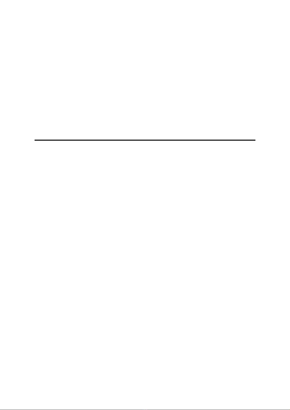
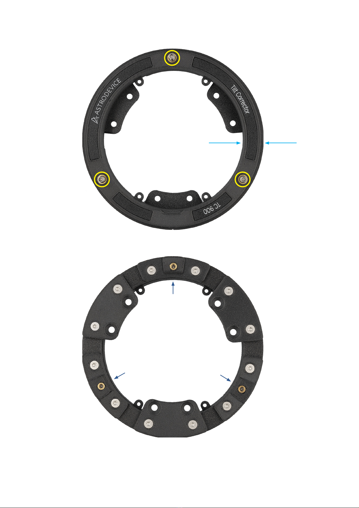
The device consists of two coaxial rings (!g. 1 - R1, R2) connected by three
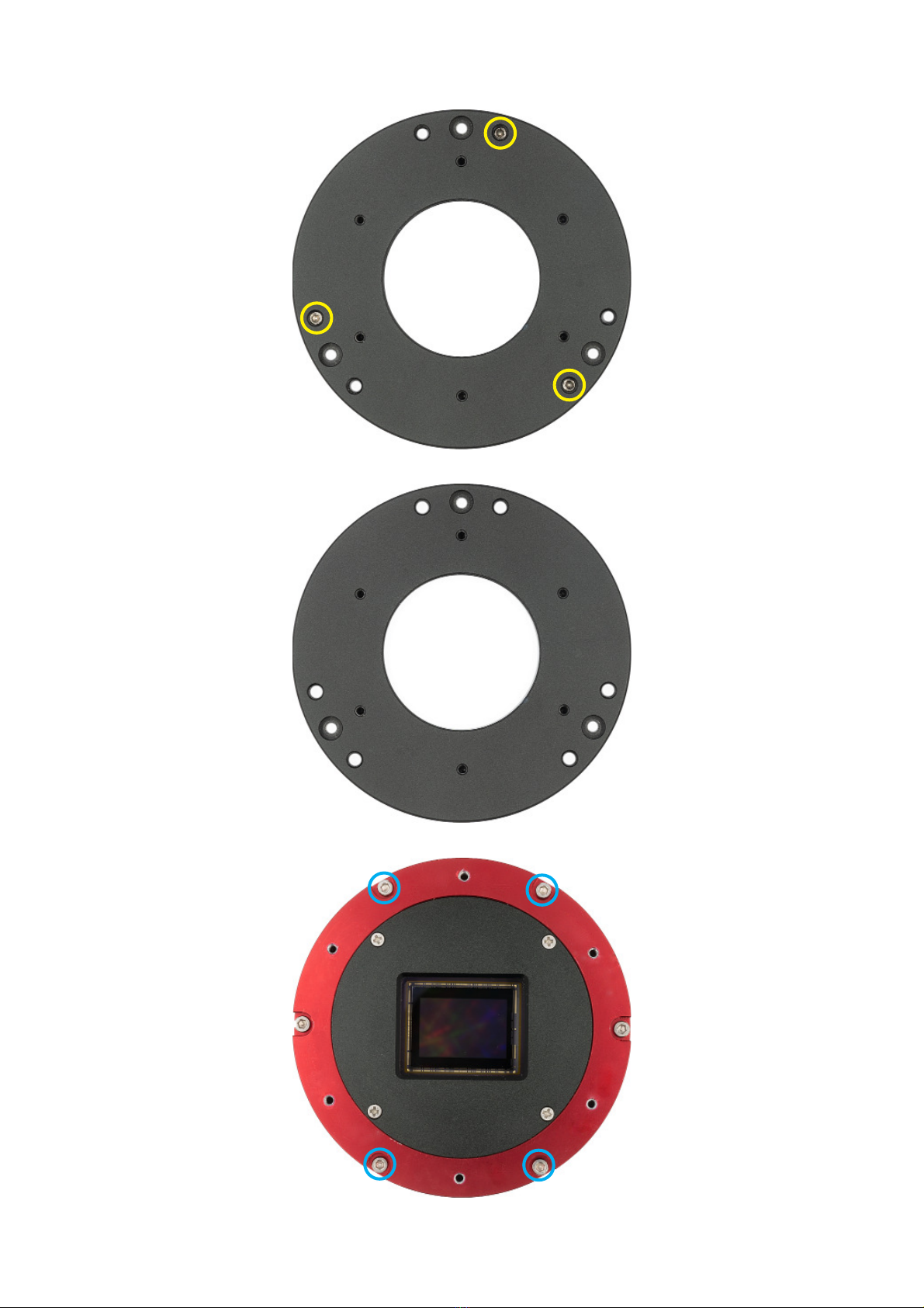
adjustment screws (S1, S2, S3). The narrower ring, R1, is mounted to the camera
housing through mounting holes H1 - H4. Rotation of screws S1, S2 and S3 pushes
back the wider ring R2, and thus changes the camera’s tilt angle. Clockwise rotation
of the screws moves the planes away from each other, while counterclockwise
rotation brings them closer together. The position where the planes of the rings
touch each other, no adjustment has yet been made, this initial position, will be
referred to as the zero position.
The back of the Tilt Corrector shows 2 groups of components, each of which
consists of three elements arranged around the perimeter every 120 degrees.
In the !rst group there are three bridges B1, B2 and B3 on the center of which there
are adjustment screws BS1, BS2, BS3. The bridges are permanently mounted with
side construction screws marked with a red xmarker. Please do not nor unscrew
these mounting screws, as this may lead to irreparable damage of the drawer.
The second group contains three tabs T1, T2 and T3 for mounting the original tilt

- 6 -
plate. Each tab is bolted with two removable TS screws. In place of the tabs, other
brackets can also be screwed on, for mounting the Astrodevice FD 900 M87 •lter
drawer.
As you will no•ce, this manual repeatedly points out that this work should not
use force. You are dealing with fine threads and strong yet small parts. Everything
should work smoothly and if there is any resistance, it should be even and easy
to overcome. A no•ceable, slightly greater resistance to the rota•on of the screws
occurs only when adjus•ng the •lt - this is appropriate and desirable.
Do not •ghten the screws forcibly, do not •ghten them brutally, because then you
create stresses in the material, which can lead to distor•on of the image or damage
to the structure of objects.

fig. 1
X
X
XX
X
- 7 -
X
R1 R2
S1
S2
S3
]
]
]
]
]
]
T1 T2
T3
B1
B2
B3
H1 H2
H3
H4
BS1
BS2
BS3
TS
TS
TS
TS
TS TS

Installation
The installation procedure follows two successive steps:
1. mounting the Tilt Corrector on the camera
2. mounting to the camera with the Tilt Corrector:
A. original black tilt plate
or
B. Astrodevice !lter drawer FD 900 M87
After completing steps 1 and 2, the camera can be mounted on a telescope.
***
STEP 1
Mounting the Tilt Corrector on the camera
Before you proceed, prepare a small ziplock bag into which you can hide the
screws you will be removing. This will make your work much more e"cient.
1. Place the camera on a flat table with the tilt plate facing up.
See !g. 2.
2. Remove the three screws holding the tilt plate.
Use 2 mm hex wrench, like the one provided with camera. See !g. 3. Be careful,
as tiny screws may fall. Secure them after removal so that they are not lost.
3. Remove the tilt plate.
See !g. 4.
- 8 -

fig. 2
fig. 3
fig. 4
- 9 -

4. Remove tilt adjustment bolts.
Remove three M4x4 headless screws from the tilt plate. They are originally
used for tilt adjustment. They are very small. Secure them in a safe place so
they don’t get lost. See •g. 5.
After this step, the original black tilt plate should be free of any screws. See
•g. 6.
5. Prepare the camera housing for Tilt Corrector mounting.
The Tilt Corrector is mounted to the camera using the four screws originally
tightening the top of its housing. In total, on the sensor side, the camera
housing is bolted with six screws, but only four will be used to mount the
Tilt Corrector. This eliminates the risk of disassembling the housing, as the
two screws remain in place at all times during installation. This step involves
temporary removing four of the six screws of the camera housing, and then
screwing new screws in through the holes in the Tilt Corrector ring.
Using a 2 mm hex wrench, remove the four M2.5x8 screws marked in •g. 7 in
blue. Note that these are the screws located above and below the longer edge
of the sensor. After removing the screws, your camera should look like the one
in •g. 8.
As in previous cases, also hide these screws in a safe place, preferably in a
ziplock bag that you have prepared for this purpose.
6. Prepare Tilt Corrector
Tilt Corrector is supplied with the rings as close to each other as possible. In
order not to cause stress during installation, you should start by loosening the
contact between rings, that is, moving them away from each other to a safe
distance of about 1,5 mm. To do this, use a 2 mm hex wrench to turn each
of the adjustment screws S1, S2 and S3 two full turns clockwise. Please also
unscrew the three tabs T1, T2 and T3 located on the back of the Tilt Corrector
(see •g. 9).
- 10 -

- 11 -
fig. 5
fig. 6
fig. 7
- 11 -

fig. 8
fig. 9
- 12 -

7. Mount Tilt Corrector on the camera
Place the Tilt Corrector in front of you in the position as shown in •g. 10.
Note the vertical line visible in front of you and the notch located on the top
plane of the Tilt Corrector. Both of these features are marked on •g. 10 in green.
The line serves to give you an easy indication of how the Tilt Corrector should
be positioned relative to the camera during installation. The Tilt Corrector
should be put on the camera in such a way that the line is on the same side as
the black dot on the camera housing. Then, when the Tilt Corrector is slid onto
the camera, the notch will overlap the black dot.
Now turn the Tilt Corrector upside down, in such a way that the characteristic
line is still in front of you (•g. 11).
Grasp the Tilt Corrector with both hands and slide it on top of the camera
(•g. 12). Look from the top and •ne-tune the positioning so that the Tilt
Corrector’s mounting pro•les go into the notches in the housing from which
you previously removed the screws (•g. 13). The •t is tight, but tailored. Work
gently and do not apply too much force. Corector’s holed mounting pro•les
must pop all the way into place - then you will be left with about 3 mm of free
space above them (•g .14).
Screw the Tilt Corrector to the camera using the four prepared screws with
washers (•g. 15). Do not use force for installation. Be careful not to strip the
thread. Do everything gently. Tighten the screws to the •rst resistance, but
not too tight. The screw in the thread should turn freely. If you feel too much
unnatural resistance, give up, remove the screw, take o• the Tilt Corrector and
try to screw in the screw alone making sure that it screws in lightly, correctly
and there is no risk of stripping the thread.
- 13 -

fig. 10
fig. 11
- 14 -

fig. 12
fig. 13
- 15 -

fig. 14
fig. 15
- 3 mm
- 16 -

STEP 2A
Installation of the original black tilt plate in the Tilt Corrector
As already mentioned, the Tilt Corrector can work with both the camera’s original
black tilt plate and the Astrodevice FD 900 M87 •lter drawer. Since the camera with
the plate is the most basic set that can work with any telescope, this con•guration
will be discussed •rst. If you have a Celestron RASA 8 telescope and want to use
the Astrodevice •lter drawer, after reading this section, proceed to step 2B.
Place the original black tilt plate on the camera with the Tilt Corrector installed
(•g. 16). Make sure that the screw holes in the tilt plate and in the Tilt Corrector
are aligned with each other as shown (•g. 16, yellow lines). A good indicator of
whether the tilt plate is correctly positioned is that the mounting holes of the tilt
plate and the camera underneath overlap (•g 16, yellow circles).
Screw the T1, T2, T3 tabs to the Tilt Corrector, (•g. 17, green circles). Then tighten
the tilt plate with the supplied M4x8 screws using a 2.5 mm hex wrench (•g. 17,
red circles).
After screwing the tilt plate, return to the initial position by turning the screws S1,
S2 and S3 back, which is the opposite direction from that shown in •g. 9. When
returning to the zero position, do not use force. When you feel the •rst resistance,
do not continue turning the screw. You should bring the rings towards each other,
but not pull them further, causing tension. Work with sensitivity and gentleness.
Now your camera is ready to go. However, before you start screwing the accessory
to the M42 thread on the front of the black tilt plate, note that over the length of
the •rst 5 mm, the •rst mounted accessory must not be more than 70 mm in
diameter (see •g. 18). For this reason, in most cases you cannot mount most •lter
drawers or a •lter wheel to the tilt plate directly. If you would like to mount such
an accessory, you must •rst screw on a spacer, such as a 6-millimeter length (see
•g. 19 as an example). Note, that depending on the size of the •lter and the focal
length of the telescope, moving the •lter away from the sensor may result in
increased vignetting.
- 17 -

fig. 16
fig. 17
- 18 -

fig. 18
d = max 70 mm
h > 5 mm
fig. 19
- 19 -

STEP 2B
Installation of the FD 900 M87 •lter drawer in the Tilt Corrector
This step is for those with a Celestron RASA 8 telescope and an Astrodevice FD 900
M87 •lter drawer.
•
Due to the geometry of the Tilt Corrector, working with the Astrodevice FD 900
M87 drawer is somewhat limited. When you use the Tilt Corrector, it is not possible
to slide the •lter sliders in and out. Therefore, in such a case, the sense of using
the Astrodevice drawer can be twofold: •rst, you can use the Tilt Corrector to
set the correct tilt in the drawer, and then remove the Tilt Corrector and use the
drawer normally, with the correct tilt already established. You will learn about how
to do this later in the manual. If, however, you care about continuous operation,
that is, working with the Tilt Corrector on all the time, then you may work with the
drawer as a •lter adapter, making use of the front thread for 2” •lters.
The FD 900 M98 •lter drawer is equipped with •ve M2.5 screws for attaching it to
the camera. Turn the drawer’s large M87 nut so that the screw heads are exposed
from the top of the drawer. Then slide the screws out of the drawer by pushing
them out from the bottom.
Next, make sure that the screws used to adjust the tilt are completely retracted
inside the drawer and do not protrude above the bottom surface.
After these two operations, the bottom of the drawer should look like this, as
shown in •g. 20. The green circles mark the empty spaces left after removing the
mounting screws. The red circles mark the tilt adjustment screws, which are made
sure that they do not protrude above the mounting surface.
In this part of the work, the user’s manual of the FD 900 M87 •lter drawer may help
you. It describes the construction and drawer in detail. The manual is available at:
https://astrodevice.com/user-manuals
Now, remove the slider (if there is one) from the •lter drawer and put the drawer on
the camera with the Tilt Corrector in place (•g. 21). Position the bottom U-shaped
part of the drawer against the Tilt Corrector in the orientation as schematically
shown in •g. 22.
- 20 -

fig. 20
fig. 21
- 21 -
Table of contents
Popular Accessories manuals by other brands

Vega
Vega VEGASON 61 Quick setup guide

Ritron
Ritron 7 Series owner's manual

Dorner
Dorner 6200 Series Installation, maintenance & parts manual

Philips
Philips AEA1000/00 quick start guide

ABB
ABB CSU-2LV Installation and maintenance guide

Rockwell Automation
Rockwell Automation Allen-Bradley 42AF-P2MAB1-D4 user manual