Avalon M-zero LHQ User manual

INSTRUCTION MANUAL
Version 1.0.1 July 2020
All the pictures and contents here included are property of AVALON INSTRUMENTS. The contents cannot be
reproduced published copied or transmitted in any way including the internet without the written permission of
AVALON INSTRUMENTS.

SAFETY STANDARDS AND WARNINGS
Read the manual carefully before installing and using the mount.
To make the document easier to read in the field we recommend that you to copy
all documentation files from the supplied USB drive to a smartphone or even
better to a computer or tablet.
Use the power cable supplied with the mount or else a 15V- 3A stabilized power
supply as suggested in the manual.
Make sure that the power cable is connected correctly and securely to the power
socket.
Do not bend pull or press the cable as this may damage it.
For any assistance or repairs please contact only the manufacturer.
Be sure to remove the power supply at the end of an observing or imaging session
or before performing cleaning or maintenance. When removing from a power
outlet pull on the plug not the cable.
This mount is intended for use exclusively by adults. Do not allow it to be used by
children under 12 or by people with impaired mental faculties.
Operate the mount only as indicated in the manual.
Modifying or altering the characteristics of the mount in any way will void the
manufacturer’s limited warranty.
Never modify the tension of the belts (governed by a dedicated screw). These are set
in the factory and any unauthorized change will void the manufacturer’s limited
warranty.
After using the mount avoid storing it in areas exposed to sunlight or in wet places.
IMPORTANT NOTE: DO NOT USE ANY KIND OF LUBRICANT SPRY LIQUID OR
OIL ON THE BELT DRIVE SYSTEM!!!
Any use of lubricants will void the manufacturer’s limited warranty.
© All Rights reserved 2

Table of Contents
Summary.................................................................................................................................... 3
Technical Specifications.............................................................................................................4
Foreword.................................................................................................................................... 5
Package Contents........................................................................................................................5
1. Set the M-zero to ocal Conditions.....................................................................................6
1.1 Tripod Mounting...........................................................................................................6
1.2 Installing the Mount on the Tripod................................................................................7
1.3 Motor Cable Connections..............................................................................................7
1.4 Altitude Range Setting..................................................................................................8
1.5 Optical Tube Mounting...............................................................................................11
1.6 Choosing the Telescope...............................................................................................11
2. Telescope Balancing Operations........................................................................................16
2.1 Declination Axis Balancing.........................................................................................16
2.2 Right Ascension Axis Balancing:................................................................................17
3. M-zero Alignment in Equatorial Mode..............................................................................19
3.1 atitude Regulation.....................................................................................................19
3.2 Azimuth adjustment....................................................................................................20
3.3 Precise Polar Alignment..............................................................................................20
3.3.1 Polar Kit Installation.............................................................................................20
3.3.2. Polar alignment with a Skywatcher Polarscope....................................................21
3.4 External Programs for Polar Position Finding..........................................................23
5. StarGO Installation and Use – Quick User Guides............................................................29
APPENDIX A..........................................................................................................................30
© All Rights reserved 3

Technical Specifications
Type Equatorial Single-Arm mount with Fast-Reverse technology
Weight 10,1 kg (22,2 lbs.)
oad Capacity For photographic use 8 kg (17.6 lbs.) – For visual use 10 kg
(22,05 lbs.)
Transmission Four-step reducer via pulley-toothed belt system on ball
bearings, with no play in the axis
Construction
material
Anodized aluminum, machined from single blocks with high
precision CNC machines
Motion system Pulleys made with special glass fiber polymer and high
precision toothed belts
Polar finder Celestron standard, others optional
Goto system StarGO GOTO System
Counterweight bar W= 16 mm (0.63 inch) / = 85 mm (3.34 inches)
Counterweight 0.5 kg (1.1 lbs.)
Mounting Saddle Vixen style
Warranty 2 years from the purchase date, extended to 5 years for the
transmission system
© All Rights reserved 4

Foreword
This manual describes the mounting, operation and correct setup of the M-zero HQ, including
the proper installation of a suitable optical tube.
Please read this manual carefully to guarantee that you can use the M-zero HQ mount in
complete safety and with the maximum satisfaction.
The instructions related to the StarGO control system and related software are described in
separate Instruction Manuals:
Avalon Instruments - StarGO Control System
The instructions for using the M-zero HQ with third party software are contained in the
following Instruction Manual:
Avalon Instruments – Avalon StarGO: Third Party Software Use
Both the above manuals are included in the flash drive supplied with the mount.
The images published in the manual refer to the early versions of the mount and therefore small
differences could exist between these illustrations and your own mount. Furthermore, the
design and the configuration of the mount can be subject to modifications without prior notice,
based on design decisions leading to continuous improvements and on the suggestions of mount
owners.
© All Rights reserved 5

1. Packing Content
Open the box and take out all the contents. Remove all the components from the small
cardboard box and from the mount bag side pocket, and place them on a clean, flat surface.
Component List
Aluminum tripod with StarGO control box
Motor’s connecting cable
Mount Head
Mount Head and accessory transport bag
Tripod transport bag.
Counterweight rod
StarGO Keypad
0.5 kg Counterweight
Polar scope with support
Power cable
Warranty & Testing Certificates
Declaration of Conformity
Allen wrench
USB flash drive with manuals and software
Ra/Dec motor cables
© All Rights reserved 6

2 Mount Description
Strong, light and smart, with a total weight of 5.5 kg (12 lb), this very special version, being one
of the few equatorial mount suitable for very low latitude areas till 0° in the market, it is the
perfect instrument for the travelling astronomy, suitable for deep-sky imaging in the capacity
range up to 10 kg (22 lb).
The following drawing show the M-zero mount dimensional characteristics. Dimensions are in
mm.
The M-zero HQ design was developed on the basis of the M-zero standard version, making
use of the same technical concepts:
•Fast Reverse technology
•Computer aided design (CAD)
•High quality manufacturing with digital control 5 axes CNC machines (CNC + CAM)
•Absolute quality materials: Anodized aluminium from milled mono-bloc, stainless steel
components and screws, brass components, techno-polymers
© All Rights reserved 7

The M-zero HQ motion transmission technology is based on pulley-tooth belt without play,
while its peculiar geometry makes easy the imaging at the meridian crossing regardless the
typical problem affecting the classic German Equatorial Mounts, for both the risk of touching
the tripod and the need of waiting for the object cross the meridian.
Moreover, considering that at the meridian the sky is less subject to light pollution and to
atmospheric turbulence, the M-zero HQ is the ideal tool to shoot deep-sky objects in their best
conditions, close to the meridian, especially when the time is short and the sky is not so dark
and clear.
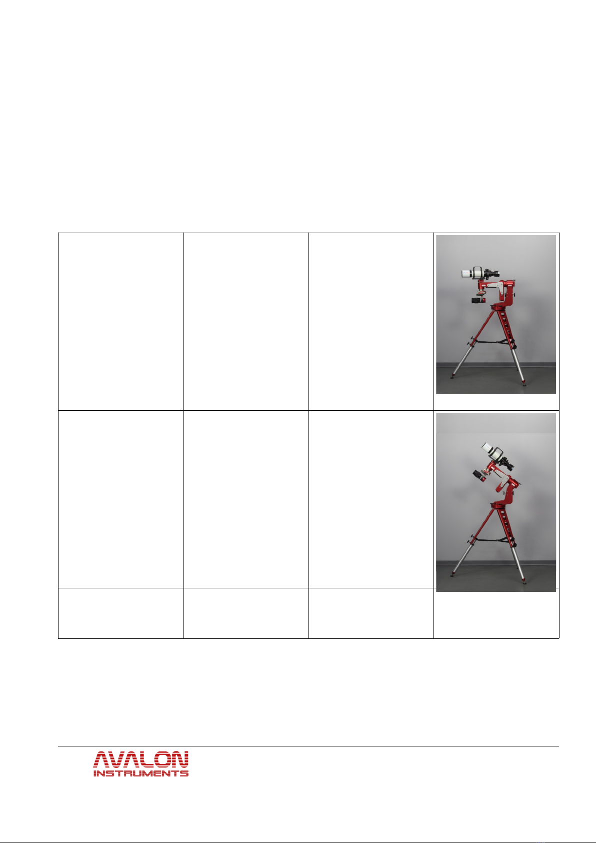
The M-zero HQ is mainly designed for astro-imaging with medium-short length tubes (such as
SC-Maksutov, RC up to 6-8″ aperture and 10 kg (22 lb) weight, according to the tube length). It
is possible to use the M-zero HQ even with refractors (400-500 mm), with a piggyback or
parallel guidescope that can act also as an active counterweight.
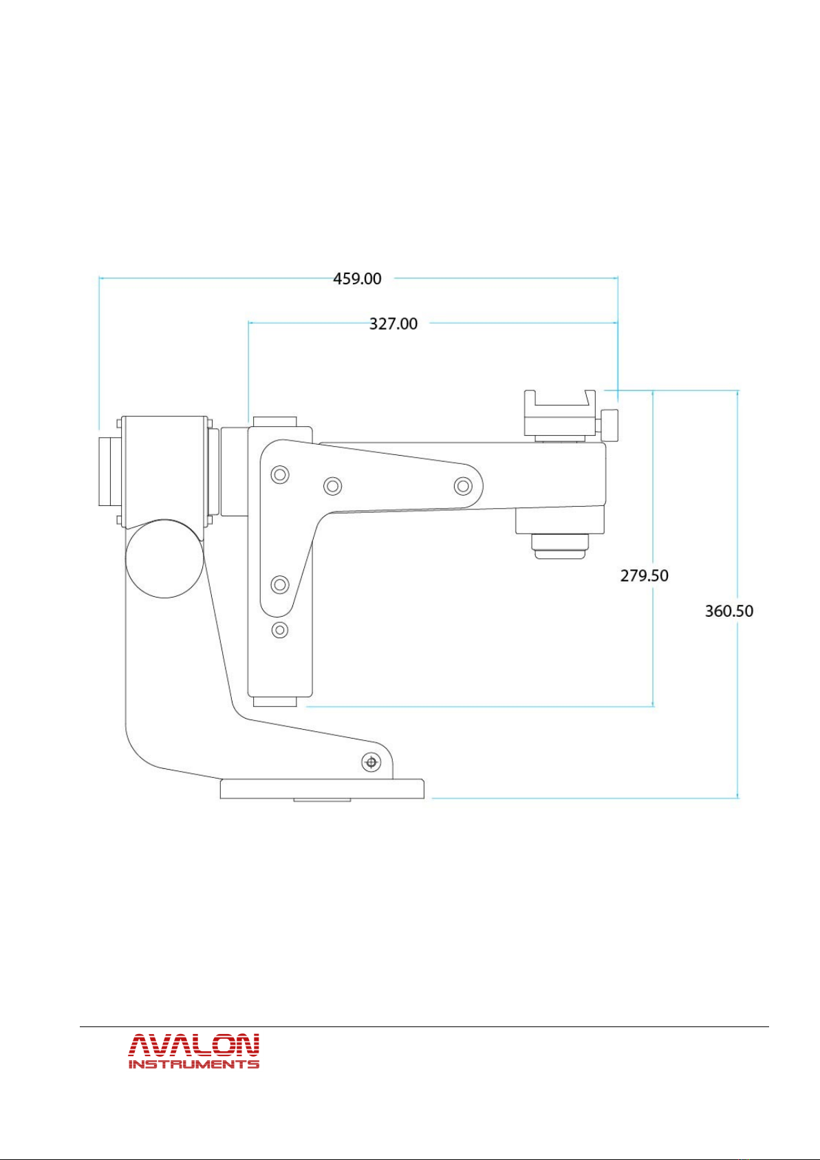
The larger overhang of the single arm system will allow a greater pointing angle compared to
the classic German Equatorial Mounts.
Another M-zero HQ basic advantage is that it doesn't need heavy counterweights, nor the long
bar. Its declination axis can be quickly balanced like in an equatorial mount, while, for the RA
axis, it is possible to fix the arm on six possible positions and to make the fine balance using a
very small counterweight.
The use of pulleys and toothed belts has allowed to obtain several advantages: a really steady
motion without play (no backlash) and sudden peaks, factors of paramount relevance for long
guided exposures and during high magnification visual observations. These features are of
particular relevance especially for the declination axis motor that can now quickly reverse the
motion without breaks to recover the plays: from here the mount name FAST REVERSE. The
toothed belts used in the M-zero HQ have the structure made of special material with steel
strands to avoid any deformation, elongation and stress, much better than those used in the
automotive engine distribution system (which are generally made of rubber with nylon strands).
Considering that the service time for the automotive toothed belts is around 100.000 km
(60.000 miles), assuming a medium regime of 2.000 rpm and thermal stress from 0 to 90°C (30
to 195 F) in a few minutes, we can think that the life cycle of the M-zero HQ toothed belts
will be extremely long! It is important to underline that in the gear-worm systems the motion
transmission has only one tangent point of contact, any errors on each of the two components
will, sooner or later, result into a tracking errors. On the contrary, in the pulley-toothed belt
system, no direct contact occurs between the pulley and the motion is transmitted by the belt
engaging from 50% to 90% of the girth surface. Consequently any error, eventually present, is
averaged among the cogs, moreover soft, greatly reducing the tracking error.
No wearing effects since no relevant frictions occur. In fact, all the pulleys and the axes rotate
on roller bearings, 13 for the RA axis and 13 for the DEC axis that allow to reduce the total
friction almost to zero.
© All Rights reserved 8

Another significant advantage of very low frictions is that the risks of motor slipping during
GOTO operation is virtually null. On the contrary, it is well known the difficulty to regulate the
coupling between gear and worm in the conventional mounts. If the coupling is tight the motors
can stuck with consequent loss of the position, if the coupling is too loose the plays increase.
On the other hands, the absence of significant play in the M-zero makes the initial calibration of
guiding CCD quick and easy.
Since there are no gears, there is no need of periodical lubrication of the internal components
and therefore the maintenance is extremely reduced and limited to the external cleaning.
© All Rights reserved 9

3. Initial M-zero Setting
The M-zero HQ can works within a latitude range from about 0° till 70°. Therefore the first
operation to be performed is to set the latitude range and scale for the location where the mount
will be used. The same operations must be performed when the mount is moved to a site with
latitude outside the range originally set.
3.1 Altitude Range Setting
As previously stated, the M-zero HQ can be used in a range of latitudes starting from 0° to
70°. The total amplitude of the operating range is about 70°, subdivided into 4 sub-intervals as
follows:
First interval 0° 17°
Second interval 17° 40°
Third interval
30° 55°
© All Rights reserved 10

Fourth interval 55° 70°
The steps needed for establishing the correct latitude operating range are as follows:
Remove the screws (1) and (2) under the
base
Remove the screws numbered 1, 2, 3 and 4
from the side plate.
Remove the plate to expose the brass plug.
© All Rights reserved 11

Unscrews the two screws and remove the
brass latitude adjustment plug.
Place the brass latitude adjustment plug over
the set of holes corresponding to
the needed latitude range. The mount is
shipped from the factory with the brass post
in position 0° - 17°.
Re-attach the side plate using the four screws
1, 2, 3 and 4, previously removed.
Next, replace the two screws previously
removed from under the mount
NOTE: The Alt/az configuration is not available in the M-zero LHQ mount.
© All Rights reserved 12

3.2 Tripod Mounting
The operations described here require the M-zero HQ to be firmly set on the T-Pod tripod.
Therefore the first portion of this chapter will describe the operation needed to set up the tripod
and install the mount on it.
For compact shipping, the T-Pod is packaged completely closed with the StarGO control box
already mounted on one leg.
NOTE: If the StarGO control system will also be used for other purposes (i.e. to control mounts
of other brands), it is possible to detach it from the tripod by unscrewing the two screws in the
inner side of the tripod leg.
The tripod setup is very simple. The operations to perform are the following:
Place the T-Pod tripod head up with the legs on the ground. After loosening the knobs on the
legs, adjust their length to the desired height.
Pull the legs outward by extending the three tie-rods until they click in fully opened
position as shown in this video tutorial.
Adjustment of the tripod height will depend on the type of telescope to be used with the
mount. A Newtonian optical tube will require a minimum height because its eyepiece is
placed at the distal end of the tube, close to eye height for a person of average stature. If
the telescope is a refractor or a Schmidt-Cassegrain, the eyepiece is on the proximal end
of the OTA and viewing will be more comfortable if the tripod is at its full height. Use
the bubble level to adjust the length of each leg to put tripod head in an approximate
horizontal position.
Firmly tighten the knobs on each leg to set the leg lengths and the height of the tripod
head.
3.3 Installing the M-Zero LHQ on the Tripod
Whatever type of tripod is used it must be mounted with the right orientation. This need that the
brass contrast block which is installed over the tripod mounting plate, is oriented to the North
with sufficient approximation. It is really easy to find the T-pod leg that shoud be pointed
toward the North, it can be found by watching the T-pod leg that match with the yellow level
bubble.
So the plate must be oriented with the brass plug matching with the north leg.
The M-zero HQ comes with a plate for attaching the mount on the tripod, this plate, for safety
shipping security reasons, it comes assembled on the mount base.
In order to attach the mount fixing plate on the T-pod, it is first required to remove the plate
from the base of the mount, by unscrweing the three knobs.
© All Rights reserved 13

Then it will be simply required to fix the plate on the T-pod, by using the two countersunk
stainless screws provided, screwing it in the teo M10 threated holes circled
Figure 1 Figure 2
The following are the steps necessary to install the M-zero HQ mount on a T-Pod tripod:
Unscrew the azimuth adjustment knobs a few
turns by rotating the azimuth adjustment
knobs in opposite directions.
Put the mount on the base plate so that the
brass adjustment plug projecting up from the
plate will fit in the proper space between the
two azimuth adjustment screws.
© All Rights reserved 14

Turn the azimuth regulation knobs until the
screws touch the brass contrast plug
Tighten the three fixing screws equipped
with plastic knobs in the three elongated
lateral holes to keep the mount firmly in
position.
Note: During the azimuth regulation for
polar alignment, these three screws must be
slightly loosened just enough to allow the
mount to rotate on the base.
When alignment is achieved, tighten the
screws again.
3.4 Motor Cable Connections
Once the mount has been installed on the tripod, it is necessary to connect the electrical cables
from the StarGO to the motors and to the polar scope illuminator (if one is being used). The
StarGO is provided with two RJ11 female connectors for DEC and RA motors and a pin jack
socket for the polar scope illuminator.
The provided cable set is provided with two RJ11, 4 pin cables and one cable with pin jack
connectors. The two RJ11 cables should be connected to the StarGO and to the mount DEC,
RA motor connectors.
The third cable, with the pin-jack connector, must be connected to the illuminator.
Below are the o erations to erform these connections:
1. Insert the RJ11 male connectors into the corresponding pin on the top of the StarGO box,
as indicated in the picture below.
© All Rights reserved 15

2. Pass the two motor cables through the central hole of the mount.
3. Connect the opposite ends of the RJ11 cables in their respective RA and DEC pin on the
mount. Because the two cables have different lengths and colors and the two motor
receptacles are at different distances, it is not possible to make mistakes. The longest
cable goes to the RA motor and the shorter one goes to the DEC motor.
4. The pins of the third cable should be inserted in their corresponding receptacles of the
StarGO and the Polar scope illuminator.
© All Rights reserved 16

3.5 Optical Tube Mounting
The optical tube to mount on the M-zero must be provided with a male Vixen-type dovetail bar
(standard width 5 mm) to fit the M-zero mounting saddle.
Place the mount arm in a perfectly leveled position and
firmly tighten the RA axis clutch knob.
Turn the DEC axis clutch knob (#1 in the right picture)
and rotate the female dovetail plate until it is parallel
to the mount arm.
Firmly lock both axis clutch knobs.
oosen the dovetail saddle plate lock using the knob
#2 in the picture at right.
Insert the dovetail bar of the optical tube in the saddle
and, while safely holding the optical tube with one
hand, firmly tighten the knob #2 with the other hand.
The assistance of another person could be helpful in
performing this operation, especially if the tube is
particularly heavy and/or oversized.
Note: Before taking your hands off the tube make certain that the OTA is firmly seated
in the mounting saddle with no wobbling.
3.6 Choosing the Telescope
The M-zero HQ is an extremely versatile mount and can carry several varieties of telescopes,
it can be set for continuous operation without the need to perform the “meridian flip”. This can
be facilitated by the appropriate choice of a telescope.
Another benefit of the M-zero is its ability to mount two parallel telescopes. This feature offers
a wide range of advantages, such as simultaneous observation with different filters or auto-
guiding.
© All Rights reserved 17

A simple optional accessory is required to mount a parallel telescope.
In order to install this accessory it
is necessary to remove the plastic
plug that has the Avalon logo
(fig. a). This removal enables the
mounting flange (fig. b) to be
inserted.
This flange holds the Dual-DEC
accessory for mounting the
Secondary Vixen dovetail saddle
(fig. c) or the X-Guider (fig. d).
The X-Guider is moveable in two directions, which allows perfect alignment of two telescopes.
When used with a second telescope for auto-guiding, it also allows the slight misalignment
required to search for a suitable guide star.
The figures below show the optional kit components described above.
Secondary Vixen Saddle kit components Avalon X-Guider kit components
© All Rights reserved 18

The following table illustrates the M-zero mount possible configurations (operating mode and
telescope type):
Telescope type Picture Note
Any type of optical tube
This setup allows the
use of any telescope
type (within the
allowable weight
limits). Medium length
refractors are possible
because the arm
position permits the
telescope rotation
without obstacles.
The counterweight
being used is 0.5 kg.
Optical tubes up to 8” RCs and
SCs and Newtonians up to 6”.
In this setup the shape
brackets have been
mounted in reversed
position to allow the
repositioning of the arm
to a more extended
position.As seen in the
illustration, it is possible
to balance an 8” SC
with a counterweight of
only 0,5 kg.
© All Rights reserved 19

Two parallel tubes: An 8” f/10 SC
weighting about 7 kg and a 70
mm secondary refractor
weighting about 3 kg.
In this setup a secondary
optical is mounted on
the optional X-Guider,
permitting precise
alignment of the two
optics.
DS R Camera
A DS R camera can be
installed on the M-zero
mount, allowing it to
perform wide and extra-
wide field imaging. It
can be mounted as a
stand-alone or in
parallel with a
telescope. In this case
the telescope can be
used as a guide-scope
for longer exposures.
With this setup a
counterweight is not
necessary
© All Rights reserved 20
Table of contents
Other Avalon Accessories manuals