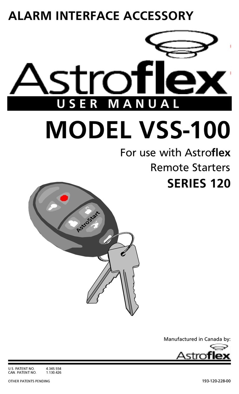
Astroflex 500 Series User manual

REMOTE
CONTROL
ENGINE
STARTER
InstallationManual
FOR
ALLAUTOMATIC
TRANSMISSIONGAS-AND
DIESELPOWEREDVEHICLES.
SERIES
500, 1100,
2100, 4100
NOT FOR USE ON VEHICLES EQUIPPED
WITH MANUAL TRANSMISSION!
THIS PRODUCT MUST BE INSTALLED
BY AQUALIFIED INSTALLER.
(Instructions en français au verso)
PATENTNUMBERS
CAN 1.130.426
USA: 4.345.554 - 5.614.883
5.617.819 - 5.673.017
AND OTHER PATENTS PENDING
Litho’d in Canada
All rights reserved © Astroflex 2000 193-127-200-01
MANUFACTURED IN CANADA BY:
DÉMARREUR
À
DISTANCE
Manueld'installation
SÉRIES
500, 1100,
2100, 4100
NE FONCTIONNE PAS SUR LES VÉHICULES
À BOÎTE DE VITESSES MANUELLE.
L'installation de ce produit doit être
effectuée par du personnel qualifié.
(English instructions on reverse)
NOS. DE BREVETS
CAN 1.130.426
É.-U.: 4.345.554 - 5.614.883
5.617.819 - 5.673.017
ET AUTRES BREVETS EN INSTANCE
Lithographié au Canada
Tous droits réservées © Astroflex 2000 193-127-200-01
Manufacturé au Canada par:
CONÇU POUR TOUT
VÉHICULEAUTOMOBILE
ÀESSENCEOUDIESELETÀ
TRANSMISSIONAUTOMATIQUE

TableofContents
Quick Guide for Professionals 2
Quick Programming 6
Quick Programming Charts 7
(LEVEL1and 2)
Transmitter Coding 7
Tachometer&CylinderSettings 7
Detailed Programming 8
Programming Tables 9
(LEVEL3 through15)
Diagnostic Codes 12
Detailed Features 12
P2 : INPUT/OUTPUT 12
P2-1 &2 : Red 12
P2-3:White/orange: PARK /NEUTRALINPUT 12
P2-4:White/green: POSITIVEBRAKESWITCHINPUT 13
P2-5:Orange/white: WAIT TOSTART(Glowplug) 13
P2-6:Darkgreen: NEGATIVEOUTWHENRUNNING 13
P2-7:Orange: ANTI THEFTOUTPUT 14
P2-8 : Light green: HORN OUTPUT 14
P2-9 : Red/white: +12V OUTPUT 15
P2-10:Black/green: TACHOMETERINPUT 15
P2-12 : Black/red: HOOD INPUT 16
P2-11 : Black: GROUND 16
P2-13:Brown: PROGRAMMABLEOUTPUT#1 17
P2-14:White/blue: PROGRAMMABLE OUTPUT#2 17
P2-15:White: PROGRAMMABLEOUTPUT#3 17
P2-16:Purple: PROGRAMMABLEOUTPUT#4 17
P3 : POWER DOOR LOCKS 17
P4 : MAIN POWER 18
P4-1:Red: POWERINPUT 18
P4-2:Yellow: ACCESSORYOUTPUT 18
P4-3:Green: PARKINGLIGHTOUTPUT 18
P4-4 : Orange: IGNITION OUTPUT 18
P4-5:Darkblue: STARTEROUTPUT 18
P4-6:Lightblue: STARTERKILLINPUT 19
P4-7:Red: POWERINPUT 19
P5 : ON-BOARD PROGRAMMABLE RELAY 19
P10 - P17 : CONNECTORS FOR PLUG-IN ACCESSORIES 19
P10: TIMERCONTROL 19
P11:VALETSWITCH 19
P13 : ON / OFF SWITCH 20
P14 : UNLOCK / LOCK CONNECTOR 20
P15:ANTENNACONNECTOR 20
P16:ORIGINALALARMINTERFACINGCONNECTOR 20
P17:PARKTABCONNECTOR 20
MAIN HARNESS TEST 21
POST-INSTALLATION TESTS 22
ADDITIONAL TRANSMITTER CODING 22
Tabledesmatières
Guide abrégé pour installateurs qualifiés 2
Programmation abrégée 6
Tableaux de programmation abrégée 7
(NIVEAUX1et 2)
Apprentissagedescodesdetélécommandes 7
Réglagedutachymètreet de la cylindrée 7
Programmation détaillée 8
Tableaux de programmation 9
(NIVEAUX3à 15)
Codes diagnostiques 12
Caractéristiques détaillées 12
P2 : ENTRÉE/SORTIE 12
P2-1 et 2 : RougeK12
P2-3:Blanc/orange :ENTRÉE «PARK»/NEUTRE 13
P2-4:Blanc/vert:ENTRÉEINTERRUPTEURDEFREIN 13
P2-5: Orange/blanc:BOUGIESDEPRÉCHAUFFAGE 13
P2-6:Vertfoncé:SORTIENÉGATIVELORSQU’ENMARCHE 13
P2-7:Orange : SORTIEANTIVOL 14
P2-8: Vertpâle:SORTIEKLAXON 14
P2-9 : Rouge/blanc : SORTIE +12V 15
P2-10:Noir/vert:ENTRÉETACHYMÈTRE 15
P2-12:Noir/rouge : ENTRÉEDUCAPOT 16
P2-11:Noir:MASSE 16
P2-13: Brun: SORTIEPROGRAMMABLENO1 17
P2-14:Blanc/bleu:SORTIEPROGRAMMABLENO 2 17
P2-15: Blanc:SORTIEPROGRAMMABLENO3 17
P2-16: Violet: SORTIEPROGRAMMABLE NO4 17
P3 : VERROUILLAGE ÉLECTRIQUE DES PORTIÈRES 17
P4 : PRISE PRINCIPALE 18
P4-1:Rouge:ENTRÉED'ALIMENTATION 18
P4-2:Jaune:SORTIEACCESSOIRES 18
P4-3:Vert:SORTIEFEUXDEPOSITION 18
P4-4: Orange:SORTIED'ALLUMAGE 18
P4-5:Bleufoncé:SORTIEDUDÉMARREUR 18
P4-6:Bleupâle:ENTRÉEDUCOUPE-DÉMARREUR 19
P4-7:Rouge:ENTRÉED'ALIMENTATION 19
P5 : RELAIS PROGRAMMABLE 19
P10 - P17 : PRISES DES ACCESSOIRES ENFICHABLES 19
P10:MINUTERIE 19
P11:COMMUTATEUR«VALET» 19
P13:INTERRUPTEURON/OFF 20
P14:PRISEDÉ/VERROUILLAGE 20
P15:PRISED'ANTENNE 20
P16:PRISED’INTERFACAGED'ALARMED'ORIGINE 20
P17:PRISE«PARKTAB» 20
VÉRIFICATION DU CÂBLE PRINCIPAL 21
VÉRIFICATIONS APRÈS INSTALLATION 22
PROGRAMMATION DE TÉLÉCOMMANDES ADDITIONNELLES 22
1
1

Quick Guide for Professionals
This section of the installation manual is intended for experienced installers of
remote starter and mobile security products. Only the most frequently needed
information is included in the following few pages. It has been laid out to allow
you to quickly access connection and operational details to maximize your installa-
tion performance. Since most of the programming is set for popular defaults, you
will not need to make major, complex changes.
The following charts show the purpose of each wire on each connector and lists
the color code and pin position. Each of the first 5 charts are for a single connec-
tor. Thelastchartliststheconnectorsfortheplug-inaccessories.
Wheneveryouencounterawire
that needs further explanation,
orneedtoaccessthevirtually
unlimited programming flexibil-
ity of this Astrostart product, a
reference to the detailed instal-
lation instructions found later in
the manual will allow you to
understand all of the connection
and programming options
available. Additional informa-
tion will be available on the
AstroChartCDROM.
Each wire that provides a
(-) output can supply only
one single Bosch style
automotive relay.
2
2
Guide abrégé pour installateurs qualifiés
Cettesectiondumanueld'installationestdestinéeauxinstallateursexpérimentés
dedémarreurs àdistance et dedispositifs desécurité mobileet necontient que
l'informationla plussouvent requise.Elleest conçuepour accéderrapidementaux
détails relatifs aux connexions et fonctionnalitées du démarreur à distance afin de
simplifier la tâche à l’installateur.
Comme les réglage de programmation par défaut conviennent à la plupart des
applications,aucune modification d'importancen'est requise.
Lestableauxquisuiventindiquentlafonctiondesfils dechacunedesprises et
donnent le code couleur et la position des broches. Chacun des cinq premiers
tableaux s’appliquent à une
seuleprise.
Lederniertableauprésenteles
prisespouraccessoires
enfichable.
Siunedesconnexionsrequiert
plusd'explications,ousivous
désirezexploitertoutesles
possibilitésqu'offreceproduit
AstroStart,consultezlasection
relative à l'installation détaillée
plus loin dans ce document. On
y décrit plus en détail les
connexionsetlesoptionsde
programmation disponibles.
D'autresrenseignementssont
disponiblessurlecédérom
AstroChart.
Chaque fil qui procure une
sortie (-) peut alimenter un
seul relais de type Bosch.

P2 CONNECTOR (models 500, 1100, 2100, 4100)
Note: Programmable outputs #1 & #2 (P2-13 & 14) also appear on the P16
connector. If you need programmable outputs while P16 is being used with
different settings, use programmable outputs #3 & #4 instead (P2-15 & 16).
3
3
CONNECTEUR P2 (modèles 500, 1100, 2100, 4100)
Remarque : Les sorties programmables 1 et 2 (P2-13 et 14) se retrouvent
également sur la prise P16. Si vous avez besoins de sorties programmable et
que la prise P16 est utilisée avec des réglages qui diffèrent des sorties
programmables 1 et 2, utilisez plutôt les sorties programmable 3 et 4 (P2-15
et 16).
NIPEMANROLOCESOPRUP
1- deR!tucronipaTtoNoD-A/N
2- deR!tucronipaTtoNoD-A/N
3/kraP lartueN tupnihctiwS
/etihW egnarO ebtsumti;ecivedytirucesafotrapsitiucricsihT.rotceteDytefaSlartueN/kraP .tinuniamnobaTkraP71Potdetcennoc
4ekarB )+( /etihW neerG
tupnI tratsetomerlecnactupniotelcihevehtfotiucricthgilekarbehtotdetcennoc tsum-TIUCRICYTEFAS.hctiwslecnaclortnocesiurcotnitcennoctonoD.noitarepo !detcennoceb
5rogulPwolG tratSdeyaleD )±(
/egnarO etihW
tupnI leseid(gulpwolGlitnuedomybdnatsniniamerottratsetomerswolla ).ces06otpu(.flestistaeherp)enigne .)+(sitluafeD enigneeht,detcennocnutfelfI .)3LEVELees-.ces03rofelbammargorp(.ces06retfatratslliw
6)-(tuptuO gninnurnehw neergkraD tuptuO noitingiehterofebs1detavitcA.secivedtfehtitnaMEOhtiwecafretniotdesu .ffotuhssinoitingiretfas1litnusniamerdna,tiucric
7)-(tfehtitnAegnarO tuptuO DELrotiucrictfehtitnanalortnocotdesu .)41egapno"TUPTUOTFEHTITNA"ees(
8)-(nroHneergthgiL .)005tpecxE( tuptuO nA.tuptuolevelwolasisihT.nrohyrotcafehtetavitcaotdesu selcihevniatrecnoderiuqerebyamyalerlanretxe )sliatedlannoitiddarof41egapees(
9V21+etihW/deR tuptuO naybdetcetorP.)slioc(syalerlanoitiddarofstloV21+desufedivorpotdesu )snoitacilpparetratSdn2ronoitingIdn2roftoN:etoN(A1fo)CTP(esufteserotua
01tupnihcaT /kcalB neerG )langishcat(langisdeslupasedivorptahtelcihevnitiucricotdetcennoC .MPR008,lyc1:tluafeD .snoitpognimmargorprof51egaPeeS
11dnuorGkcalBottcennoC.dnuorGniaM lenapkciktfel ro llawerifylno .
21 nipdooH .O.N)±(tupni .C.Nro deR/kcalB ytiralopelbammargorP tupni .doohehtfogninepotcetedotdesu .nepodoohnehwdesolcyllamroN:tluafeD !detcennocebtsum-TIUCRICYTEFAS.snoitpognimmargorprof61egaPeeS
31 -margorP )-(elbam 1#tuptuo nworB evitageN tuptuo .trahcsihtwolebetoneeS.yalerlortnocot1# tratSerofeBesluP:tluafeD ..snoitpognimmargorprof71egaPeeS
41 -margorP )-(elbam 2#tuptuo
/etihW eulB
evitageN tuptuo .trahcsihtwolebetoneeS.yalerlortnocot2# .tratSretfAesluP:tluafeD .snoitpognimmargorprof71egaPeeS
51 -margorP )-(elbam 3#tuptuo etihW evitageN tuptuo .yalerlortnocot3# .esaeleRknurT:tluafeD .snoitpognimmargorprof71egaPeeS
61 -margorP )-(elbam 4#tuptuo elpruP evitageN.)005tpecxE( tuptuo .yalerlortnocot4#
.thgiLemoD:tluafeD .snoitpognimmargorprof71egaPeeS
EHCORBMONRUELUOCNOITASILITU
1- eguoR!repuocsapentenoitavirédederiafysapeN-A/N
2- eguoR!repuocsapentenoitavirédederiafysapeN-A/N
3ruetatummoC ertuen/»kraP«/cnalB egnarO eértnE fitisopsidnu'deitraptiaftiucriceC.ertuen/»kraP«étirucésedruetcetéD- .lapicnirpeludomua»baTkraP«71PàéhcnarbertêtiodlI.étirucésed
4nierF )+( /cnalB treV
eértnE ruopelucihévudtêrra'dxuefsednoitatnemila'dtiucricuaeéhcnarb noitalunna'druetatummocuarehcnarbsapeN.ecnatsidàegarramédelresilartuen .essetivedruetalugérud !eriotagilbotnemehcnarb-ÉTIRUCÉSEDTIUCRIC
5edeiguoB )±(egaffuahcérp /egnarO cnalB
eértnE sednoitcnitxeà'uqsujecnatsidàegarramédelredrateredtnattemrep ,iS.ces06à'uqsujrerudtuepialédeC.)leseidruetom(egaffuahcérpedseiguob àelbalgér(.ces06edialédnu'demretuaeutceffe'segarramédel,eédroccarnon .)noitammargorpaled3uaevinua.ces03 .)+(evitisopétiralop;tuafédrapruelaV
6)-(eitroS ne'uqsrol ehcram écnoftreV eitroS eltnava.ces1eévitcA.enigiro'dlovitnasfitisopsidselrecafretniàtnavres tiucricudnoitavitcasédalsèrpa.ces1à'uqsujeévitcaeruemeD.egamulla'dtiucric .egamulla'd
7lovitnA )-( egnarO eitroS LEDenuuolovitnatiucricnurednammocàtnavres .)41egapalà»LOVITNAEITROS«riov(
8noxalK )-( elâptreV .)005fuaS( eitroS .tnaruocelbiafàeitroS.elucihévudnoxalkelrevitcaàtnavres 41egapriov(selucihévsniatrecruseriassecénertêtuepenretxesialernu'dtuoja'L .)sliatédedsulpruop
9V21+ /eguoR cnalB
eitroS ed)CTP(euqitamotuatnemehcnelcneéràelbisufnurapeégétorpV21+ed .)senibob(seriatnemélppussialersedruoppma1 euqrameR ruopresilitusapen:
.egarraméde2uoegamullae2edsnoitacilppasel
01 udeértnE ertèmyhcat /rioN treV
.)hcatedlangis(noislupmi'dlangisnutinruofiuqelucihévudtiucricuaéhcnarB nim/rt008,lyc1:tuafédrapruelaV ..51egapnenoitammargorpedsnoitposelrioV
11essaMrioN uatnemeluesredroccaR.elapicnirpessamalàesiM larétaluaennap uoehcuaged
alàegufingieiorap.
21 edruetpurretnI .O.N)±(topac .F.Nuo
/rioN eguoR
eértnE -.topacuderutrevuo'lrelecédruopelbammargorpétiraloP émreftnemelamroN:tuafédrapruelaV selrioV.)trevuotsetopaceleuqsrol(
.61egapnenoitammargorpedsnoitpo !eriotagilbotnemehcnarb-ÉTIRUCÉSEDTIUCRIC
31 )-(eitroS -margorp 1onelbam nurB eitroS .sialernurednammocruop1on)-(elbammargorp .suossed-iceuqrameralrioV .egarramédtnavanoislupmI:tuafédrapruelaV rioV
.71egapnenoitammargorpedsnoitposel
41 )-(eitroS -margorp 2onelbam
/cnalB uelB
eitroS .sialernurednammocruop2on)-(elbammargorp .suossed-iceuqrameralrioV egarramédsèrpanoislupmI:tuafédrapruelaV.rioV
.71egapnenoitammargorpedsnoitposel
51 )-(eitroS -margorp 3onelbam cnalB eitroS .sialernurednammocruop3on)-(elbammargorp .suossed-iceuqrameralrioV erffocuderutrevuO:tuafédrapruelaV.selrioV
.71egapnenoitammargorpedsnoitpo
61 )-(eitroS -margorp 4onelbam teloiV .)005fuaS( eitroS alrioV.sialernurednammocruop4on)-(elbammargorp .suossed-iceuqramer .reinnofalP:tuafédrapruelaV edsnoitposelrioV
.71egapnenoitammargorp

NOTE:FORALLABOVEWIRESPLEASESEEPAGE17FORFURTHERDETAILS
Note: TheP3 Connectoraccesses twofullyprogrammable Boschstyle relays
that are intended for power door lock interface.
4
4
P3 CONNECTOR (models 1100, 2100, 4100)
P4 CONNECTOR (models 500, 1100, 2100, 4100)
REMARQUE:CONSULTERLAPAGE17POURPLUSDEDÉTAILSCONCERNANT
LESFILSDECETABLEAU.
Remarque :LeconnecteurP3donneaccèsàdeuxrelaisàfonctionprogrammablede
typeBoschquivisentl’interfaceduverrouillageélectriquedesportières.
EHCORBMONRUELUOCNOITASILITU
103-nummoCnurB.)EGALLIUORREV(hcsoBepyteddradnatssialerud03ehcorB
2A78-.F.NnurB/cnalB.)EGALLIUORREV(hcsoBepyteddradnatssialerudA78ehcorB
378-.O.NcnalB/nurB.)EGALLIUORREV(hcsoBepyteddradnatssialerud78ehcorB
403-nummoCuelB.)EGALLIUORREVÉD(hcsoBepyteddradnatssialerud03ehcorB
5A78-.F.NuelB/cnalB.)EGALLIUORREVÉD(hcsoBepyteddradnatssialerudA78ehcorB
678-.O.NcnalB/uelB.)EGALLIUORREVÉD(hcsoBepyteddradnatssialerud78ehcorB
CONNECTEUR P3 (modèles 1100, 2100, 4100)
NIPEMANROLOCESOPRUP
103-nommoCnworB.)KCOL(yalerepythcsoBevitomotuadradnatsfo03niP
2a78-CNnworB/etihW.)KCOL(yalerepythcsoBevitomotuadradnatsfoa78niP
378-ONetihW/nworB.)KCOL(yalerepythcsoBevitomotuadradnatsfo78niP
403-nommoCeulB.)KCOLNU(yalerepythcsoBevitomotuadradnatsfo03niP
5a78-CNeulB/etihW.)KCOLNU(yalerepythcsoBevitomotuadradnatsfoa78niP
678-ONetihW/eulB.)KCOLNU(yalerepythcsoBevitomotuadradnatsfo78niP
EHCORBMONRUELUOCNOITASILITU
1eértnE noitatnemila eguoR «etnemilA.)1F(pma03edelbisufnurapeégétorp,V21+eértnE .»écnofuelblif-ruerraméD«te»enuajlif-seriosseccA
2eitroS seriossecca enuaJ)ruesitamilc/ettereffuahc(elucihévudseriossecca'dtiucriceletnemilA
3edxuefeitroS noitisop treV edxuefsedtiucriceletnemilA.)3F(A01edelbisufnurapégétorP .noitisop
4eitroS egamulla egnarO edfitisopsidnu'deitraptiafeitrosetteC.egamulla'dtiucriceletnemilA ellE.étirucéstiod eéhcnarbertêtnemetcerid egamulla'dtiucricua
.elucihévudlapicnirp
5eitroS ruerramédécnofuelB
.elucihévud»egarraméd«tiucricuaehcnarbeS .)tnemelues0014te0012:ruerraméd-epuoCnoitpO( .elucihévudegarramédedtiucricud»ruerraméd«étôcudehcnarbeS resilartuenedtemreP.»egamulla«lifelrapeédnammoctseeitrosetteC ecnatsidàegarramédudtnemomuaelucihévudegarramédedtiucricel emmoctnemelagéeésilitU.esirpneertne'nruerramédeleuqretivéruop .lovitnafitisopsid
6-epuoceitroS ruerramédelâpuelB elucihévudegarramédedtiucricud»tcatnocedélc«étôcudehcnarbeS .lovitnafitisopsidemmoctnemelagéeésilitU.)tnemelues0014,0012(
7eértnE noitatnemila eguoR noitisopedxueF«te»egnarolif-egamullA«etnemilaiuqV21+eértnE .)2F(pma03edelbisufnurapeégétorP.»trevlif-
CONNECTEUR P4 (modèles 500, 1100, 2100, 4100)
NIPEMANROLOCESOPRUP
1tupnirewoPdeR seilppus,)1F(esufA03aybdetcetorp,tupnirewopV21+ ."eriWeulBkraD-retratS"ehtdna"eriWwolleY-yrosseccA"
2yrosseccA tuptuo wolleY.)tiucricCA/retaeH(tiucricyrosseccaelcihevsdeeF
3gnikraP tuptuothgil neerG.tiucricthgilgnikrapdeefotdesu,)3F(esufA01aybdetcetorP
4noitingI tuptuo egnarO ti;ecivedytirucesafotrapsitiucricsihT.tiucricnoitingisdeeF tsum eb
detcennoc yltcerid .tiucricnoitingis'elcihevot
5retratS tuptuo eulBkraD
.tiucric"retratS"elcihevotstcennoC .)ylno0014dna0012-noitpollikretratS( ybdellortnocsituptuosihT.tiucricrotomretratsfoedisretratsotstcennoC sielcihevnehwffotuhsebottiucricretratsswollA.eriw"noitingi"eht sedivorposlA.rotomretratseht"gnidnirg"tneverpotdetratsetomer .noitcnuftfehtitna
6-retratS tuptuolliK eulBthgiL desuoslA.)ylno0014,0012(.tiucricrotomretratsfoedisyekotstcennoC .edomtfehtitnArof
7tupnirewoPdeR neerG-sthgiLkraP"ehtdna"eriWegnarO-noitingI"sdeefhcihwtupniV21+ .)2F(esufpmA03aybdetcetorP."eriW

P5 CONNECTOR (models 1100, 2100, 4100)
The default is set for Ignition. (Level 13) Power supply for this circuit must be
protected with an appropriate fuse.
PLUG-INACCESSORIESCONNECTORLIST
5
5
EHCORBMONNOITASILITU
103-NUMMOChcsoBepyteddradnatssialerud03ehcorB
2A78-.F.NhcsoBepyteddradnatssialerudA78ehcorB
378-.O.NhcsoBepyteddradnatssialerud78ehcorB
RUETCENNOC RUOP ELÈDOM MONNOITASILITU
01PSUOT edeiretuniM egarraméd
temrepiuqsehcorbertauqàruetcennoC edemètsyselcevaeiretunimenurecafretni'd .)xelfortsAzehcelbinopsid(ecnatsidàegarramédruop).ces7,0(evitagénnoislupmienutreiuqeR .egarramédelrehcnelcné
11P 0012 0014 telaVruetpurretnI nurehcnarbruopsehcorbsiortàruetcennoC .»telav«ruetpurretni
31PSUOT ruetpurretnI FFO/NO
edsnoitcnofselresilartuenàtnavresruetpurretnI sialerselednammoC.ecnatsidàegarraméd.»ruerramédteseriossecca,egamulla«
41P005 egalliuorrevéDegalliuorreV
tnemehcnarbruopsehcorbsiortàruetcennoC sedàuo1-ALDecafretni'deludomnuàtcerid retnemilaruoptnaruocelbiafàsevitagénseitros edeuqinunoislupmI:tuafédrapruelaV.sialersed edsap,euqitamotuaegalliuorrevedsap,.ces7,0 nenoitammargorpedsnoitposelrioV.noitamrifnoc .11egap
51PSUOT /ennetnA ruetpecérehcnarbesiuqsehcorbsertauqàruetcennoC .ruetpecér/FRennetnaeludomuatnemetcerid
61PSUOT
eludoM egaçafretni'd /ruetasilibommi emrala
qsehcorbtiuhàruetcennoCehcnarbesiu
tnemetceridemrala'degaçafretni'deludomnuceva iuqsliatédselriov(XELFORTSAruetasilibommi/ .)eludomeltnengapmocca
71PSUOT »batkraP«noitcetédaltnattemrepsehcorbxuedàruetcennoC egarramédelrinevérpruopsessetivedreivelud .éyarbmeeuqsrolelucihévud
CONNECTEUR P5 (modèles 1100, 2100, 4100)
La valeur par défaut est réglée pour Allumage (niveau 13). L’alimentation de ce
circuit doit être protégée par un fusible de calibre assortie.
LISTEDESCONNECTEURSPOURACCESSOIRESENFICHABLE
ROTCENNOC
ROF LEDOM EMANESOPRUP
01PLLA DETACIDED REMIT LORTNOC
eboteludomremitlanoitponagniwollarotcennocnip-ruoF .)XELFORTSAmorfelbaliava(tratsetomerehthtiwdecafretni tratsetomerezilaitiniot).ces7.0(eslupevitagenaseriuqeR .erudecorp
11P00140012HCTIWSTELAV telavrofdellatsniebothctiwsagniwollarotcennocnip-eerhT .snoitcnuf
31PLLA FFO/NO HCTIWS .ffosnoitcnuftratsetomerehtnrutotelbaebotdesuhctiwS .syaler"retratsdnaseirossecca,noitingi"slortnoC
41P005 /KCOL KCOLNU
ecafretni1-ALDaotyltceridtcennocotrotcennocnip-eerhT :tluafeD.syalerevirdotstuptuotnerrucwolevitagenro,eludom eeS.noitamrifnoCon,kcolotuAoN,eslupdnoces7.0elgniS .snoitpognimmargorprof11egaP
51PLLA /ANNETNA REVIECER /annetnaFRehtotniyltceridsgulptahtrotcennocnip-ruoF .eludomreviecer
61PLLA
/MRALA REZILIBOMMI GNICAFRETNI ELUDOM
XELFORTSAnaotyltceridtcennocotrotcennocnip-thgiE .eludomgnicafretnirezilibommi/mrala .)eludomehthtiwdegakcapsliatedrehtrufeeS(
71PLLABATKRAP othctiwsrotcelesraegfonoitcetedgniwollarotcennocnip-owT .raegnitratst'nowelciheverusne
NIPEMANESOPRUP
103-NOMMOCyalerepythcsoBevitomotuadradnatsfo03niP
2a78-CNyalerepythcsoBevitomotuadradnatsfoa78niP
378-ONyalerepythcsoBevitomotuadradnatsfo78niP

Quick Programming
You may believe that a product as versatile as the AstroStart would be a program-
ming nightmare. In most cases, you will not need to change from the factory
default programming. In addition, Astrostart’s sophisticated processor allows
direct entry into a multitude of programming options with little effort.
All programming is performed through a 9 button DIP switch module. The
programming options for any feature are presented in the individual feature
explanation, which means there is no need to refer to a confusing but compre-
hensive master programming chart.
Will I Need To Reprogram a Feature?
Consult the following chart to determine if the defaults work for the installation. If
this chart reveals no required changes, move to the testing phase of the installa-
tion on page 21.
If changes to the default programming are required, please become familiar with
the following information in the programming charts.
6
6
Programmation abrégée
On pourrait croire qu'un produit aussi polyvalent que l'AstroStart poserait des
difficultés de programmation importantes. Il n'en est rien. Dans la plupart des cas,
aucunemodification desréglages par défautn'est nécessaire.De plus,grâce àson
processeurperfectionné,l'accèsdirectauxdiversesoptionsdeprogrammationse
faitsans difficulté.
Laprogrammation s'effectuepar l'entremised'unmodule à9commutateurs DIP.
Lesoptionsdeprogrammationpourchaquecaractéristiquesontprésentéesdans
lesinstructions quis'y rattachent,ce quiévite d'avoirà consulterun tableaude
programmation exhaustif et bien souvent déroutant.
Est-ce que je doit reprogrammer une option?
Référez-vousau tableauqui suitpour déterminersi lesréglages pardéfaut
conviennentàl'installationencours.Siaucunchangementn'estrequis,passezà
l'étape de vérification à la page 21.
EIROGÉTACSEÉDNAMMOCTUAFÉDRAPSNOITPO UAEVIN
sednammocéléTedegassitnerppa'lisfuasnoitacifidomenucua-ecivresneednammocéléT.eriassecéntseseriatnemélppussednammocélét1
ruetom/hcaT.nim/rt008editnelaredessetiv,erdnilyc1 2
udnoitarugifnoC ruetom udruetpurretni-egarramédedselcycselertneépuocegamulla-ecnesseàruetoM .trevuotsetopaceleuqsrolémreftopac 3
lovitnasemètsyS lovitna-noitcnofsrohtnememraér-egarramédsèrpaseriossecca'dialédedsaP .noitcnofsroh 4
seitroS selbammargorp )1onelbammargorpeitros(tnavanoislupmI 5
seitroS selbammargorp )2onelbammargorpeitros(sèrpanoislupmI 6
seitroS selbammargorp )3onelbammargorpeitros(erèirraerffoC 7
seitroS selbammargorp )4onelbammargorpeitros(reinnofalP 8
sialeR elbammargorp )elbammargorpnoitcnofàsialer(egamullA 9
edsnoitpO egalliuorrev -.ces7,0edegalliuorrev/édednoislupmI,.ces7,0edegamullAtnavAnoislupmI ednoitamrifnoc-elpmis=egalliuorrevédednoislupmi-noitcnofsrohegalliuorrevotua .noitcnofsrohegalliuorreve2 01
seriatilituseitroS udeérud-.ces7,0ed2oneriatilitunoislupmi-.ces7,0ed1oneriatilitunoislupmI .)tnemeluessnotuob6àednammocélét-noitcnofne(.ces03ed»euqinap«edom 11
ehcramedspmeT.setunim61=leseid-setunim8=ecnessE 21
ellenitnesedoM 8=ecnesse:ehcramedspmet-)F°5(C°51=ellenitnesedomuderutarépmeT .setunim61=leseid-setunim 31
àsednammocéléTsnotuob2
)temelues205elèdom(snotuob2àsednammocélétsedegadocéD
)FFO/NO(ELLENITNESTÊRRAEGARRAMÉD51
Sideschangementss'imposent,familiarisez-vousaveclestableauxde
programmation qui suivent et l'information qu'ils renferment.
CIPOTDELLORTNOCSERUTAEFTLUAFED LEVEL
srettimsnarT .denraelebtsumsetomerlanoitiddasselnuderetlaton-elbanEetomeR 1
enignE/hcaTdeepseldiMPR008,rednilyc1 2
enignE noitarugifnoC tcatnocdesolchctiwsdooH,selcycknarcneewtebffotucnoitingI,elcihevenilosaG .neposidoohnehw 3
tfehtitnA ytilibitapmoC ffotfehtitnA,ffognimraeR,putratsretfayaledyrosseccaoN 4
elbammargorP stuptuO )1#tuptuoelbammargorp(erofebesluP 5
elbammargorP stuptuO )2#tuptuoelbammargorp(retfaesluP 6
elbammargorP stuptuO )3#tuptuoelbammargorp(knurT 7
elbammargorP stuptuO )4#tuptuoelbammargorp(thgilemoD 8
elbammargorP yaleR )yalerelbammargorp(noitingI 9
kcoLrooD snoitpO -eslupgnikcolnU,ffokcolotuA,eslupkcolnu/kcol.ces7.0,noitingIerofebeslup.ces7.0 ffonoitamrifnoceslupgnikcoLdn2,elgnis 01
stuptuOytilitU noitarudcinaPdnoces03,2#eslupytilitudnoces7.0,1#eslupytilitudnoces7.0 )ylnosetomernottub6-nO( 11
emiTnuRenignEemitnur.nim61-leseiD,.nim8-enilosaG 21
pmeTlenitneS emiTnuR& leseidnim61-,sagnim8-lenitnesemitnuR,)Fº5(Cº51-erutarepmetedomlenitneS 31
setomeRnottuB-2
)ylno205ledom(gnidocedrettimsnartetomernottuB-2
)ffo/no(LENITNES=POTS=TRATS= 51
Quick Programming Charts
(LEVEL 1 and 2)
This information assumes that you understand how to program an Astrostart. If
not, refer to Detailed Programming.
In most cases you will need to program only the tachometer and cylinder setting,
and occasionally a remote transmitter.
Transmitter Coding
Intheeventthata transmitterneeds tobe re-coded,the followingtable outlinesthe
settings.
Tachometer & Cylinder Settings
Level2programmingsetsbothIDLINGSPEEDandthevehicle’snumberofcylin-
ders(pertachsignal).
In almost all cases, it is best to
start with the Auto Learn capabil-
ity.Seeprocedure onpage15.
TRANSMITTERCODING
7
7
hctiwSPID1LEVEL 56789
teseRgnimmargorPlaitinI
òò PU òò
gninraeLrettimsnarT
òòò PU ò
noitarepOlamroN
òòòòò
LEVEL1
LEVEL2
ONCEDIP SWITCHES ARESET, PRESSBRAKE PEDALTO“LEARN”THE
FUNCTIONS.
Tableaux de programmation abrégée
(NIVEAUX 1 et 2)
Les renseignements qui suivent supposent que vous savez comment programmer un
démarreur AstroStart. Si tel n'est pas le cas, consultez la section relative à la programmation
détaillée.
En général, il suffira de programmer les réglages du tachymètre et du nombre de
cylindres, et parfois une télécommande.
Apprentissage des codes de télécommandes
Si une télécommande doit être reprogrammée, le tableau qui suit indique les réglages
qui sont requis.
Réglage du tachymètre et de la vitesse de ralenti
La programmation du niveau 2 permet de régler à la fois la vitesse de ralenti et le
nombre de cylindres (par circuit d’allumage).
En général, il est préférable de
procéder avec l'option
d'autoapprentissage d'abord.
UNEFOISLERÉGLAGEDESCOMMUTATEURSDIPEFFECTUÉ,APPUYEZSURLA
PÉDALEDEFREINPOURQUELAFONCTIONSOITMÉMORISÉE.
NIVEAU 2
NIVEAU 1 APPRENTISSAGEDETÉLÉCOMMANDES
1UAEVIN 56789
)teser(selaitininoitammargorP òòéòò
sednammocélétedegassitnerppA òòòéò
lamrontnemennoitcnoF òòòòò
2UAEVIN 56789
erdnilyc1 ò ò ò
serdnilyc2 éòò
serdnilyc4-3 òéò
serdnilyc6-5 ééò
serdnilyc8 òòé
serdnilyc01 éòé
serdnilyc21 òéé
.hcategassitnerppaotuA ééé
.nim/rt008 ò ò
.nim/rt006 éò
.nim/rt005 òé
TACHYMÈTREET CYLINDRÉE
hctiwSPID2LEVEL56789
rednilyC1
ò ò ò
rednilyC2
PU òò
rednilyC4-3
òPU ò
rednilyC6-5
PUPUò
rednilyC8
òò PU
rednilyC01
PU òPU
rednilyC21
òPUPU
hcaTnraeLotuA
PUPUPU
MPR008
ò ò
MPR006
PU ò
MPR005
òPU
TACH&CYLINDERS

Detailed Programming
ProgrammingisverysimpleonceyouhaveprogrammedyourfirstAstrostart.
Programmingparametersaredividedinto15groupscalled"levels"(seeprogram-
ming tables, pages 9 to 12). These parameters are selected by setting a series of
9 DIP switches.
DIP switches 1, 2, 3 and 4 are used to
select programminglevels.......
Ineachlevel,allparametersmustbeprogrammedinasingleprogrammingstep.
Programmingisaccomplishedasfollows.
1) Set DIP switches 1, 2, 3 and 4 to select the feature’s LEVEL.
2) Set DIP switches 5 to 9 to combine options you wish to select.
3) Apply brakes to lock in the selected parameters in memory. LED flashes
same number of times as programming level selected, confirming that
parametershavebeenmemorizedinthatLEVEL.
3a) Repeatsteps1to3 foreachLEVELthatrequiresprogrammingchanges.
4) Whenprogramming iscomplete, put allDIP switches backto "OFF"
position, then apply brakes.
NOTE:IFYOUHAVETOMAKEANYPROGRAMMINGCHANGESINONE
LEVEL,THEENTIRELEVELMUSTBEPROGRAMMED.
EXAMPLE
Imagine you have to program the Astrostart for an eight cylinder engine, with an
idlespeed of600RPM.
1) PlaceDIPswitchesinfollowingposition:
a) DIP switches 1, 2, 3 and 4 for programming level 2.
b)DIP switches 5,6,& 7determine number ofcylinders.
c) DIP switch 8 & 9 determines idle speed.
2) Apply brakes, the LED flashes twice to
confirmlevel2settingshavebeen
memorized.
3) Whenyouhavefinishedprogramming,
return all DIP switches to the OFF, then
applybrakesorselectnext level.
...while DIP switches 5 to 9 are
used to select options in each level.
8
8
Programmation détaillée
La programmation est très simple après avoir effectué la programmation du premier
module de commande.
Lesoptionsdeprogrammationsontregroupées en15niveaux(consulterlestableaux
de programmation, page 9 à 12). Le choix des options se fait en réglant une série de
9commutateursDIP.
LescommutateursDIP1à4permettent
de choisir le niveau de programmation.....
Àchaque niveau, ilfaut programmer tous lesparamètres en uneseuleétape de
programmation.
Laprogrammations'effectuecommesuit:
1) RéglezlescommutateursDIP1,2,3et4enfonctionduNIVEAUde
l'optiondésirée.
2) RéglezlescommutateursDIP5à9selonlesOPTIONSdésirée.
3) Appuyezsur lapédale de frein pourenregistrer en mémoireles
paramètreschoisis.LaDEL clignoteunnombredefois correspondantau
niveau de programmation choisi pour confirmer l'enregistrement des
optionsdeceNIVEAU.
3a) Répétezles étapes 1à3pourchaqueNIVEAU qui doitêtreprogrammé.
4) Unefoislaprogrammationterminée,remetteztous lescommutateursDIP
en position OFF, puis appuyer sur la pédale de frein.
REMARQUE:LENIVEAUENENTIERDOITÊTREREPROGRAMMÉMÊMESIUNSEUL
CHANGEMENTESTEFFECTUÉ.
EXEMPLE:
Supposonsquevousdevez programmerundémarreurAstroStartpourunmoteur8
cylindres, avec vitesse de ralenti à 600 tr/min.
1) RéglezlescommutateursDIPcommesuit:
a) DIP 1, 2, 3 et 4 pour le niveau de
programmation 2.
b) DIP 5, 6 et 7 pour le nombre de
cylindres.
c) DIP 8 et 9 pour la vitesse de ralenti.
2) Appuyezsurlapédaledefrein.LaDEL
clignote deux fois pour confirmer
l'enregistrementdesréglagesduNIVEAU2.
3) Unefoislaprogrammation terminée, ramenez tous les commutateurs DIP à
lapositionOFFpuis,appyezsur lesfreinsoupassezauniveausuivant.
.....tandisque lesDIP 5à 9permettent
dechoisirlesoptionsàceniveau.
RÉGLAGEDESOPTIONS
SÉLECTIONDUNIVEAU
EXAMPLEDERÉGLAGE
SETTINGFEATURES
SETTINGPROGRAMLEVEL
SETTINGEXAMPLE

Programming Tables
(LEVEL 3 through 15)
ThefollowingprogrammingtablesoutlinethesettingsfortheremainingLEVELS.
Note that if you are changing one feature on a LEVEL, all of the other features on
thatLEVELneedtobeplacedinthedesiredpositionsortheywillbereset.
ENGINECONFIGURATION
Diesel: Positive& negativeglow
plug settings are based on the glow
plug light being “ON”.
ANTITHEFTCOMPATIBILITY
Type 1 rearming is suited to North
Americanvehicles, whileType2 is
suitedforAsianand European
vehicles.
9
9
Tableaux de programmation
(NIVEAUX 3 à15)
Les tableaux de programmation qui suivent indiquent les réglages requis pour les
NIVEAUX qui restent. Remarque : même si un seul paramètre doit être réglé, le niveau
doit etre programmé en tenant compte de tous les paramètres qu’il comporte.
Diesel : les réglages positifs et
négatifs relatifs à la bougie de
préchauffage supposent que
son voyant est allumé.
Le réarmement de type 1
convient aux véhicules nord-
américains, tandis que le type 2
convient aux véhicules
asiatiques et européens.
hctiwSPID3LEVEL 56789
enignEenilosaG
ò
enignEleseiD
PU
)ylnoleseiD(etunim1sgulPwolG
ò
)ylnoleseiD(sdnoces03sgulPwolG
PU
tiucricsgulPwolGevitisoP
ò
tiucricsgulPwolGevitageN
PU
stpmettaknarcneewtebffOnruT:noitingI
ò
stpmettaknarcneewtebnOpeeK:noitingI
PU
hctiwsniPdooHdesolCyllamroN
ò
hctiwsniPdooHnepOyllamroN
PU
hctiwSPID4LEVEL 56789
ffO:ytiruceSyrotcaFgnimraeR
ò
nO:ytiruceSyrotcaFgnimraeR
PU
mraeR1epyT
ò
mraeR2epyT
PU
yaledoN-yaleDputratSyrosseccA
ò
yaleddnoces3-yaleDputratSyrosseccA
PU
oN:*metsyStfehtitnA
ò
seY:*metsyStfehtitnA
PU
*tfehtitnAepyTevissaP
ò
*tfehtitnAepyTevitcA
PU
LEVEL4
LEVEL3
* See P2-7 on page 14
* Voir P2-7 en page 14
4UAEVIN 56789
-enigiro'd.tsysudtnememraéRsroHnoitcnof ò
-enigiro'd.tsysudtnememraéRnEnoitcnof é
1epyttnememraéRò
2epyttnememraéRé
ialédsnas-seriosseccasedtiucricneesiM ò
.ces3edialéd-seriosseccasedtiucricneesiM é
:*lovitnaemètsySroHnoitcnofs ò
noitcnofnE:*lovitnaemètsyS é
fissap*lovitnaemètsyS ò
fitca*lovitnaemètsyS é
3UAEVIN 56789
ecnesseàruetoM ò
leseidruetoM é
).luesleseid(.nim1-egaffuahcérpedseiguoB
ò
).luesleseid(.ces03-egaffuahcérpedseiguoB
é
egaffuahcérpedseiguob-fitisoptiucriC
ò
egaffuahcérpedseiguob-fitagéntiucriC
é
egarramédedsevitatnet2ertneeépuoc:egamullA
ò
egarramédedsevitatnet2ertneeunetniam:egamullA
é
émreftnemelamron-topacedruetpurretnI
ò
trevuotnemelamron-topacedruetpurretnI
é
NIVEAU 4 SYSTÈMES ANTIVOL
NIVEAU 3 CONFIGURATIONDUMOTEUR

Defaults for Programmable Outputs:
Output #1= Pulse Before Start
Output #2 = Pulse After Shutdown
Output #3 = Trunk Release
Output #4 = Dome Light
PROGRAMMABLERELAY
DefaultforProgrammableRelay:
Ignition
LEVEL5
LEVEL6
LEVEL7
LEVEL8
Réglagespardéfautdessorties
programmables :
Sortie 1 : impulsion avant démarrage
Sortie 2 : impulsion après arrêt
Sortie 3 : coffre
Sortie 4 : plafonnier
Réglagespardéfautdurelais
programmable :
Allumage
NIVEAU 5
NIVEAU 6
NIVEAU 7
NIVEAU 8
hctiwSPID8&7,6,5LEVEL
tluafeD LEVEL
6789
tratSerofeBesluP )1#tuptuOtluafeD( 5òòòò
nwodtuhSretfAesluP )2#tuptuOtluafeD( 6PU òòò
gninnuRelihWdnuorG òPU òò
sthgiLkraP PUPUòò
putratSretfAesluP òò PU ò
kcolnUdn2noesluP PU òPU ò
noitingI òPUPUò
yrosseccA PUPUPUò
retratS òòò PU
esaeleRknurT )3#tuptuOtluafeD( 7PU ò ò PU
)noitarudetunim1(noitingIretfAnO òPU òPU
thgiLemoD )4#tuptuOtluafeD( 8PU PU òPU
dekcoLelihWdnuorG òò PUPU
1ytilitU PU òPUPU
2ytilitU òPUPUPU
PROGRAMMABLEOUTPUTS1, 2,3&4
hctiwSPID9LEVEL 56789
tratSerofeBesluP òòòò
nwodtuhSretfAesluP PU òòò
gninnuRelihWdnuorG òPU òò
sthgiLkraP PUPUòò
putratSretfAesluP òò PU ò
kcolnUdn2noesluP PU òPU ò
noitingI òPU PU ò
yrosseccA PUPUPUò
retratS òòò PU
esaeleRknurT PU òò PU
)noitarudetunim1(noitingIretfAnO òPU òPU
thgiLemoD PUPUòPU
1ytilitU PU òPUPU
2ytilitU òPUPUPU
8TE7,6,5UAEVIN
uaeviN rap tuaféd
6789
egarramédtnavanoislupmI )1oneitrostuafédrap( 5ò ò ò ò
têrrasèrpanoislupmI )2oneitrostuafédrap( 6é ò ò ò
ehcramneeuqsrolessamalàesiM òéòò
noitisopedxueF ééòò
egarramédsèrpanoislupmI òòéò
egalliuorrevéde2udsrolnoislupmI éòéò
egamullA òééò
seriosseccA éééò
ruerraméDòòòé
erffocuderutrevuO )3oneitrostuafédrap( 7é ò ò é
).nim1eérud(egamullasèrpatiucricnE òéòé
reinnofalP )4oneitrostuafédrap( 8é é ò é
élliuorreveuqsrolessamalàesiM òòéé
1oneriatilitU éòéé
2oneriatilitU òééé
SORTIESPROGRAMMABLES1,2,3ET4
9UAEVIN 56789
egarramédtnavanoislupmI òòòò
têrrasèrpanoislupmI éòòò
ehcramneeuqsrolessamalàesiM òéòò
noitisopedxueF ééòò
egarramédsèrpanoislupmI òòéò
egalliuorrevéde2udsrolnoislupmI éòéò
egamullA ò é é ò
seriosseccA éééò
ruerraméDòòòé
erffocuderutrevuO éòòé
).nim1eérud(egamullasèrpatiucricnE òéòé
reinnofalP ééòé
1oneriatilitU éòéé
2oneriatilitU òééé
RELAISÀFONCTIONPROGRAMMABLE
LEVEL9
NIVEAU 9
10
10

Diesel: Runtimes shownforDiesel
arebasedonLEVEL3 beingpro-
grammed to enable diesel options.
Default: -15°C (5°F), and 8 minutes
(gas)
Diesel: RuntimesshownforDiesel are
basedonLEVEL3beingprogrammed
toenabledieseloptions.
Default: 8 minutes (gas)
Default:
Utility 1 = 0.7 sec.
Utility 2 = 0.7 sec.
Alarm cycle = 30 sec.
Default:
Pulse before ignition = 0.7 sec.
Door Lock Pulse = 0.7 sec.
Autolock = OFF
Unlock Pulse = single
Second Unlock Confirmation = OFF
DURATIONS: UTILITY1&2&PANIC
LOCK/UNLOCKOPTIONS
ENGINERUNTIME
SENTINELTEMPERATURE&RUNTIME
Réglages par défaut :
Imp. Avant Allumage = 0,7 sec.
Déverrouillage = 0,7 sec.
Autoverrouillage = OFF
Déverrouillage = simple
Confirmation = OFF
Réglages par défaut :
Utilitaire 1 = 0,7 sec.
Utilitaire 2 = 0,7 sec.
Cycle de l'alarme = 30 sec.
Réglage par défaut :
8 min. (essence); 16 min.
Diesel
Réglages par défaut :
Température = -15 °C (5°F)
Temps de marche = 8 min.
(essence), 16 min. Diesel
hctiwSPID01LEVEL 56789
.ces7.0=noitarudnoitingIerofebesluP
ò
.ces53.0=noitarudnoitingIerofebesluP
PU
sdnoces7.0=esluPkcoL/nUrooD
ò
sdnoces8.2=esluPkcoL/nUrooD
PU
ffOkcolotuA
ò
nOkcolotuA
PU
esluPkcolnUelgniS
ò
esluPkcolnUelbuoD
PU
FFOnoitamrifnoCkcoLdnoceS
ò
NOnoitamrifnoCkcoLdnoceS
PU
hctiwSPID11LEVEL 56789
sdnoces7.0=1ytilitU
ò ò
etunim1=1ytilitU
PU ò
setunim8=1ytilitU
òPU
sdnoces7.0=2ytilitU
ò ò
etunim1=2ytilitU
PU ò
setunim8=2ytilitU
òPU
sdnoces03=noitaruDcinaP/mralA
ò
sdnoces06=noitaruDcinaP/mralA
PU
hctiwSPID21LEVEL 56789
setunim4leseiD,setunim2saG
òPU
setunim8leseiD,setunim4saG
PUPU
setunim61leseiD,setunim8saG
ò ò
setunim63leseiD,setunim81saG
PU ò
hctiwSPID31LEVEL 56789
pmeTnoitavitcAlenitneS)F°32(C°5-
PUPU
pmeTnoitavitcAlenitneS)F°5(C°51-
ò ò
pmeTnoitavitcAlenitneS)F°7-(C°02-
PU ò
pmeTnoitavitcAlenitneS)F°22-(C°03-
òPU
emiTnuRlenitneS.nim4leseiD,.nim2saG
òPU
emiTnuRlenitneS.nim8leseiD,.nim4saG
PUPU
emiTnuRlenitneS.nim61leseiD,.nim8saG
ò ò
emiTnuRlenitneS.nim63leseiD,.nim81saG
PU ò
01UAEVIN 56789
.ces7,0:egamullatnavanoislupmi'ledeéruD ò
.ces53,0:egamullatnavanoislupmi'ledeéruD é
.ces7,0:serèitropsedegalliuorrev/édednoislupmI ò
.ces8,2:serèitropsedegalliuorrev/édednoislupmI é
noitcnofsroH:egalliuorrevotuA ò
noitcnofnE:egalliuorrevotuA é
:egalliuorrevédednoislupmIelpmiS ò
:egalliuorrevédednoislupmIelbuoD é
noitcnofsroH:egalliuorreve2rusnoitamrifnoC ò
noitcnofnE:egalliuorreve2rusnoitamrifnoC é
OPTIONSDEDÉ/VERROUILLAGE
21UAEVIN 56789
setunim4:leseiD;.nim2:ecnessE òé
setunim8:leseiD;.nim4:ecnessE éé
setunim61:leseiD;.nim8:ecnessE ò ò
setunim63:leseiD;.nim81:ecnessE éò
UAEVIN31 56789
ellenitnesedomudnoitavitca'derutarépmeT ò
)F°32(C°5- éé
)F°5(C°51- ò ò
)F°7-(C°02- éò
)F°22-(C°03- òé
ellenitnesedomudehcramedeéruD ò
.nim4:leseiD;.nim2:ecnessE òé
.nim8:leseiD;.nim4:ecnessE éé
.nim61:leseiD;.nim8:ecnessE ò ò
.nim63:leseiD;.nim81:ecnessE éò
11UAEVIN 56789
ednoces7,0:1eriatilitU ò ò
etunim1:1eriatilitU éò
setunim8:1eriatilitU òé
ednoces7,0:2eriatilitU ò ò
etunim1:2eriatilitU éò
setunim8:2eriatilitU òé
sednoces03:»euqinap«/emrala'ledeéruD ò
sednoces06:»euqinap«/emrala'ledeéruD é
TEMPSDEMARCHE
MODESENTINELLE
LEVEL10
LEVEL11
LEVEL12
LEVEL13
NIVEAU 10
NIVEAU 12
NIVEAU 13
11
11
NIVEAU 11 DURÉES : UTILITAIRES1ET2ET«PANIQUE »

Detailed Features
P2 : INPUT/OUTPUT
P2-1&2 : Red
THESEPINS ARENOTFORINSTALLATIONUSE.DONOTCONNECTTO
ANYTHING!
12
12
Diagnostic Codes
When module is in operating mode (ready to start), the LED may display different
diagnosticcodes for troubleshooting.
COMMAND RECEPTION
The LED flashes rapidly when command is sent to confirm that control module is
receivingremotecontrol signals.
TheLEDflashesacertainnumberoftimes(seetable)afteranunsuccessfulremote
start or run time interruption to indicate the reason for shutdown.
Code Reason for interruption
1 Stopped by remote control (trigger input - P10)
2 Stopped by applying brakes or (-) outputs are overloaded.
4 No tach reading (rpm)
5 Hood open
6 Transmissionnotin"P"or"N"
7 Ignition already in "ON" position
8 Main switch in "OFF" position or thermal protection (P2-9 and/or P10 to
P17overloaded).
9 Runtimeexpired
10 Startcycleexpired
11 Tachsignalalreadypresent
12 RPMabove3000
13 RPMbelowIdling
Codes diagnostiques
Lorsque le module est en mode fonctionnement (prêt pour le démarrage), la DEL
permetde diagnostiquer lesdéfaillancessous forme decode.
RÉCEPTION DE COMMANDE
La DEL clignote rapidement pendant la transmission d'une commande pour
confirmer la réception des signaux par le module de commande.
La DEL clignote par coups (voir le tableau) pour indiquer la raison du passage
hors fonction après une tentative infructueuse de démarrage àdistance ou lors de
l'arrêt du moteur.
Code Raison de l'interruption
1 Arrêt commandépar la télécommande (entrée d'impulsion - P10)
2 Arrêt commandépar appui sur la pédale de frein ou surcharge des
sorties(-)
4 Aucune lecture de tach (tr/min)
5 Capot ouvert
6 Transmissionhorsdu«P»oudu«N»
7Cléde contact déjààla position «ON »
8 Interrupteurprincipal à«OFF »ouprotection thermique(surcharge sur
lesprises P2-9 et/ouP10 àP17).
9 Tempsdemarcheécoulé
10 Cyclede démarrageécoulé
11 Signalde tachdéjàprésent
12 Tr/min supérieur à3 000
13 Tr/minsouslavitessederalenti
Caractéristiquesdétaillées
P2 : ENTRÉE/SORTIE
P2-1 et 2 : Rouge.
CESBROCHESNEDOIVENT PASSERVIRLORSDE L'INSTALLATION.NE
PASS’YRACCORDER!
51UAEVIN 56789
ò ò
éò
òé
TÉLÉCOMMANDEÀ2BOUTONS
Valeur par défaut :
Démarrage - Arrêt -Sentinelle
- - Sentinelle
- - Sentinelle
- -
NIVEAU 15
51LEVEL56789
ò ò
PU ò
òPU
- - Sentinel
- - Sentinel
- -
2-BUTTONREMOTETRANSMITTER
Default :
Start-Stop-Sentinel
LEVEL 15

P2-3 : White/orange: PARK / NEUTRAL INPUT
Groundsignalinputwhichmakesstarting thevehiclepossible whenthis wire
receives a signal from a park/neutral safety switch, or by connecting this wire to the
park tab wire (P-17). It is very important that the vehicle doesn’t remote start
when the gear selector lever is not in park or neutral.
Thiscircuit ispart ofa safetydevice; itmust beconnected!
P2-4 : White/green: POSITIVE BRAKE SWITCH INPUT
This is a safety circuit that tells the control module to abort the starting cycle or to
disengage the module: it must be connected according to instruc-
tionsbelow.
•Connect White/Green wire to brake lights circuit at brake pedal
switch (wire that provides +12 Vdc only when brakes are applied).
•Do not connect White/Green wire to cruise control cancelling
switch.
P2-5 : Orange/white: WAIT TO START (Glowplug)
This circuit is used to delay starting of the vehicle until the preheating of the diesel
engine has taken place. The cranking cycle is delayed until the glow plugs go out.
Find the glow plug light circuit in the dashboard and connect this wire to that
circuit.
Level 3 programming decides the polarity of the glow plug wire, and the glow plug
warm up time as well as the type of engine.
This connection is optional, but is highly recommended for optimal starting. If left
unconnected, the engine will start after 60 seconds regardless of when the engine
is ready. This feature can be programmed to 30 seconds in the LEVEL 3 program-
ming.
The polarity of the glow plug circuit is determined by testing the circuit
with the glow plug light is illuminated.
Refer to Level 3 programming on page 9 for details.
P2-6 : Dark green: NEGATIVE OUT WHEN RUNNING
Negative output used to control original equipment anti theft devices. This output is
activated during the cranking cycle and is powered up 1 second before ignition
until1 second afterignition. Thiscould beused to disablea factorysecurity system
or an anti theft device.
13
13
Blanc/orange : ENTRÉE «PARK »/ NEUTRE ·P2-3
Entréede signalde massequirend possiblele démarragelorsque cefil reçoit un
signalde l'interrupteurde sécurité«Park»/Neutre, oulorsque cefil estbranchéà
«Park Tab »(P17). Il est essentiel que le véhicule ne puisse être démarréà
distance lorsque le levier de vitesses n'est pas en position «P »ou «N ».
Cecircuit faitpartie d'undispositif desécurité. Ildoit êtrebranché!
P2-4 : Blanc/vert : ENTRÉE POSITIVE INTERRUPTEUR DE FREIN
Il s'agit d'un circuit de sécuritéqui sert àneutraliser le cycle de démarrage, il doit
êtrebranchéselonlesconsignesquiapparaissentci-dessous.
•Brancher le fil blanc/vert au circuit des feux d'arrêt au niveau de
l'interrupteur de la pédale de frein (le fil fournit du courant +12Vcc
seulementlorsquelapédalede freinest enfoncée).
• Ne pas brancher le fil blanc/vert àl'interrupteur du régulateur de
vitesse.
P2-5 : Orange/blanc : BOUGIES DE PRÉCHAUFFAGE
Surlesvéhiculesdiesel,cecircuitpermetderetarderledémarragejusqu'au
momentoùle préchauffage estcomplété.Le cyclede démarrage estretardé
jusqu'àcequelesbougiess'éteignent.
Localiser le circuit du voyant de la bougie de préchauffage au tableau de bord et y
brancher le fil.
Leniveaudeprogrammation3 décidedutypedemoteur,delapolaritédu circuitde
labougiedepréchauffage,ainsiquedesadurée.
Cebranchementestfacultatif,maisonlerecommandefortementpourfaciliterle
démarrage. Si le branchement n'est pas fait, le moteur va démarrer après 60
secondes qu'il soit réchaufféou non. Cette option est programmable à30
secondesauNIVEAU3.
La polaritédu circuit de la bougie de préchauffage est déterminée en
testant le circuit alors que le voyant de la bougie de préchauffage est
allumé.
Se référer àla section de programmation àla page 9 pour plus de détails.
P2-6 : Vert foncé: SORTIE NÉGATIVE LORSQU’EN MARCHE
Sortienégativeutiliséepour commanderlesdispositifs antivold'origine.Cette
sortieest activée1 secondeavant le démarrage, elledemeure maintenuependant
le temps de marche puis, est coupé1 seconde après la fin du temps de marche.
Ellepeutserviràmettrehorscircuitunsystèmedesécuritéinstalléenusineouun
systèmeantivol.

AntitheftOutput
P2-7:Orange: ANTITHEFTOUTPUT
Note: On Model 500 do not use if module is not configured to accept
<<UNLOCK>>function.
Negative output used to control a relay
that neutralizes a vehicle circuit to
prevent starting, or an LED to indicate
antitheft status.
Following example illustrates how to
connect a start-disable circuit.
Active Anti theft Mode
When this output is programmed in “ACTIVE”mode, it will become activated when the
locking function is received and deactivated when the unlocking function is received.
Passive Anti theft Mode
When the anti theft output is programmed in “PASSIVE”mode the circuit is deactivated
in the same manner as the active mode, and it is activated 60 seconds after the ignition
switch is turned off. During this delay, if the ignition switch is turned back on, this mode
is then cancelled and the anti theft will wait for another transition from “on”to “off”. Once
the anti theft is activated, turning the ignition back on will not affect the anti theft feature.
In addition, this output is deactivated for 60 seconds if an “UNLOCKING”function is
received. During this delay if the ignition has not been switched from “OFF”to “ON”the
anti theft will remain activated
Anti theft “Valet”Mode
(Models 2100 and 4100 only).
Mode selectable on LEVEL 4, Default OFF. The “Valet”input serves to permanently
control the anti theft output up to 10 cycles of the ignition switch being turned on then off.
The anti theft valet mode will be deactivated by pressing the push button for 3 seconds
while ignition is ON. See P-11 for switch connection.
(Other models)
For other models, it is possible to add a toggle switch in series with the anti theft output
(P2-7) to cancel anti theft function.
P2-8: Light green: HORNOUTPUT
(Except Model 500)
Negative output used to
activate the factory horn
circuit (low current) or an
external relay. Could be
hooked to the vehicles
factory horn to give an
added audible verifica-
tion.
14
14
Sortieantivol
P2-7 : Orange : Sortie antivol
Remarque : Ne pas utiliser sur le modèle 500 si le module n'est pas configurépour
recevoir la fonction «DÉVERROUILLAGE».
Sortie négative permettant de com-
mander un relais qui neutralise un
circuit du véhicule servant àempêcher
le démarrage, ou une DEL pour
indiquer l'état du système antivol.
L'exemple qui suit illustre la manière de
brancher un circuit de neutralisation de
démarrage.
Mode antivol actif
Lorsque cette sortie est programmée en mode «ACTIF », le circuit est activélorsque la
fonction de verrouillage est reçue, et désactivélorsque la fonction de déverrouillage est
reçue.
Mode antivol passif
Lorsque cette sortie est programmée en mode «PASSIF », le circuit est désactivécomme
dans le cas du mode actif, et elle est activée 60 secondes après que la cléde contact est
placée en position «OFF ». Pendant cet intervalle, si la cléde contact est de nouveau placée
à«ON », ce mode est annuléet l'antivol attendra un autre cycle «ON »à«OFF »de la clé.
Une fois l'antivol activé, le fait de remettre la cléde contact àla position «ON »ne va pas
affecter la fonction antivol. De plus, cette sortie est désactivée pendant 60 secondes si une
fonction de «DÉVERROUILLAGE »est reçue. Si, au cours de ce délai, la cléde contact n'a
pas étéramenée de «OFF »à«ON », la fonction antivol va demeurer enclenchée.
Mode antivol «valet »
(Modèles 2100 et 4100 seulement).
Mode sélectionnable au NIVEAU 4. «OFF »par défaut. L’entrée «Valet »permet de com-
mander la sortie antivol de façon permanente et jusqu'àconcurrence de 10 cycles «ON /
OFF »de cléde contact.
Le mode valet antivol est désactivéen appuyant pendant 3 secondes sur le bouton alors que
la cléde contact est en position ON. Voir P-11 pour le branchement de l'interrupteur.
(Autres modèles)
Pour les autre modèles, il est possible d’ajouter un interrupteur de type bascule en série sur
la sortie antivol (P2-7) afin de neutraliser la function «Antivol ».
P2-8 : Vert clair : SORTIE KLAXON
(sauf modèle 500)
Sortie négative servant à
activer le circuit du klaxon
installéen usine (courant
faible) ou un relais externe.
Peut être branchée au klaxon
installéen usine pour offrir
une option de vérification
sonore supplémentaire.
Porte-fusible
P2-8Vert pâle
Circuit d’origine
Vertpâle
IGNITION
ANTI THEFT
OUTPUT P2-7
STARTER
OUTPUT P4-5
ALLUMAGE
SORTIE
DÉMARRAGE P4-5 SORTIE ANTIVOL
P2-7

P2-9 : Red/white: +12V OUTPUT
Outputusedtofeedexternalaccessoriesrelays.Theseoutputsareprotectedbyan
autoresetfuse(PTC)of1A.
P2-10 : Black/green: TACHOMETER INPUT
Input used to detect engine is running.
GAS-POWEREDVEHICLES:
Connect Black/Green wire to negative terminal of ignition coil or
to signal input on ignition module.
Note: For additional protection, it is recommended that a 0.5
amp fuse is added at the junction to ignition coil.
Astroflex has regrouped useful information related to vehicle
circuitry (wire colors) on CD ROM available under P/N 193-901-204.
DIESEL-POWEREDVEHICLES:
Youhave toadda(DTS-2) modulewhichconverts electromagneticfieldsgener-
ated by alternator into a tach signal.
Wiring instructions are supplied with kit (310-066-502).
AUTOMATICTACHLEARNING
PlaceDIPswitchesasillustrated,startvehicleusingkeythenapply
brakes.
Thetach-learningsectiontakesa little
over 4 seconds to detect the number of
cylinders. After this delay, the unit will
come out of tach learn mode.
Whentachsignalisdetected,LEDwillflashsame
number of time as number of cylinder selected.
If tach learn mode fails, the remote start programs
actual settings for DIP switch 8 & 9 (idling speed)
and the cylinder setting will remain the same as it
wasbeforeprogrammingstarted(seeLEVEL2
programming on page 7).
An installer can therefore change the parameters of DIP 8 & 9 without worrying
about the number of cylinders previously programmed.
The technician would simply have to put DIP switches 5, 6, & 7 to automatic tach
learn mode, but do not start the car; thus tach learn mode will fail maintaining
the original cylinder setting but allowing you to program the new idle speed.
CANNOTBEPROGRAMMEDUNTILINSTALLATIONISCOMPLETE
15
15
P2-9 : Rouge/blanc : SORTIE +12V
Sortied'alimentationpourrelaisd'accessoiresexternes.Cessortiessontprotégéespar
unfusibleàréenclenchementautomatique(PTC)de1A.
P2-10 : Noir/vert : ENTRÉE TACHYMÈTRE
Entrée de détection de l’état de marche du moteur.
VÉHICULESÀESSENCE:
Brancher le fil noir/vert àla borne négative de la bobine d'allumage
ou àl'entrée du signal du module d'allumage.
Remarque : Pour plus de protection, il est recommandéd'installer un
fusible de 0,5A àla connexion de la bobine d'allumage.
Astroflexaregroupédivers renseignementsrelatifsauxcircuitsautomo-
bile (codage couleur des fils) sur un cédérom
(N/P 193-901-204).
VÉHICULESDIESELS:
L'ajoutd'un moduleDTS-2est nécessaire.Cemoduleconvertit lechamp
électromagnétique produit par l'alternateur en un signal de tachymètre.
Des consignes d'installation accompagnent l'ensemble (310-066-502).
AUTOAPPRENTISSAGEDUTACHYMÈTRE
Réglez les commutateurs DIP tel qu’illustréci-contre.Faitedémarrer le véhiculeàl’aide
de la cléde contact puis, appuyez sur la pédale des freins.
L'apprentissagedusignaldetachymètre
s’effectue en un peu plus de4secondes.
Parla suite, le dispositif quitte
automatiquement le mode d'apprentissage.
Lorsquelesignaldetachymètreestdétecté,laDEL
clignote un nombre de coups égale au nombre de
cylindresprogrammés.
Si l'apprentissage échoue, la commande de démarrage
accepteleréglageactuel des commutateurs DIP 8 et 9
(vitesse de ralenti), tandis que le nombre de cylindres demeure ce qu’il était auparavent
(voir la programmation du NIVEAU 2 en page 7).
Il est possible de modifier les paramètres des commutateurs DIP 8 et 9 sans pour
autant effacer le nombre de cylindres programmé. Il suffit de placer les commutateurs
DIP 5, 6 et 7 en mode d'apprentissage automatique du tachymètre sans faire démarrer
levéhicule.
Ainsi, l'apprentissage va échouer, ce qui va maintenir le réglage du nombre de
cylindres, tout en permettant de programmer la nouvelle vitesse de ralenti.
PROGRAMMATIONPOSSIBLESEULEMENTUNEFOISL'INSTALLATIONTERMINÉE

P2-12 : Black/red: HOOD INPUT
Programmable polarity input allowing the module to detect the
hood being opened.
Thiscircuit is asafety feature thatmust behooked up.
•Run Black/red wire into engine compartment through a
rubber grommet. Cover wire with plastic loom and secure with plastic ties, away
from any heat source or sharp metal parts.
•Install switch at the front of the engine compartment to ensure it activates the
shut down feature when hood is lifted up about 2 cm (1/2 in.)
•Always make sure that the correct polarity is selected for the type of pin switch
beingused.
HoodPINswitchpolarityisprogrammedinLEVEL3.
P2-11 : Black: GROUND
Input that provides a reference ground for the module.
ALWAYS ENSURE BLACK WIRE IS CONNECTED
TO THE LEFT KICK PANEL OR THE FIREWALL.
16
16
P2-12 : Noir/rouge : ENTRÉE DU CAPOT
Entrée àpolaritéprogrammable permettant au module de
détecterl'ouvertureducapot.
Il s'agit d'un circuit de sécuritéqui doit sans faute être branché.
•Acheminer le fil noir/rouge dans le compartiment moteur par
un passe-fil en caoutchouc. Protéger le fil avec une gaine fendue et fixer en
placeavecdesattaches,àl'écartdetoutesource dechaleur oud'arêtesde
métalvives.
•Installer l'interrupteur dans la partie avant du compartiment moteur de telle
sorte qu'il déclenche le dispositif d'arrêt dès que le capot est entrouvert de 2 cm
environ (1/2 po.).
•Assurez-vous de toujours choisir la polaritéappropriée au type d'interrupteur
decapot utilisé.
La programmation de la polaritéde l'interrupteur de capot se fait au NIVEAU 3.
P2-11 : Noir : MASSE Entrée de mise àla masse du module.
S'ASSURER QUE LE FIL NOIR EST BRANCHÉAU PANNEAU
LATÉRAL GAUCHE OU ÀLA CLOISON PARE-FEU.

P2-13 : Brown: PROGRAMMABLE OUTPUT #1
Negative output where the function can be determined during LEVEL 5 program-
ming.InthisinstancethefactoryprogrammedsettingisPULSEBEFORE.
P2-14 : White/blue: PROGRAMMABLE OUTPUT #2
Negative output where the function can be determined during LEVEL 6 program-
ming. InthisinstancethefactoryprogrammedsettingisPULSEAFTER.
P2-15 : White: PROGRAMMABLE OUTPUT #3
Negative output where the function can be determined during LEVEL 7 program-
ming. InthisinstancethefactoryprogrammedsettingisTRUNKRELEASE.
P2-16 : Purple: PROGRAMMABLE OUTPUT #4
(ExceptModel500)
Negative output where the function can be determined during LEVEL 8 program-
ming. Inthis instancethefactory programmedsettingis DOME LIGHT.
Wiring example for applications using programmable (-) outputs.
P3 : POWER DOOR LOCKS
(Model 1100, 2100 and 4100)
Thisharness provideson boardrelaysfor powerdoor lockinterfaces.Please refer
to the AstroChart CD for descriptions of door lock hookups.
Programmingfor options relatedto this connectoris obtainedin LEVEL 10.
17
17
Programmable (-)
output 1 - 4 set in
‘Ignition’mode
P2-13 : Brun : SORTIE PROGRAMMABLE NO 1
Sortienégativedontlafonctionpeutêtredéterminéelorsdelaprogrammationdu
NIVEAU5.
Danscecas-ci,leréglagepardéfautestIMPULSIONAVANT.
P2-14 : Blanc/bleu : SORTIE PROGRAMMABLE NO 2
Sortie négative dont la fonction peut être déterminée lors de la programmation du
NIVEAU6.
Danscecas-ci,leréglagepardéfautestIMPULSIONAPRÈS.
P2-15 : Blanc : SORTIE PROGRAMMABLE NO 3
Sortie négative dont la fonction peut être déterminée lors de la programmation du
NIVEAU7.
Danscecas-ci,leréglagepardéfautestOUVERTUREDUCOFFRE.
P2-16 : Violet : SORTIE PROGRAMMABLE NO 4
(sauf modèle 500)
Sortie négative dont la fonction peut être établie lors de la programmation du
NIVEAU8.
Danscecas-ci,leréglagepardéfautestPLAFONNIER.
EXEMPLE de raccordement qui peut etre réalisésur les sorties (-) programmables.
P3 : VERROUILLAGE ÉLECTRIQUE DES PORTIÈRES
(modèles1100,2100et4100)
Cettepriseestreliéeàdesrelaisincorporéspourlesinterfacesdeverrouillage
électriquedes portières.Sereporter aucédéromAstroChartpour unedescription
desbranchementsappropriés.
Laprogrammation desoptionsrelatives àcetteprises’effectueau NIVEAU10.
Porte-fusible
Allumage1-alimentépar P4-4
Allumage2-alimentéparrelais
supplémentaire
Démarreur
à
distance Sorties (-)
programmable 1 - 4
régléen mode
«Allumage »

P4 : MAIN POWER
P4-1 : Red: POWER INPUT
30Amp inputthat providespower tothe yellowaccessory wireand theblue startwire.
This wire should be hooked to a circuit in the main ignition switch harness that is
capable of providing 30 amps of current. When there is more than one feed
circuit, use circuit that supplies most power or has largest gauge wire.
P4-2 : Yellow: ACCESSORY OUTPUT
Providespowertoenergizethevehiclesclimatecontrolcircuit.
Climate control circuit will sometimes have 2 or more wires
needing power in order to turn on the air conditioning com-
pressor and heater fan motor. If more than one circuit is required additional relays
must be added to ensure vehicle’s circuits maintain their isolation.
(SeeProgrammableoutputsP2-13toP2-16.)
P4-3 : Green: PARKING LIGHT OUTPUT
This wire provides an output to trigger the vehicles parking light
circuit to add a visual verification of the modules functions.
Locate the parking light circuit, making sure this circuit is a park
light circuit and not a dash light circuit, as a dash light circuit
will have a voltage that varies depending on the position of the
dash dimmer control. USE A DMM (Digital MultiMeter)
INSTEADOFATESTLIGHTTOTESTTHISCIRCUIT!
Parking lights give a visual confirmation when commands are received and starter
is in operation.
P4-4 : Orange: IGNITION OUTPUT
Providespowerto thevehicles ignitioncircuit.Thisis acircuitthatis
required to make the car run and keep running. This circuit is part
of a security device; it must be connected directly to the vehicle’s
main ignition circuit. Newer vehicles can have multiple ignition
wires in the main ignition switch harness and additional relays are
required to maintain circuit isolation and provide enough outputs
forall thesecircuits. (See Programmableoutputs P2-13toP2-16.)
P4-5 : Dark blue: STARTER OUTPUT
+12V output used to supply power to the starter motor in the
vehicle.This is anothercircuit thatcould havemultiple wires, so
the need for additional relays is essential to maintain isolation
in the vehicle. This wire must go to the starter motor side of the
start wire if using the starter cut relay option.
(SeeProgrammableoutputsP2-13toP2-16.)
18
P4 : PRISE PRINCIPALE
P4-1: Rouge : ENTRÉED'ALIMENTATION
Entrée de 30A qui fournit du courant au fil jaune «accessoires »et au fil bleu
«démarrage ».
Ce fil devrait être branchéàun circuit du faisceau principal de l'interrupteur
d'allumage capable de fournir du courant de 30A. Lorsqu'il y a plus d'un circuit
d'alimentation, utiliser celui qui fournit le plus de courant ou celui dont le calibre du
fil est le plus élevé.
P4-2 : Jaune : SORTIE ACCESSOIRES
Fournit le courant pour alimenter le circuit de commande de
climatisation et de chauffage.
Il est parfois nécessaire d’alimenter plus d’un circuit pour
pouvoir mettre en marche le compresseur du climatiseur et le
moteur de la chaufferette. Le cas échéant, des relais supplémentaires doivent être
ajoutés pour faire en sorte que les circuits du véhicule demeurent isolés (voir
sorties programmables P2-13 àP2-16).
P4-3 : Vert : SORTIE FEUX DE POSITION
Ce fil fournit une sortie pour alimenter le circuit des feux de position lors des
vérifications visuelles des fonctions du module. Repérer le circuit
des feux de position, en s'assurant qu'il s'agit bien d'un circuit
des feux de position et non d'un circuit d'éclairage du tableau de
bord (la tension de ce circuit variera avec la position de la
commande d'intensitéde l'éclairage du tableau de bord).
UTILISER UN MULTIMÈTRE NUMÉRIQUE AU LIEU D'UNE
LAMPE-TÉMOIN POUR VÉRIFIER CE CIRCUIT!
Les feux de position émettent un signal visuel sur réception des commandes et
lorsque le démarreur est sollicité.
P4-4 : Orange : SORTIE D'ALLUMAGE
Fournit du courant aux circuits d'allumage du véhicule. Il s'agit de circuits
nécessaires àla marche du véhicule. Le faisceau du commutateur
d'allumage des véhicules plus récents peut contenir plusieurs
circuits d’allumage . Des relais supplémentaires sont requis pour
assurer l'isolation du circuit et fournir suffisamment de sorties pour
tous ces circuits (voir les sorties programmables P2-13 àP2-16).
P4-5 : Bleu foncé: SORTIE DU DÉMARREUR
Sortie +12V qui alimente le moteur du démarreur du véhicule. Il
s'agit d'un autre circuit qui pourrait renfermer de multiples fils.
Des relais supplémentaires sont donc essentiels pour assurer
l'isolation des circuits du véhicule. Ce fil doit être branchéau
côté«démarreur »du circuit de démarrage si l'on utilise l'option
coupe-démarreur (voir sorties programmables P2-13 àP2-16).
18

P4-6 : Light blue: STARTER KILL INPUT
(Model 2100 & 4100 only)
Input wired to the normally opened contact of a relay (contact 87A) which allows
the module to cut off the starter circuit when the vehicle is remotely running or
when the anti theft mode is actif and the ignition is turned on. This relay is control-
led by the “ignition”output, while the common contact is connected to the starter
output. This wire can be programmed for use in antitheft applications as outlined
inLEVEL4programming.
P4-7 : Red: POWER INPUT
Power input wire that is protected by a 30A in-line fuse which provides power for
the “Ignition-Orange wire”and the “Park Lights-Green wire”outputs.
P5 : ON-BOARD PROGRAMMABLE RELAY
(ExceptModel500)
This is a three-pin connector connected to an internal standard automotive style
relay, ie. COMMON-30, NO (normally open)-87 and NC (normally closed)-87A.
Pleaserefertopage10forexplanationofselectablefeaturesforthisLEVEL9
programmable output.
NOTE: Use adequate fuse rating for all 12 volt supply wiring.
P10 - P17 : CONNECTORS FOR PLUG-IN ACCESSORIES
P10 : TIMER CONTROL
Thisisafour-pinconnectorwhichpermitsanASTROFLEXtimer(orsimilarNega-
tive pulse device) to trigger the start up procedure of the remote start.
P11 : VALET SWITCH
(2100 and 4100 only)
Three-pin connector allowing a push button switch to be plugged into the module
to control the “Valet”mode functions.
This switch should be mounted in a location accessible to the operator, yet hidden
from plain view.
19
19
P4-6 : Bleu pâle : ENTRÉE DU COUPE-DÉMARREUR
(modèles 2100 et 4100 seulement)
Entrée reliée au contact normalement ouvert d’un relais (contact 87A) permettant au
module de couper le circuit de démarrage lorsque le module est en fonction ou lorsque le
mode Antivol est actif et que la cléde contact est en position «ON ». Ce relais est
commandés par la sortie «allumage », tandis que le contact commun est branchéàla
sortie démarrage. Ce circuit peut etre programméen mode «Antivol »au niveau 4 de la
programmation.
P4-7 : Rouge : ENTRÉE D'ALIMENTATION
Fil d'alimentation, protégépar un fusible de 30 ampères, qui fournit du courant aux sorties
desfils«Allumage-Orange»et«Feuxdeposition-Vert».
P5 : RELAIS PROGRAMMABLE
(sauf modèle 500)
Il s'agit d'une prise àtrois broches branchée àun relais interne standard pour automobile,
c'est-à-dire COMMUN-30, N.O. (normalement ouvert)-87 et N.F. (normalement fermé)-
87A.
Se reporter àla page 10 pour plus de détails sur les options possibles de cette sortie
programmable du NIVEAU 9.
REMARQUE: Utiliser unfusible de calibre appropriépourtous les filsd'alimentation de
12V.
P10 - P17 : PRISES DES ACCESSOIRES ENFICHABLES
P10 : MINUTERIE
Ils'agitd'unepriseàquatrebroches quipermetàuneminuterieASTROFLEX(ou àunautre
dispositifàimpulsionnégative)dedéclencherleprocessusdu démarrageàdistance.
P11 : COMMUTATEUR «VALET »
2100 et 4100 seulement)
Prise àtrois broches qui permet de brancher un commutateur àbouton poussoire au
module afin de commander les fonctions du mode «valet ».
Cecommutateur devrait êtreinstalléàun endroitfacilement accessible par l'utilisateurmais
àl'abri des regards.
This manual suits for next models
3
Table of contents
Other Astroflex Remote Starter manuals
Popular Remote Starter manuals by other brands

Code Alarm
Code Alarm CA 5150 installation guide

BUTURE
BUTURE Beta03 quick start guide

DesignTech
DesignTech secure start 28622 installation instructions

Excalibur
Excalibur AL-185X-EDPB Operation guide

Code Alarm
Code Alarm Professional Series CA 5050 installation guide

Schumacher
Schumacher INSTANT POWER IP-1875C owner's manual