AstroStart RS-504 User manual

REMOTE CONTROLLED ENGINE STARTER
WITH BUILT-IN
ALARM SYSTEM
MODEL RS-504
Designed for use in all manual
transmission , gasoline or diesel
powered, fuel injected vehicles
(Carbureted or throttle-assisted
vehicles require an optional
solenoid kit). Do not install
in vehicles equipped with
an automatic transmission.
Made in Canada by:
ASTROFLEX Inc.
Patents Pending
Patent No. U.S. 4.345.554
Patent No. CDN 1.130.426 193-504-121-00 4L25

193-504-121-00 4L25 PAGE 1
SYSTEM INSTALLATION............................................................................................................................................4
RUNNING WIRES INTO THE ENGINE COMPARTMENT............................................................................................ 4
PIN SWITCH INSTALLATION AND WIRING................................................................................................................ 4
TEMPERATURE SENSOR INSTALLATION .................................................................................................................. 5
TACH WIRE CONNECTION ...........................................................................................................................................6
IGNITION COIL TYPES & CONNECTION.....................................................................................................................6
A) STANDARD IGNITION COIL WITH SEPARATE DISTRIBUTOR............................................................................. 6
B) THE MULTICOIL DISTRIBUTORLESS SYSTEM..................................................................................................... 7
C) OTHER MULTICOIL SYSTEMS................................................................................................................................ 7
BRAKE PEDAL CONNECTION ......................................................................................................................................7
CLUTCH SWITCH OVERRIDING...................................................................................................................................8
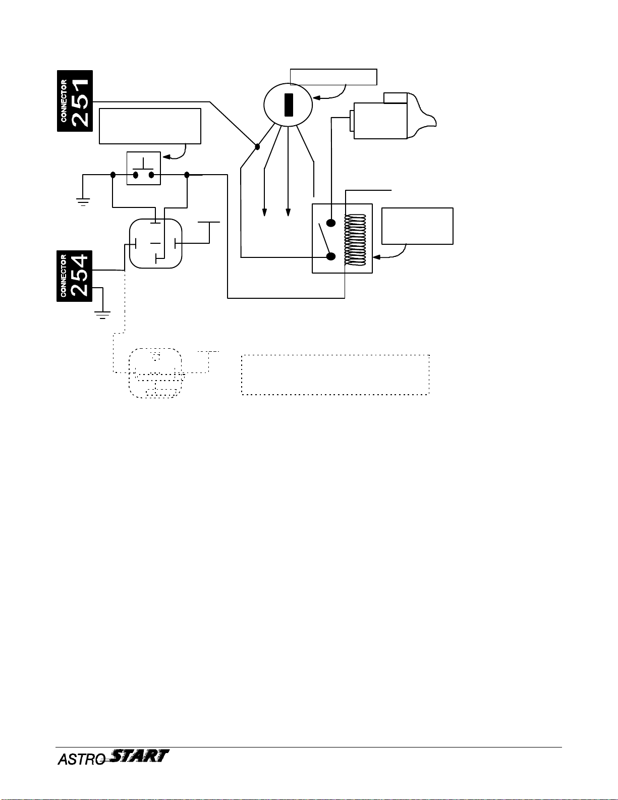
STARTER WIRE SWITCHING .......................................................................................................................................8
STARTER RELAY WIRE SWITCHING...........................................................................................................................9
MAIN HARNESS CONNECTION.................................................................................................................................. 10
MAIN HARNESS TEST.................................................................................................................................................. 11
MAIN HARNESS TROUBLESHOOTING...................................................................................................................... 12
DISABLE SWITCH MOUNTING AND LOCATION ..................................................................................................... 13
INSTALLING THE RECEIVER...................................................................................................................................... 13
MODULE CONNECTION.............................................................................................................................................. 13
SND-1 MODULE INSTALLATION.............................................................................................................................14
HAND BRAKE ............................................................................................................................................................... 14
SENSOR INSTALLATION............................................................................................................................................. 15
RECEIVER INSTALLATION........................................................................................................................................ 15
TRANSMITTER INSTALLATION................................................................................................................................. 16
SENSOR ALIGNMENT................................................................................................................................................ 17
ALIGNMENT VERIFICATION..................................................................................................................................... 18
SYSTEM PROGRAMMING........................................................................................................................................19
PREPARING PRIOR STARTING ................................................................................................................................... 19
MAIN INSTALLATION TEST....................................................................................................................................... 20
TEST AFTER INSTALLATION..................................................................................................................................... 20
MODULE INSTALLATION ........................................................................................................................................... 21
TROUBLESHOOTING ................................................................................................................................................22
START FAIL CODES................................................................................................................................................... 23
RS-504 MODULE........................................................................................................................................................ 23
SND-1 MODULE......................................................................................................................................................... 23
ALARM SYSTEM RS-504............................................................................................................................................ 24
FACTORY DOOR SWITCH INTERFACE ..................................................................................................................... 24
SIREN INSTALLATION ................................................................................................................................................ 25
SHOCK SENSORS.......................................................................................................................................................... 26
INTEGRATED SHOCK SENSOR................................................................................................................................... 26
INTERNAL WARNING BUZZER .................................................................................................................................. 27
ADDITIONAL L.E.D...................................................................................................................................................... 27
OPTIONAL WIRING AND ACCESSORIES...............................................................................................................28
HORN CONNECTION.................................................................................................................................................... 28
REAR WINDOW DEFROSTER ACTIVATION ............................................................................................................. 29
PROTECT INPUT........................................................................................................................................................... 29
DOOR LOCK INTERFACE............................................................................................................................................ 30

PAGE 2193-504-121-00 4L25
SPECIAL APPLICATIONS.......................................................................................................................................... 31
CARBURETED OR THROTTLE ASSISTED VEHICLES.............................................................................................. 31
SECONDARY CIRCUITS............................................................................................................................................... 31
DUAL PARKING LIGHT CIRCUITS ............................................................................................................................. 32
OVERRIDING FACTORY/AFTERMARKET ANTI-TEFTH SYSTEMS ................................................................33
G.M PASS-KEY SYSTEMS............................................................................................................................................ 33
FACTORY & AFTERMARKET ALARM OVERRIDE................................................................................................... 34
STANDARD FACTORY SYSTEM................................................................................................................................. 34
AFTERMARKET ALARMS ........................................................................................................................................... 35
R.A.P SYSTEM (GM VEHICLES).................................................................................................................................. 36
CODE LEARNING OF ADDITIONAL TRANSMITTER..........................................................................................37
REPLACING A LOST TRANSMITTER..................................................................................................................... 37
GLOSSARY...................................................................................................................................................................38
CRANKING CYCLES................................................................................................................................................... 38
CARBURATOR TYPES................................................................................................................................................ 38
VATS AND PASSKEY SYSTEMS.................................................................................................................................. 38
CONTROL MODULE PROGRAMMING...................................................................................................................39
REMOTE CONTROL MODES.................................................................................................................................... 39
ENTERING THE USER PROGRAMMING MODE....................................................................................................... 39
ENTERING THE INSTALLER PROGRAMMING MODE:............................................................................................ 40
ENABLING THE VEHICLE TO RECEIVE INSTRUCTIONS........................................................................................ 40
EXITING THE INSTALLER PROGRAMMING MODE ................................................................................................ 40
RS-504 PROGRAMMING............................................................................................................................................ 41
INSTALLER PROGRAMMING CODES—CONFIDENTIAL......................................................................................... 42
SND-1 MODULE......................................................................................................................................................... 43
USER PROGRAMMING CODES RS-504 .................................................................................................................... 44
RS-504 RESPONSE CODES......................................................................................................................................... 45
CONTROL MODULE.................................................................................................................................................. 45
{SND-1 MODULE.................................................................................................................................................. 45
RS-504 ALARM INFRACTION CODES....................................................................................................................... 45
RS-504 COMMAND CODES........................................................................................................................................ 46
RS-504 REFECENCE CARD........................................................................................................................................ 47
RS-504 WIRING DIAGRAM........................................................................................................................................48
RS-504 WIRING CHART............................................................................................................................................. 48
PART LIST.................................................................................................................................................................... 49

193-504-121-00 4L25 PAGE 3
WARNINGWARNING
ASTROSTART™ RS-504 system is designed for use in all manual shift transmission, gasoline or diesel
powered, fuel injected vehicles.
Carbureted or throttle-assisted vehicles need an optional solenoid kit.(part #310-050-501)
Diesel vehicles need a Diesel Tach Sensor DTS-1 (part #310-066-500).
Do not install in vehicles equipped with a automatic transmission.
VEHICLEPRE-CHECKVEHICLEPRE-CHECK
Prior to installing the unit, go through this checklist carefully:
• Is the starter in good working condition?
• Is the battery fully charged?
• Does the climate control system work properly?
• Are the parking lights and horn functional?
• Are the hand brake, and the “BRAKE” indicator functional?
• Has the ASTROSTART™ switch been set to the OFF position prior to installation?
• Is the power door lock system (if used) working properly (some vehicles do not have a drivers door motor)?
BEFOREYOUBEGINBEFOREYOUBEGIN
Installing the ASTROSTART™ system is a simple step by step process. Take the time to review each step.
For a trouble free installation follow these guidelines:
• Carefully review the installation instructions and wiring diagrams.
• Solder all electrical connections.
• Probe and confirm every connection before soldering.
• Do not try to use the ASTROSTART™ before programming the unit properly.
• Do not cut or splice any of the ground wires. Use ring terminals to ground each wire to the chassis of the
vehicle.
• Probing unknown wires with a test light could damage the vehicles electrical system. To probe safely, use a
voltmeter or the ASTROSTART™ Multitest tool.
• Never disconnect any Air Bag circuits when probing wires at the steering column, serious damage can occur.
VEHICLEPREPARATIONVEHICLEPREPARATION
• You must first prepare the vehicle as follows:
• Leave the drivers door window open and remove the dome light fuse.
• Expose the under dash wiring on the drivers side by removing any panels blocking access.
• Find a suitable location under the dash for the ASTROSTART™ module. Do not locate close to any moving
parts (brake pedal, steering column, gas pedal, etc...).
• Make sure that the transmission shifter is in the “NEUTRAL” position.

PAGE 4193-504-121-00 4L25
SYSTEMINSTALLATIONSYSTEMINSTALLATION
STEP 1
RUNNINGWIRESINTOTHEENGINECOMPARTMENTRUNNINGWIRESINTOTHEENGINECOMPARTMENT
RUNTHEFOLLOWINGWIRESINTOTHEENGINECOMPARTMENT:RUNTHEFOLLOWINGWIRESINTOTHEENGINECOMPARTMENT:
• BLK/RED (harness #253) hood pin switch
• BLK/GRN (harness #252) ignition coil
• Temperature Sensor (harness #411)
WIREROUTINGPROCEDUREWIREROUTINGPROCEDURE
• Locate an existing rubber grommet on the firewall
• Run all wires through this grommet
• After you have made your connections (pin switch, tach, temp sensor) cover wires with split loom wire
conduit and secure using tie straps.
• Make sure that all your wiring is secured away from any moving parts or heat sources.
• Use Silicone to seal up the grommet opening.
• In the event that there is no available grommet in the firewall, carefully drill a hole and insert an appropriate
grommet.
STEP 2
PINSWITCHINSTALLATIONANDWIRINGPINSWITCHINSTALLATIONANDWIRING
HARNESS#253HARNESS#253
The Pin Switch is installed to prevent the vehicle from starting with the hood open. This important SAFETY
precaution prevents the possibility of the engine starting by mistake when the vehicle is being serviced. This
feature will also shut the engine off immediately if someone attempts to open the hood after the vehicle has
been started by remote.
PINSWITCHMOUNTINGPINSWITCHMOUNTING
• The switch must be mounted in contact with the chassis (ground) of the vehicle
• The switch must line up with the hood so that the hood pushes down on the switch (disconnects contact to
chassis of vehicle) when it closes.
• Connect the BLK/RED wire on harness #253 to the pin switch.

193-504-121-00 4L25 PAGE 5
PINSWITCHTESTINGPINSWITCHTESTING
• Close the hood.
• Set your voltage meter to the "Continuity" mode
• Attach one meter probe to the BLK/RED wire, attach the other meter probe to the chassis of the vehicle.
• With the hood closed there should be no indication of continuity to the chassis of the vehicle.
• Open the hood
• With the hood open the meter should indicate continuity to chassis ground.
• If the pin switch does not work exactly as outlined above you will have to readjust.
Caution: Advise your customer of the importance of maintaining this switch in good working
condition. Ask the customer to check switch operation at least once every month. by performing the
following tests;
Ø Start the vehicle by remote control,
Ø Than releasing the hood. The engine should shut off immediately,
Ø If this does not occur the customer should return to your installation facility immediately.
STEP 3
TEMPERATURESENSORINSTALLATIONTEMPERATURESENSORINSTALLATION
HARNESS#411HARNESS#411
The Temperature Sensor monitors the engine temperature at all times. When selected by remote control this
sensor will activate the ASTROSTART™ system when the temperature falls below a certain temperature. The
engine will automatically start and run for ten (10) minutes. This feature is used to maintain engine temperature
in times of extreme cold.
TEMPERATURESENSORMOUNTINGTEMPERATURESENSORMOUNTING
• Locate the engine heater hose (hose that connects to the heater core).
• Place the Temperature Sensor on the hose and secure with "Tie Straps".
5/16”

PAGE 6193-504-121-00 4L25
STEP 4
TACHWIRECONNECTIONTACHWIRECONNECTION
HARNESS#252HARNESS#252
This connection enables the ASTROSTART™ system to monitor engine R.P.M (Revolutions Per Minute). This
information is used to determine when to disengage the vehicles starter motor, and to shut the engine off when
the engine R.P.M becomes too high.
The RS-504 will display the tach pulses after enabling the function via the programming mode.
• 0,0 I1 C,B AND 0,0 U4 C,C
Or using the Multitest module will enable you to read the RPM via a digital readout.
IGNITIONCOILTYPES&CONNECTIONIGNITIONCOILTYPES&CONNECTION
• Refer to the "WIRE CODING SHEET" for vehicle "Tach" wire colour.
• Programming: - Program according to the number of cylinders (" # CYL" Installer Programming Mode).
• 5,1 I1 A,A TO 5,7 I1 C,A
A)STANDARDIGNITIONCOILWITHSEPARATEDISTRIBUTOR
This system incorporates a separate coil and distributor. The "Tach" wire is relatively easy to locate as the coil
itself is labeled with + & -. Connect the BLK/GRN to the NEGATIVE SIDE of the ignition coil.
-
+
BLACK/GREEN
DISTRIBUTOR
RED
IGNITION COIL

193-504-121-00 4L25 PAGE 7
B) THEMULTICOILDISTRIBUTORLESSSYSTEM
The multicoil distributorless system is similar to the one on the diagram below. Two, three or four coils are
located in the same control module with four, six, or eight spark plug wires exiting the module. Connect the
BLK/GRN wire to the PULSE INPUT wire at the module. (Wire that gives a tach signal)
In certain cases, there will be two white wires coming from the module. When tested using the MultiTest, both
wires will have a tach signal. Use the wire where the tach signal appears sooner while cranking the engine.
C)OTHERMULTICOILSYSTEMS
All other multicoil ignition systems have one, two, four or six cylinders per coil and each coil's negative terminal
is available for tach signal. This means that a three coil, six cylinder vehicle has three tach wires each
providing a tach signal for two cylinders. Connect the BLK/GRN wire to one (1) of the ignition coils.
• Program your ASTROSTART™ system to the setting corresponding with the number of cylinders that each
ignition coil services. eg. A three coil, six cylinder vehicle would be set for two (2) cylinders.
STEP 5
BRAKEPEDALCONNECTIONBRAKEPEDALCONNECTION
HARNESS#253HARNESS#253
This connection is made to enable the brake pedal to shut the engine off when started by remote control. This
prevents anyone from driving the vehicle without using the ignition key when it has been remote started.
CONNECTIONCONNECTION
• Locate the brake switch.
• Find the N.O. (Normally Open) brake switch wire (the wire that indicates +12V only when the pedal is
depressed.
• Connect the WHT/GRN wire on harness #253 to this wire.
Note: Some vehicles require the ignition to be ON in order for the brake lights to work. Keep this in
mind when locating the N.O. brake switch wire.
BLACK/GREEN
MULTICOIL DISTRIBUTORLESS IGNITION SYSTEM, TACH SIGNAL

PAGE 8193-504-121-00 4L25
STEP 6
CLUTCHSWITCHOVERRIDINGCLUTCHSWITCHOVERRIDING
In most manual shift transmission vehicle’s, the clutch must be held down to start the vehicle. Your remote
starter must simulate this operation. It is necessary to add a relay that shorts the clutch contacts only when
starting by remote.
WIRINGWIRING
• First, find the clutch switch located on top of the clutch pedal.
• Determine witch type of switching is used.
• Make connections according to the corresponding diagram below.
Following are the two types of switching most frequently used by vehicle manufacturers.
The clutch switch is used as a normally open contact to disable the starter by :
• Type # 1: cutting the starter circuit from ignition (see diagram # 1).
• Type # 2: cutting the wire that controls the starter relay from ground (see diagram # 2).
Never use a jumper to by-pass the clutch switch.
The clutch switch is the main security device featured by the manufacturer.
By-passing this switch could result in injuries to the user or its environment.
STARTERWIRESWITCHING
This type of circuit allows to connect the DK BLUE wire from harness #251 directly to the starter supply wire.
DIAGRAM # 1
STARTER
IGNITION KEY
CLUTCH PEDAL
SWITCH
DARK BLUE
LARGE GAGE WIRE
THAT SHOWS
+12VDC WHEN THE
KEY IS THE START
POSITION AND THE
CLUTCH PEDAL IS
PRESSED

193-504-121-00 4L25 PAGE 9
STARTERRELAYWIRESWITCHING
DIAGRAM # 2
If the special application is used for something else. It is possible to double this output , using a relay in parallel.
See diagram # 2 (dashed lines).
PROGRAMMING
The factory setting for this output is;
•• 6,1 IGNIT I2 A,A
When this output is doubled (see dashed lines in the previous diagram) the possible programming settings are;
• 6,1 IGNIT I2 A,A
• 6,3 CARB UNIV I2 A,C
• 6,4 CARB T.B.I I2 B,A
• 6,7 VATS I2 C,A
• 6,8 VATS 6s I2 C,B
• 6,9 VATS 1.5m I2 C,C
• 6,10 VATS 3.m I2 A
• 6,11 VATS 5m I2 B
CLUTCH PEDAL
SWITCH
STARTER
RELAY
IGNITION KEY
DARK BLUE
+12vdc
STARTER
87
86 87A 85
30
87
86 87A 85
30
BLACK
BROWN
2 ND relay for special applications.
Eg: alarm overriding,
carburetor solenoid, etc....
+12vdc
+12vdc

PAGE 10 193-504-121-00 4L25
STEP 7
MAINHARNESSCONNECTIONMAINHARNESSCONNECTION
HARNESS#251HARNESS#251
Begin by locating the main IGNITION circuit of the vehicle. This factory harness is located behind the
IGNITION key of the vehicle. These wires are usually the largest gauge wires under the dash and are
easy to find. SOLDER ALL CONNECTIONS.
RED - Main Battery Power (+12V Input)
Locate the largest gauge +12V power source at the IGNITION key harness. Solder the RED wire to
this circuit. This is the main power supply to the ASTROSTART™.
ORG - Ignition Output (+12V Output before, during, and after cranking)
Locate the largest gauge wire that shows +12V when the key is in both the RUN and START
positions.♣Solder the ORG wire to this circuit. The ORG wire supplies +12V to the ignition circuit
four (4) seconds before cranking and while the engine runs by remote.
DK/BLU - Start Wire (+12V Output while engine is cranking only)
Locate the largest gauge wire that shows +12V ONLY when the engine is cranking. ♣Solder the
DK/BLUE wire directly to this circuit. The DK/BLU wire provides +12V to the starter solenoid, this
activates the starter motor.
If the starter wire passes through the clutch switch contacts, connect this wire to the contact that goes directly to the
starter. See step 5, diagram # 1.
YEL - Heater/AC Control (+12V Output before & after starting)
Locate the largest gauge wire that shows +12V when the key is in the RUN or ACC position ONLY. ♣
Solder the YEL wire to this circuit. The YEL wire provides power to the Heater and Air Conditioning
systems.
BLK - System Ground Input.
This is the main ground connection and of the upmost importance to ensure reliable system operation.
Always attach the ring terminal to the vehicle's chassis behind the driver's side kick panel.
NEVER CONNECT THIS GROUND WIRE TO THE DASHBOARD.
♣Note: If you find more than one of these wires in the IGNITION key harness you may have to
interface a second circuit. See the “Special Applications”section on page 31.
GRN - Parking Light Interface (+12V Output)
This interface enables parking light acknowledgement of system operation. Locate the wire at the back
of the vehicle light switch that is live when the parking lights are operational. Connect the GRN wire to
this circuit.
Note: If the vehicle uses a negative switched signal at the master light switch it may be necessary to
connect directly at one of the parking light bulbs either at the front or rear of the vehicle.

193-504-121-00 4L25 PAGE 11
PRIOR TO PROCEEDING WITH THIS STEP,
MAKE SURE THAT
THE TRANSMISSION SHIFTER IS IN THE NEUTRAL POSITION,
THE HAND BRAKE IS FUNCTIONAL AND PROPERLY APPLIED.
STEP 8
MAINHARNESSTESTMAINHARNESSTEST
Once you have made all the necessary connections to harness #251, you are ready to proceed with a quick test
of these circuits. Using a split jumper make the following connections as illustrated in the diagram.
1) Ignition Test - Connect the RED and ORG wires using the jumper. Leave the jumper in this position until all
the tests are completed.The dash board should light up.
2) Start Test - MOMENTARILY connect the jumper to the DK/BLU wire. This connection will engage the starter
motor. When performing this test, make sure that you remove the jumper from the DK/BLU wire the instant
that the engine starts up. Leaving this wire connected will damage the starter motor.
3) Heating/AC Test - Connect the RED and YEL wires using the jumper. This connection will engage the
climate controls of the vehicle. Test all climate control functions for proper use.
4) Parking Lights Test - Connect the RED and GRN wires using the jumper. This connection will engage the
parking lights.
5 ) Totally Disconnect The Jumper - All functions should stop operating.
RED RED RED RED
ORANGE BLUE YELLOW GREEN
MALE TERMINAL
1
2
3
4

PAGE 12 193-504-121-00 4L25
MAINHARNESSTROUBLESHOOTINGMAINHARNESSTROUBLESHOOTING
ENGINEDOESNOTCRANKS:
• You may have connected to the wrong starter circuit.
• The vehicle may require a second starter circuit.♠
• DK BLU wire may be damaged, or not connected correctly.
ENGINECRANKSBUTWILLNOTSTART:
• You may have connected to the wrong ignition circuit.
• The vehicle may require a second ignition circuit.♠
• ORG wire may be damaged, or not connected correctly.
DIGITALDASHDOESNOTILLUMINATE:
• The vehicle may require a second ignition circuit. ♠
HEATERORA/CDOESNOTFUNCTIONWHENSTARTEDBYREMOTE:
• You may have connected to the wrong accessory circuit.
• YEL wire may be damaged, or not connected correctly
• The vehicle may require a second accessory circuit. ♠
ONLYLEFTSIDEORRIGHTSIDEPARKLIGHTFUNCTION:
• Vehicle has split lighting circuit. ♠
PARKLIGHTSDONOTFUNCTION:
• You may have connected to the wrong parking light circuit.
♠See “Specials Applications” section on page 31 for information.

193-504-121-00 4L25 PAGE 13
STEP 9
DISABLESWITCHMOUNTINGANDLOCATIONDISABLESWITCHMOUNTINGANDLOCATION
HARNESS#401HARNESS#401
• The ASTROSTART™ disable switch is used to interrupt or
disable system operation. Mount this switch where it is
easily accessible to the drivers seat.
• Connect it to the SND-1 module’s connector “B”.
Note: Door lock/unlock and Alarm functions are not
affected by this switch.
STEP 10
INSTALLINGTHERECEIVERINSTALLINGTHERECEIVER
The receiver's installation is critical to ensure maximum range. Mount it behind the windshield's rear view
mirror, precisely in the middle of the glass and about 3" to 4" from the top. Run the wire behind the vehicle's
trim molding to the control module.
NOTE: Vehicles with electrically heated windshields (ie. Lincoln, Ford Taurus), or with special solar
windshields (ie. Lumina APV vans) will require an alternate mounting location for the antenna. In the
case of a vehicle with a fiberglass roof, the antenna can be positioned inside the headliner. For
vehicles where the roof is steel, attach the antenna to the back window using the optional 14 foot cable
extension. (see parts list for part number)
STEP 11
MODULECONNECTIONMODULECONNECTION
Once all connections are done with the exception of the harness ”R”’s GREEN wire of the SND-1 module,
connect all harness to the main and SND-1 modules, then depress the brake pedal. Do not mount the module
until all programming and testing are completed.
CONNECTIONS ARE:
SND-1 MODULE
Ø DL-3 HARNESS NO CONNECTION.
Ø 002 HARNESS COMMUNICATION CABLE TO THE MAIN MODULE, CONNECTOR 002.
Ø “A” HARNESS INTERUPTS OUTPUT TO MAIN MODULE CONNECTOR “401”
(HARNESS 401-A).
Ø “B” HARNESS MAIN SWITCH (HARNESS 401).
Ø “E” HARNESS INFRARED TRANSMITTERS.
Ø “R” HARNESS INFRARED RECEIVERS.
MAIN MODULE
Ø 001 HARNESS DL-3 MODULE (IF USED).
Ø 002 HARNESS COMMUNICATION CABLE TO THE SND-1 MODULE, CONNECTOR 002.
Ø 252 HARNESS TACH INPUT.
Ø 253 HARNESS INTERRUPT.
Ø 254 HARNESS SPÉCIAL APPLICATIONS (IF USED).
Ø 255 HARNESS SIREN AND HORN OUTPUT.
Ø 256 HARNESS DOME INPUT.
Ø 257 HARNESS R.F. RECEIVER.
Ø 261 HARNESS SUPPLÉMENTARY DÉTECTORS.
Ø 401 HARNESS INTERRUPT INPUT FROM SND-1 MODULE CONNECTEUR “A”
(HARNESS 401-A).
Ø 411 HARNESS TEMPÉRATURE.SENSORS
Ø 251 HARNESS MAIN HARNESS (CONNECT THIS HARNESS AFTER ALL THE OTHERS)
O
F
FO
N

PAGE 14 193-504-121-00 4L25
STEP 12
SND-1MODULEINSTALLATIONSND-1MODULEINSTALLATION
HANDBRAKEHANDBRAKE
This connection monitors the hand brake status. It disables the system when the hand brake is not applied or
released.
Most vehicle’s hand brake monitoring circuits use negative switching. (ground when hand brake is applied).
To avoid any ground feed-back from the vehicle’s circuitry, you must add a diode in the circuit following the
diagram below.
Ø Cut the hand brake wire.
Ø Solder the negative side ( side marked with a white trace) of the diode (1N4004) to this wire toward the hand
brake switch.
Ø Solder the positive side of the diode to this wire toward the “BRAKE” indicator.
Ø Solder the GREEN wire of harness “R” at the hand brake switch.
For positive switching circuits, solder the diode in the opposite way (negative terminal toward the
“BRAKE” indicator). For programming positive switching detection refer to “SND-1 MODULE” in
the “PROGRAMMING” section on page 43.
P
SND-1
R
GREEN
HAND BRAKE INDICATORS

193-504-121-00 4L25 PAGE 15
SENSORINSTALLATIONSENSORINSTALLATION
RECEIVERINSTALLATIONRECEIVERINSTALLATION
HARNESS“R”ONTHESND-1MODULE
Ø Disassemble the center console surrounding the transmission shifter, and the hand brake lever.
Ø Locate two suitable location on the floor, close to the transmission shifter, where it will be possible to fasten
the two receivers (fig. A). Do not install both sensors on the same angle(fig. B.).
FIGURE A FIGURE B
Ø Then locate on the transmission shifter, in the “NEUTRAL” position, the lowest location where the
transmitters will be installed. (Visual contact must be possible with the receivers installed on the floor.)
Ø Make sure that the chosen location will not disturb the shifter dust boot. A constant friction on the boot will
cause damage to it, or alter the adjustment of the sensors.

PAGE 16 193-504-121-00 4L25
Ø Once you have determined the location where all the components will be installed, you may continue with
assembling the fixture.
Ø Refer to the following diagram to assemble the two receivers on their fixture.
Ø Then fasten both receivers at the base of the transmission shifter on the pre-selected location, making sure
that visual contact with the transmitters will be possible once installed.
Note: Use only one screw on the fixtures, this gives you the possibility to rotate the fixtures during final
adjustments .
TRANSMITTERINSTALLATIONTRANSMITTERINSTALLATION
HARNESS“E”
Refer to the following diagram to assemble the two transmitters on their fixture.
When both transmitters are mounted, you may fix it temporarily using the two sided tape (included in the kit)
then continue with the alignments. The sensors are matched in pairs, these pairs are identified by their wire
colors. E.g.: The transmitter with the BLACK/WHITE wires matches with the receiver with the BLACK/WHITE
wires. When installing the sensors make sure that the pairs are matched.
Note: The two sided tape supplied takes approximately 48 hours to get its full strength. You have plenty
of time to complete the alignments.

193-504-121-00 4L25 PAGE 17
SENSORALIGNMENTSENSORALIGNMENT
A perfect alignment of the sensors is extremely important. There are different ways to do so at your disposal:
ALIGNMENT USING THE L.E.D.
Ø The SND-1 module has two LEDs to adjust the sensor’s position. One per sensor pair.
Ø When DIP # 1 on the SND-1 module is in the “ON” position and the brake pedal is depressed, the module
goes into the adjustment mode.
Ø The module generates two beeps each time the brake pedal is released to indicate that the module is in the
adjustment mode.
Ø When in this mode, a LED will light up when the corresponding sensor pair is aligned.
Ø When the shifter is in the “NEUTRAL” position, put DIP # 1 in the “ON” position, depress the brake pedal,
then align the receivers and transmitters in order to light up both LEDs.
Ø Remember that it is impossible to remote start the engine when the SND-1 module’s DIP # 1 is in the “ON”
position.
FIGURE A FIGURE B
ALIGNMENT USING THE SPECIAL TOOL
Ø A tool has been especially designed to help the installers in aligning the sensors.(fig b.)
Ø This tool holds the sensors in place while fastening them.

PAGE 18 193-504-121-00 4L25
ALIGNMENT VERIFICATION
Ø When every adjustment is made, put the tie wraps in place around the transmitter fixtures, and thigh lightly.
Ø Check when slightly moving the shifter in every direction that at least one LED shuts off.
Ø Check that both LED’s shuts off when the transmission shifter is in gear. See diagram below.
Ø Also make sure that the sensors cannot affect the shifter movement when this one is moved in all directions.
If so, relocate the sensors.
Ø TPut DIP # 2 in the “ON” position and check if both LEDs still light up when the shifter is in the “NEUTRAL”
position. Realign the sensors if necessary.
Ø START the engine with the key , and check if both LEDs remain lit while the engine is cranking. This
procedure is to ensure that when starting the engine, the shifter lever will not move significantly enough to
produce a START fail condition to the remote starter. If any LEDs go out during this test, relocate the
sensors to correct this situation.
Ø When all the sensors are aligned properly, you can tighten up the tie wraps around the transmitter fixtures.
Ø We recommend to apply glue (Lock-Tite or Crazy-glue) on every screw surface, then tighten mildly.
Ø Fasten the harness’ to the shifter by putting the tie wraps on the gray sleeve, not on the sensor wires. Leave
some leeway on the harness at the base of the shifter to avoid pulling on it when the shifter is moved.
Ø Fasten the harness’ to the floor, away from any mobile parts.
Put DIP # 1 and # 2 of the SND-1 module to the “OFF” position.
TIt is of the most importance that this test be done. When DIP # 2 is “ON”, it simulates a temperature of -30º C
that reduces the sensor's sensitivity. If this test is omitted, the remote starter might not work on very cold
weather.
Zones
where
BOTH
L.E.D.s
must be
OFF
Zone
where
at least ONE
L.E.D.
must be
OFF
Zone
where
BOTH
L.E.D.s
must be
ON

193-504-121-00 4L25 PAGE 19
STEP 13
SYSTEMPROGRAMMINGSYSTEMPROGRAMMING
The following section outlines "Basic Starter Installation Programming". All ASTROSTART™ models require
certain vehicle, and system configuration parameters to be entered prior to testing the system.
PROGRAMMINGPROCEDURES:
• Turn to the " Installer Programming" section on page 42.
• After the programming is done continue on next page.
PREPARINGPRIORSTARTINGPREPARINGPRIORSTARTING
The remote starter must have received a confirmation from the SND-1 module to be ready for starting.
The SND-1 module sends this confirmation by way of an audio signal (beep) each time the BRAKE pedal is
depressed without the key in the ignition switch, or each time the ignition key is turned from the “RUN” to the
“OFF” position.
Press the BRAKE pedal to generate a confirmation code from the module.
CONFIRMATION
1 beep The system is ready to receive a START command.
2 beeps System not ready. The shifter is out of the “NEUTRAL” position.
3 beeps System not ready. The hand BRAKE is not applied properly.
4 beeps System not ready. The security sequence was not recognized. T
5 beeps Harness “A” is not connected to the SND-1 module, or harness “401-A” is not
connected to the RS-504 module.
TThis sequence is part of the security features of the SND-1 module, it monitors the position of the
transmission shifter at all times.
This sequence is validated each time the transmission shifter is moved from the “IN GEAR “position to the
“NEUTRAL” position when the hand BRAKE is not applied.
If the system sends a code 4 (4 BEEPS) you must:
• release the hand brake;
• put the shifter in gear (any position);
• bring the shifter back to the “NEUTRAL” position;
• apply the hand brake;
• press the brake pedal to generate a confirmation code.
Table of contents
Other AstroStart Remote Control manuals