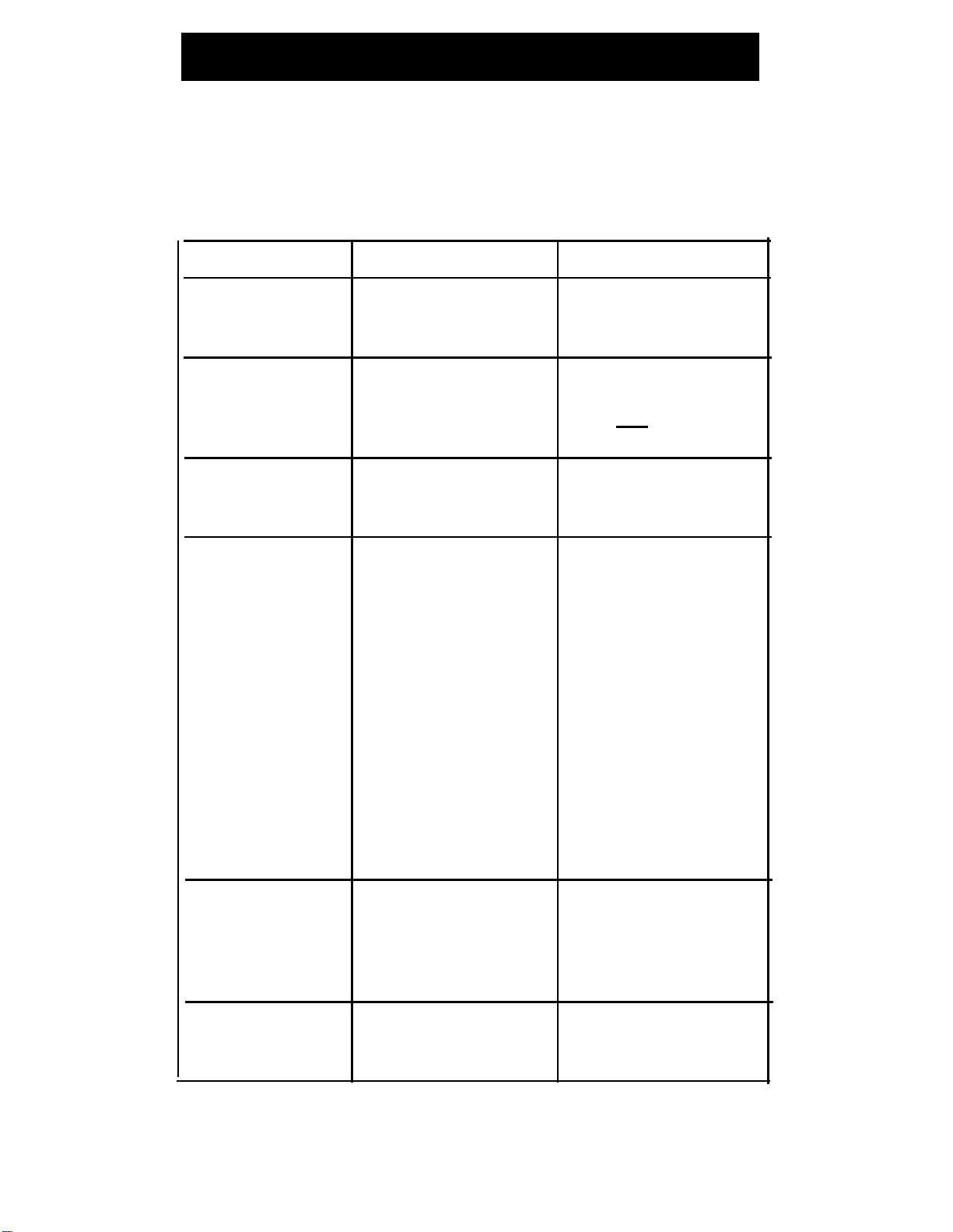
AT&T MDC 9000 User manual

AT&T
MDC 9000 Cordless
Business Telephone
Quick Reference
Contents
Handset Controls
1
Handset Display 2
Line Status Indicators 2
Base Controls 3
Base Connectors 4
Troubleshooting 5-6
MDC 9000 Compatibility 7-12
Personal Directory back cover
Remember to press the [On/Off] button to turn on your cordless
phone, before pressing any other button.
Help!
For more information, see the MDC 9000 Cordless Business
Telephone Installation booklet. If you need assistance, call the
AT&T Helpline at 1 800 628-2888.
AT&T 503-801-100 Issue 1 (May 1994)
Comcode 107169047
Copyright
©
1994 AT&T
AT&T

Handset Controls
Headset On/Off
Button
Press to turn the
User
Instructions
headset on and off.
Provides reference
information for most
common cordless phone
features.
Antenna
Headset Jack
Insert adapter
cord when using
a headset.
Directory Card
Handset Display
Displays status of
lines and range.
For detailed descrip-
tion, see "Handset
Diplay" on page 2.
Press to transfer
a call to another
extension.
Extension Label
Outside Line/
Earpiece
Volume
Control Switch
Slide switch to adjust
volume of earpiece.
Two positions:
Normal
and
High.
Status
Press to turn on
display when
handset is off, or to
update display when
STAT
indicator
appears.
On/Off
Press to turn the
handset on.
ON
appears in handset
display. To turn off,
press again. Turn on
to make or answer
a call, and turn off
to “hang up.”
Conf
(Conference)
Press to conference
in (add) another
party to your call.
(Behind cover)
Battery Charging
Contacts
Handset battery
charges through
these contacts.
Programmable/
Intercom/Drop
Buttons (6)
See “MDC 9000
Compatibility” on
page 7 for system
button assignments.
HoId
Press to put a call
on hold.
Feat
(Feature)
Press to enter
programming mode
or to use dial-code
features. Not used
on System 25,
System 75, System
85, or DEFINITY
®
system.
Trans
(Transfer)
Write the extension
number on this label
using a pencil or
ball-point pen only.
1

Handset Display
➀
➁
➂
Line Status Indicators See below.
➃
➄
P appears when in programming mode.
STAT appears when handset is out of range. Remains until
all line status indicators are updated.
MSG appears when message LED lights on base.
BATT indicates low battery voltage. Handset also emits 4
short beeps. Place handset on base to recharge.
RANGE indicates handset is out of range when [On/Off] or
[Status] (off only) is pressed. Handset also emits 2 beeps. To
make or receive calls, move handset closer to the base.
ON indicates handset has been turned on by pressing [On/Off] .
➅
➆
Line Status Indicators
There are six line status indicators. Each indicator corresponds
to a specific outside line/programmable/intercom/drop button.
The indicators show either a triangle of a rectangle, signifying
activity as follows:
PARTNER Systems
Arrow ( ▲ or ▼ ) indicates activity at YOUR extension.
Rectangle () indicates activity at ANOTHER extension.
All Other Systems:
Rectangle () indicates activity at YOUR extension.
Arrow ( ▲ or ▼ ) indicates activity at ANOTHER extension.
2

Base Controls
Handset Hook
Rotate for wall
mounting.
Battery Charging
Talk LED
Contacts
Lights when handset
The handset battery
is removed from base
charges through
and switched ON.
these contacts.
Antenna
Base Extension
Label
Ringer Volume
Controls
Write this phone's
extension number
on this label using a
pencil or ball-point
pen only.
Base Ringer
Rings when a call
comes in. Adjust
volume or turn ringer
off using the Ringer
Volume Controls.
Message LED
Press appropriate but-
ton to adjust base's
Charge LED
ringing volume. Base
ringer turns off at bot-
tom of range (unless
handset is on the base).
When the handset is on
the base, only the base
rings. When the hand-
set is off the base, both
base and handset ring.
Lights when handset
is placed properly on
base and battery is
charging.
3

Base Connectors
Power Cord
Channel
TeIephone Line
Cord Channel
Desk mounting only. Desk mounting only.
Power Cord
Mounting Stand
Slot
For attachment of the
mounting stand.
Channel
Power Cord
Jack
Power cord is
inserted here.
Wall mounting only.
Mounting Stand
Slot
Telephone Line
Cord Jack
Telephone line cord
is inserted here.
For attachment of
the mounting stand.
4

Troubleshooting
If you have a problem with your cordless phone, you may be
able to solve it by following the procedures listed here. If you
cannot resolve a problem using these procedures, call the
AT&T Helpline at 1 800 628-2888, 24 hours a day.
Symptom
Possible Causes Possible Causes
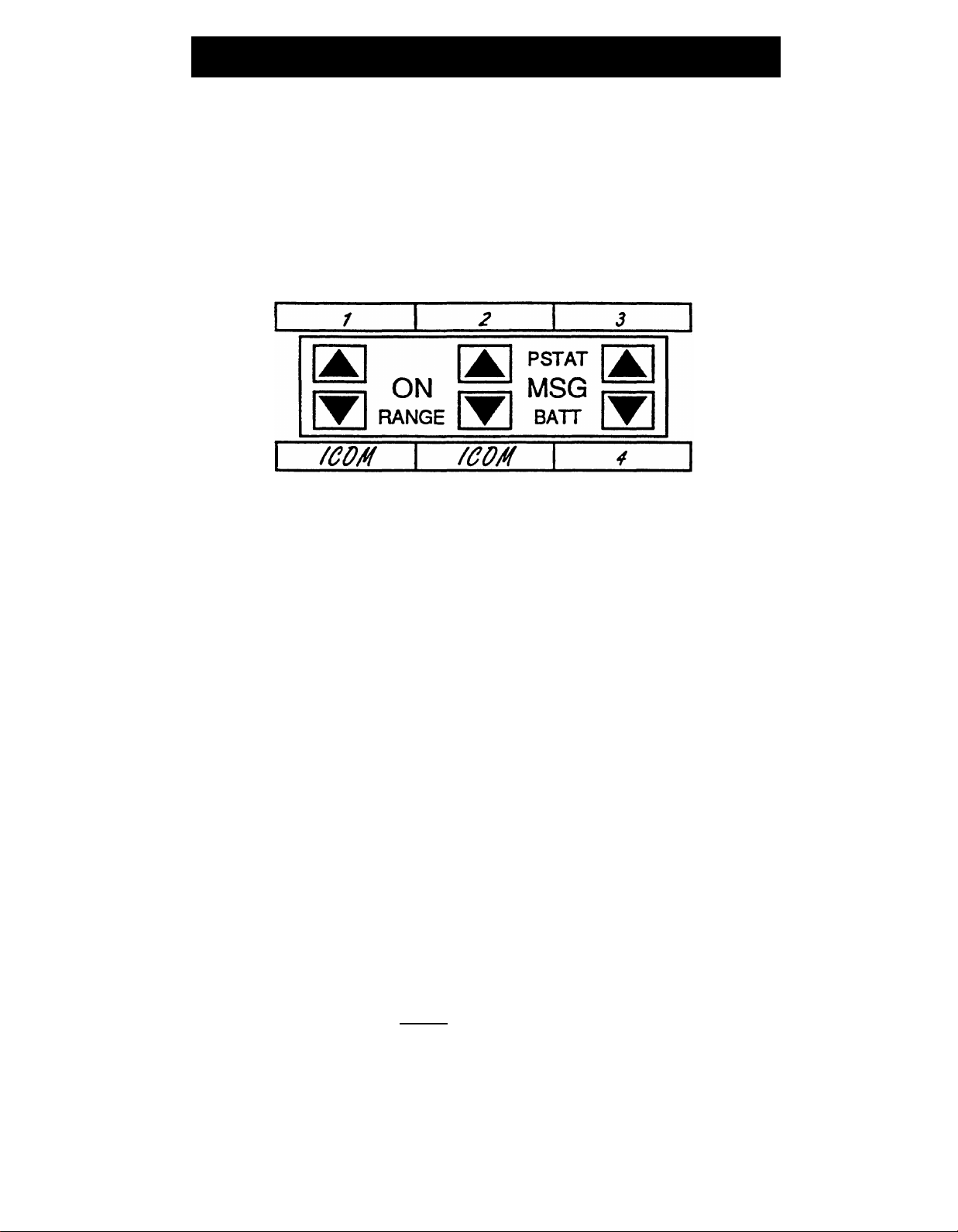
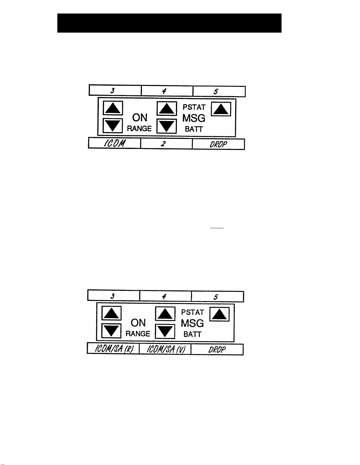
RANGE
indicator Handset is out of range of Move closer to the base.
appears on the
the base.
handset display.
STAT
indicator
Handset is too far from the Move closer to the base;
appears on the base for display to be or
handset display. updated automatically. Press
[Status]
to update
indicators on display.
BATT
indicator Battery pack power is low.
Recharge battery pack
appears on the by placing the handset on
handset display. the base.
Range for calls is
Something in the area may
Relocate base to see if
lower than expected. be interfering with your
the range improves (see
radio transmissions (for
“Positioning the Base" in
example, metal reinforced
the Installation booklet)
ceilings, brick walls; or
or
personal computers,
Turn off or unplug nearby
facsimile machines).
equipment (for example,
computer, modem) to see if
it is causing interference. If
it is, make sure it is on a
different power line or
relocate it further from the
base, if possible.
Headset use is limiting the Move closer to the base or
range. use the handset.
Background noise
Radio Frequency Move base to higher
occurs while on a call.
Interference.
location
or
Move base a few feet to the
side, front or back.
Battery pack goes
Power outage or base is Plug base into an outlet not
dead when handset unplugged. controlled by a switch.
is in base.
5

Troubleshooting
Symptom Possible Causes
Possible causes
No ring on incoming Handset is out of range of
Move closer to the base.
call, or handset
the base.
makes hissing
sounds.
Base antenna is not in
Rotate antenna on base
upright position. into upright position.
If you have more than one Place correct handset in
MDC 9000 phone, wrong
base for at least 10 seconds.
handset is placed in the
base.
System is programmed Reprogram extension so
so line does not ring at
the line rings (see system
extension.
documentation).
Base makes clicking There is an open connec- Check the wiring and
sounds.
tion between the base unit
modular connections.
and the connecting switch.
Charge LED does Battery contacts need to Rub battery contacts lightly
not light when hand-
be cleaned.
with a soft eraser. Be sure
set is in base. battery contacts on handset
touch contacts on base.
Base not powered. Plug base into an outlet not
controlled by a switch.
Charge LED flashes
No battery pack or defective Remove battery pack, then
when handset is in
battery pack in handset. reinsert it. If problem recurs,
base. replace battery pack.
Handset does not
Recent occurence of
Remove handset from base
respond to repeated
lightning or strong then replace for 10 seconds;
button presses. electrical interference.
or
Unplug base from AC
wall outlet for one minute,
plug back into outlet, and
place handset on base for
10 seconds;
or
Unplug line cord from
base for one minute, then
reconnect it;
or
Remove handset battery for
one minute, replace, then
place handset on base for
10 seconds.
6

MDC 9000 Compatibility
PARTNER® systems: the MLC-6 Cordless Telephone; the
MERLIN®, MERLIN plus, and MERLIN II systems: a
MERLIN LEGEND® systems: a 10-button ATL set.
System 25: a 10-button set.
System 75, System 85, and DEFINITY systems: a 7303s set.
Your cordless phone is compatible with the phone systems
listed below. To use your phone, follow the programming and
call handling instructions that come with your phone system,
or the specific phone identified below.
■MDC 9000 is fully compatible with the PARTNER
family of phone systems.
■
5-button phone.
■
■
■
Carefully note the functional differences between your cordless
phone and the one identified above, as described in the
foIlowing sections.
Entering Station Programming Mode
■ To enter programming mode, turn the handset on, then
press [Feat] followed by [0] [0] .
■ To exit programming mode, press [Feat] followed by [0] [0]
or turn the handset off.
NOTE:
The above instructions do not apply on System 25, System 75,
System 85, and DEFINITY systems. On those systems, program-
ing buttons are assigned by your system administrator.
PARTNER, MERLIN, MERLIN LEGEND and DEFINITY are registered trademarks
of AT&T
7

MDC 9000 Compatibility
Programming System Features
PARTNER Systems:
■ PARTNER II and PARTNER Plus system buttons should be
assigned as follows; 1, 2, 3, and 4 are line or feature buttons
(for a PARTNER system, buttons 1 through 4 are line only):
MERLIN Systems:
■
■
■
■
■
■
It is recommended that you use MERLIN 206/410/820
systems installed with Feature Package 2 with your
cordless phone.
You must disable the Voice Announce feature. This phone
does not have a speaker function.
You should not be assigned to a paging group.
To program the Ringing Option feature, use the “arrow” and
“rectangle” indicators in the display as the equivalent of red
and green LEDs, respectively.
For MERLIN II system users, if you program an Auto Intercom
button, idle line preference must be set to intercom.
If any of your incoming lines has the call waiting feature,
program the Recall feature on one of the programmable
buttons and press it before you pick up a waiting call. You
can dial #50 before you pick up a waiting call on the follow-
ing: MERLIN 206/410/820 systems only with Feature Package
2, and all MERLIN Plus, MERLIN II and MERLIN 1030/3070
systems. Pressing [On/Off] will disconnect the call.
8

MDC 9000 Compatibility
■ MERLIN 206/410/820 systems and MERLIN Plus system
buttons should be assigned as follows; 2, 3, 4, and 5 are
line or feature buttons:
■ To use MERLIN LEGEND feature codes with this phone,
program the top right-hand button as a System Feature
button. This will permit you to use the wide array of
LEGEND system features by turning the set on, pressing
the System Feature button, and dialing the appropriate
"*" code number. Your cordless phone’s [Feat] button only
allows you to enter programming mode. It does not work
when using the MERLIN LEGEND system features.
■ MERLIN 1030/3070, MERLIN II, and MERLIN LEGEND
system buttons should be assigned as follows; 3, 4, and
5 are line or feature buttons:
9

MDC 9000 Compatibility
System 25:
■ For Releases 1, 2, and 3, this phone must be administered as
a 10-button MERLIN set (type 303).
■ Assigning features may be done only by the system
administrator.
■ Use the following features with caution:
Automatic Intercom, Bridging, Coverage, Direct Station
Selection, Personal Line, Pooled Facility, Send All Calls
(use with single ring reminder).
Since these features provide visual indication that the
feature is on, be aware that if you turn off the handset when
using that feature, you may forget that the feature is on.
■ Do not assign the following features: Auto Answer, Scroll,
Inspect, Directory, Next, Local, Call, and Manual Callback
Queuing.
■ If programming the Flex DSS or Repertory Dial feature, dial
the number to be recorded and push the button you are
assigning to the feature. You will receive 3 short beeps and
a dial tone to confirm programming.
■ If you are programming numbers for the Station Speed Dial
feature, dial the numbers to be stored then dial the Per-
sonal Speed Dialing code (#20 through #39), including the
#. Listen for a confirmation tone followed by a dial tone.
■ System 25 buttons should be assigned as follows; 7, 8, 9,
10, and 11 are system access or feature buttons:
10

MDC 9000 Compatibility
System 75, System 85, and DEFINITY Systems:
This phone must be administered as a 7303s Hybrid terminal for
the following systems:
■ System 75 - R1V1, R1V2, and R1V3
■ System 85 - R2V1, R2V2, R2V3, and R2V4
■ DEFINITY G1 - (R1V4)
■ DEFINITY G2 - G2.1 and G2.2 - (R2V5, R2V6)
■ DEFINITY G3 Version 1 - (R1V5)
■ DEFINITY G3 Version 1.1 and Version 2 - (D92)
■ DEFINITY G3 Version 3 - (D93)
Native terminal administration will be provided in DEFINITY G3
Version 3.
On the older switch types that do not accommodate Universal
modules (System 85 - R2V1, R2V2, R2V3, and R2V4), an ANN17B
Hybrid pack in conjunction with a DS-1 carrier must be used to
connect the switch and this phone. On the newer switches that
accommodate Universal modules:
■ System 75 R1V1, R1V2, and R1V3
■ DEFINITY G1 - (R1V4)
■ DEFINITY G3 Version 1 - (R1V5)
■ DEFINITY G3 Version 1.1 and Version 2 - (D92)
■ DEFINITY G3 Version 3 - (D93)
A TN762B Hybrid pack must be used with the Universal carrier
for this purpose. Note that depending upon the actual hardware
configuration, DEFINITY G2 - G2.1 and G2.2 may utilize either
an ANN17B or TN762B pack. In either case, the latest vintage
packs are recommended.
11

MDC 9000 Compatibility
When using DEFINITY G2.1 and G2.2, General Terminal Admin-
istration (GTA) maybe used to set up “custom” set types so that
administration may be done using that custom set type.
Set administration and button feature assignment may be done
only by the system administrator. It is recommended not to use
a feature that requires visuals (LCD feature icon) to be updated
while the set is off. Also, since some features, such as Send All
Calls, provide visual indication that the feature is on, be aware
that if you turn off the handset when using that feature, you may
forget that the feature is on.
■ System 75, System 85, DEFINITY G1, G2, and G3 system
buttons should be assigned as follows; 1, 2, 3, 4, and 5 are
line or feature buttons:
12

Notes
13

Notes
14

Personal Directory
Record your phone numbers below, in pencil. Insert a System
Speed Dial Code if appropriate.
DIAL
CODE
NAME
PHONE NUMBER
AT&T MDC 9000 Cordless Telephone
-
-
-
~·
--
Other manuals for MDC 9000
1
Table of contents
Other AT&T Cordless Telephone manuals