ATD Tools ATD-WB User manual

ATD-WB
Wheel Balancer
Installation and Operation Manual
Features:
/DUJH5LP'LDPHWHU%DODQFLQJXSWR5LPGLDPHWHURYHUDOO:KHHO'LDPHWHU
/('WRXFKSDQHO.H\SDGZLWKHDV\WRUHDGLFRQV
0XOWL0RGH9HKLFOH%DODQFLQJIRU&DU0RWRUF\FOH
0DQXDO0HDVXUHPHQW,QSXWIRU'LVWDQFH'LDPHWHU
6WDWLF'\QDPLF$/8EDODQFLQJPHWKRGV
6HOI&DOLEUDWLQJ6HOI'LDJQRVWLF
0XOWL8VHU2SHUDWLRQ
,QWHJUDWHG&HQWHULQJ6SULQJIRU%DODQFLQJ6KDIW
3HJVIRU$FFHVVRULHV
,QFOXGHG+RRG+DPPHU&DOLSHU&RQH6HWVVPDOOPHGLXPODUJHH[WUDODUJH
%RZO&ODPSV&DOLEUDWLRQ:HLJKW/DUJH,QGLFDWRU6SHHG1XW
$7':%BUHYB

CONTENTS
1 IntroducƟon P 3
2 Intended Use P 3
3 General Safety Rules P 3
3.1 Safety Devices P 4
4 Transport and Handling P 4
5 Unpacking P 5
6 InstallaƟon and Commissioning P 5
6.1 Electrical ConnecƟon P 5
7 InstallaƟon P 6
8
9
Use Suspension
Environmental InformaƟon
P
P
7
7
10
11
Ordinary Maintenance
ConĮguraƟon
P
P
8
9
12
13
Display Panel & Control Panel
MounƟng the Wheel
13.1 Wheel PosiƟve PosiƟon
13.2 Wheel NegaƟve PosiƟon
13.3 Flange Disc PosiƟoning (OpƟonal)
P
P
P
P
P
10
12
12
12
13
14
Input Machine Three Parameters
14.1 Input DIS (Distance) Value
14.2 Input BR ( Rim Breadth) Value
14.3 Input DIA (Diameter) Value
P
P
P
P
13
13
13
13
15 Unit Conversion BuƩon P 14
16 Start BuƩon P 14
17 Display Imbalance Value P 14
18 Residual Imbalance Value Display P 15
19 Balance Mode SelecƟon P 15
20 Program FuncƟon IntroducƟons P 16
21 Factory Seƫngs P 17
22 Factory CalibraƟon P 18
23 Appendix P 19
23.1 Appendix 1 Layout of Power Supply Board P 19
23.2 Appendix 2 Wiring Diagram P 20
23.3. Appendix 3 ProtecƟon Cover InstallaƟon P 21
24 Fire ProtecƟon Equipment to be Used P 22
25 Error IndicaƟon P 22
Limited Warranty P 23
2
1. INTRODUCTION
This manual is an integral part of the machine and has to stay with it unƟl it is taken out of service.
Read carefully each secƟon of this manual before using the machine. The manufacturer is not responsible for any damage
and/or injury caused by failure to follow the instrucƟons in this manual.
We also recommend:
xKeeping the manual near the wheel balancer for easy access
xKeeping the manual in a place protected from dirt
xNot damaging the manual.
In the manual the following symbols are represented:
Indicates operaƟons that require special aƩenƟon
Indicates prohibiƟons
Indicates possible danger for the operator
2. INTENDED USE
This manual is an integral part of
the product.
Carefully read the warnings and instrucƟons contained in this manual as they provide important informaƟon about SAFE
USE and MAINTENANCE.
KEEP THIS HANDBOOK NEAR THE MACHINE FOR CONSULTATION BY THE OPERATOR
3. GENERAL SAFETY RULES
The wheel balancer must be used exclusively for the purpose for which it has been designed.
Any other use is considered INCORRECT and UNR
EASONABLE.
The wheel balancer may be used by authorized, trained personnel only.
Do not put any objects in the base which may aīect the correct operaƟon of the wheel balancer.
THE MANUFACTURER IS NOT RESPONSIBLE FOR ANY DAMAGE TO PEOPLE OR PROPERTY
CAUSED BY UNAUTHORIZED PERSONNEL OR IMPROPER, INCORRECT AND
UNREASONABLE USE OF THE WHEEL BALANCER.
THE WHEEL BALANCER SHOULD NOT BE MODIFIED OR TAMPERED WITH WITHOUT THE
MANUFACTURER'S PERMISSION. ANY UNAUTHORIZED CHANGE MADE TO THE
EQUIPMENT RELIEVES THE MANUFACTURER FROM ANY LIABILITY IN CASE OF DAMAGE
ATTRIBUTABLE TO SUCH ALTERATIONS.
This wheel balancer has been made to balance wheels for automobiles, light trucks and SUV’s (CAR) and Motorcycles (MOT).
This machine works on wheels with diameters from 10” to 24” (254 to 610mm) and widths from 1.5” to 20” (38 to 508mm).
All funcƟons and controls can be set with the keys on the control panel and the data is displayed on the LED display.
3
3.1 Safety Devices
The machine is equipped with the following safety device: RotaƟon STOP buƩon.
REMOVING OR TAMPERING WITH SAFETY DEVICES ENTAILS A VIOLATION OF
THE SAFETY DIRECTIVES, VOIDS WARRANTY AND IS DANGEROUS TO THE USER.
IT COULD RESULT IN IN PERSONAL INJURY OR DEATH.
4. TRANSPORT AND HANDLING
The wheel balancer is packed in a carton box on a pallet.
Transport and handling must be carried out BY AUTHORIZED PERSONNEL ONLY, using a pallet truck or forkliŌ and adopƟng
appropriate safety measures.
If the machine is not packed, take the following precauƟons:
PROTECT SHARP EDGES AT THE ENDS WITH SUITABLE MATERIAL (bubble wrap or
cardboard).
DO NOT USE METAL WIRE ROPES FOR LIFTING.
SLING WITH STRAPS OF AT LEAST 79” (200 cm) IN LENGTH AND WITH A GREATER
CAPACITY THAN 6,600 lbs. (3000 kg)
DO NOT USE FORCE ON THE SHAFT AND/OR FLANGE
The environmental working condiƟons must comply with the following requirements:
-Temperature from 32°F to 113°F (0° C to + 45° C)
-RelaƟve humidity from 20% to 95%
5. UNPACKING
AŌer removing the packaging, check the integrity of the machine making sure there are no visibly damaged parts.
In case of doubt, DO NOT USE THE MACHINE and consult professionally qualiĮed personnel (dealer or manufacturer). The
packaging materials (plasƟc bags, expanded polystyrene, nails, screws, pieces of wood, etc.) must not be leŌ within reach
of children as they are potenƟally dangerous. Take the packaging materials to appropriate collecƟon centers.
MAKE SURE YOU HAVE NOT THROWN AWAY THE ACCESSORY BOX WITH THE
PACKAGING.
It is forbidden to tamper with, bypass or remove the safety devices installed, this being a violaƟon of the safety regulaƟons.
ALWAYS UNPLUG THE POWER CORD FROM THE SOCKET BEFORE MOVING THE MACHINE.
4
6. INSTALLATION AND COMMISSIONING
AŌer unpacking the various parts of the wheel balancer, ensure they are intact and check for any anomalies, then assemble
the parts.
6.1 Electrical ConnecƟon
The standard version of the machine must be connected to a 110V, 60HZ, SINGLE PHASE power supply.
To complete the electrical connecƟon, install the plug provided to the machines power supply cable.
ALL THE OPERATIONS REQUIRED TO MAKE THE ELECTRICAL CONNECTION AND ANY
WORK (HOWEVER SLIGHT) ON THE ELECTRICAL PARTS MUST BE CARRIED OUT BY
QUALIFIED PERSONNEL.
Electrical cables must be sized according to the electrical power used by the machine. The user must:
- Check that the supply voltage corresponds to the voltage indicated on the nameplate of the machine.
- Check the condiƟon of wires and the presence of the ground conductor.
- Check that the machine is connected to its own circuit, ĮƩed with a 30A circuit breaker
-
Connect the power supply cable to the plug with the utmost care, in accordance with applicable regulaƟons.
WHEN THE MACHINE IS OFF AND UNUSED FOR LONG PERIODS, IT IS NECESSARY TO
DISCONNECT THE POWER SUPPLY PLUG TO PREVENT USE BY UNAUTHORIZED
PERSONNEL.
IN CASE OF OPERATIONS ON LINES, MOTOR INTERNAL PARTS OR ANY ELECTRIC
EQUIPMENT, IT IS NECESSARY TO DISCONNECT FROM MAIN POWER FIRST.
DO NOT REMOVE OR DAMAGE WARNING, INSTRUCTION AND CAUTION STICKERS
ILLEGIBLE. REMOVED OR DAMAGED STICKERS CAN BE OBTAINED THROUGH YOUR
DISTRIBUTOR.
ANY DAMAGE RESULTING FROM FAILURE TO COMPLY WITH THE ABOVE INSTRUCTIONS
WILL NOT BE CHARGED TO THE MANUFACTURER AND MAY INVALIDATE THE WARRANTY.
IF THE CONNECTION TO THE ELECTRICAL LINE OCCURS DIRECTLY THROUGH THE
PANEL, WITHOUT THE USE OF ANY PLUG, IT IS NECESSARY TO SET UP A KEY SWITCH TO
RESTRICT THE MACHINE USE EXCLUSIVELY TO QUALIFIED PERSONNEL.
ELECTRICAL
5

7. INSTALLATION
To install the machine you must have 24” (600 mm) of space from each side of the machine, as shown in FIG. 004.
Total footprint of this wheel balancer is 102” wide x 85” deep.
FIG. 004 FIG.005
FIG. 003
FIG. 001
FIG. 002
24”
(600 mm)
24”
(600 mm)
24”
(600 mm)
6

Threaded shaŌ InstallaƟon:
Before installaƟon, use ethyl alcohol and compressed air to clean up the center hole of the shaŌ and connector.
Use hex wrench and screw to ĂƩĂĐŚthe threaded shaŌ to the balance shaŌ (FIG. 005)
From the workarea, the user must be able to see the machine and the surrounding area.
THE INSTALLATION AREA MUST BE KEPT CLEAR OF ANY DANGEROUS OBJECTS.
UNAUTHORIZED PERSONNEL MUST NOT STAND IN THE WORK AND INSTALLATION
AREAS.
THE MACHINE MUST BE PLACED ON A HORIZONTAL, PREFERABLY A CONCRETE FLOOR.
THE SURFACE MUST WITHSTAND THE LOADS TRANSMITTED DURING OPERATION.
THE MACHINE MAY BE ONLY USED IN PLACES THAT DO NOT POSE ANY EXPLOSION OR
FIRE HAZARDS.
8. USE SUSPENSION
Should the machine not be used for long periods, disconnect the power supply and protect all parts that could be damaged
by dust. Grease all parts that could be damaged in case of oxidaƟon.
In this speciĮc case, protect the shaŌ and Ňange.
9. ENVIRONMENTAL INFORMATION
THE DISPOSAL PROCEDURE DESCRIBED BELOW ONLY APPLIES TO
MACHINES WITH THE SYMBOL OF THE CROSSED-OUT WHEELIE BIN
ON THEIR DATA PLATES.
The crossed-out trash bin symbol, placed on the product and on this page, reminds the user that the product must be
disposed of properly at the end of its life. This product may contain substances that can be hazardous to the environment
and to human health if it is not disposed of properly. We are therefore providing you with the informaƟon below in order
to prevent these substances from being released into the environment, and to improve the use of natural resources.
Electrical and electronic equipment must never be disposed of in the usual municipal waste but must be separately
collected for proper treatment. Thus, the hazardous consequences that non-speciĮc treatments of the substances
contained in these products, or improper use of parts of them, may have on the environment or on human health are
prevented. Furthermore, this helps to recover, recycle and reuse many of the materials contained in these products. For
this purpose, electrical and electronic manufacturers and distributors set up proper collecƟon and treatment systems for
AVOID BREAKABLE SURFACES SUCH AS CERAMIC TILE AND ROUGH SURFACES SUCH AS GRAVEL.
THE MACHINE MUST BE ELECTRICALLY GROUNDED.
these products. At the end of the product service life, contact your local recycler for informaƟon about disposal procedures.
7
Any disposal of the product performed in a diīerent way from that described above will be liable to the penalƟes provided
for by the local regulaƟons in force in your community.
We also ask you to adopt other environmentally-friendly measures: recycle the internal and external packaging that the
product comes in, and suitably dispose of used baƩeries (only if contained in the product).
Your help is criƟcal to reduce the amount of natural resources used for manufacturing electrical and electronic equipment,
minimise the use of landĮlls for product disposal and improve the quality of life, prevenƟng potenƟally hazardous
substances from being released into the environment.
10. ORDINARY MAINTENANCE
To ensure the eĸciency and proper operaƟon of the machine, it is essenƟal to follow the manufacturer’s instrucƟons by
performing periodic cleaning and rouƟne maintenance.
CLEANING AND ORDINARY MAINTENANCE MUST BE PERFORMED BY AUTHORIZED
PERSONNEL IN ACCORDANCE WITH THE MANUFACTURER'S INSTRUCTIONS PROVIDED
BELOW.
Always keep the Ňanges clean (do not lubricate them). In addiƟon, during handling, be very careful not to damage them.
To clean the machine, especially the weight tray, use a soŌ cloth moistened with ethyl alcohol.
BEFORE PERFORMING ANY REPAIRS, DISCONNECT THE POWER SUPPLY CABLE FROM
THE SOCKET.
DO NOT USE COMPRESSED AIR TO CLEAN THE MACHINE.
DO NOT USE WATER OR LIQUIDS OTHER THAN ETHYL ALCOHOL TO CLEAN THE MACHINE.
8
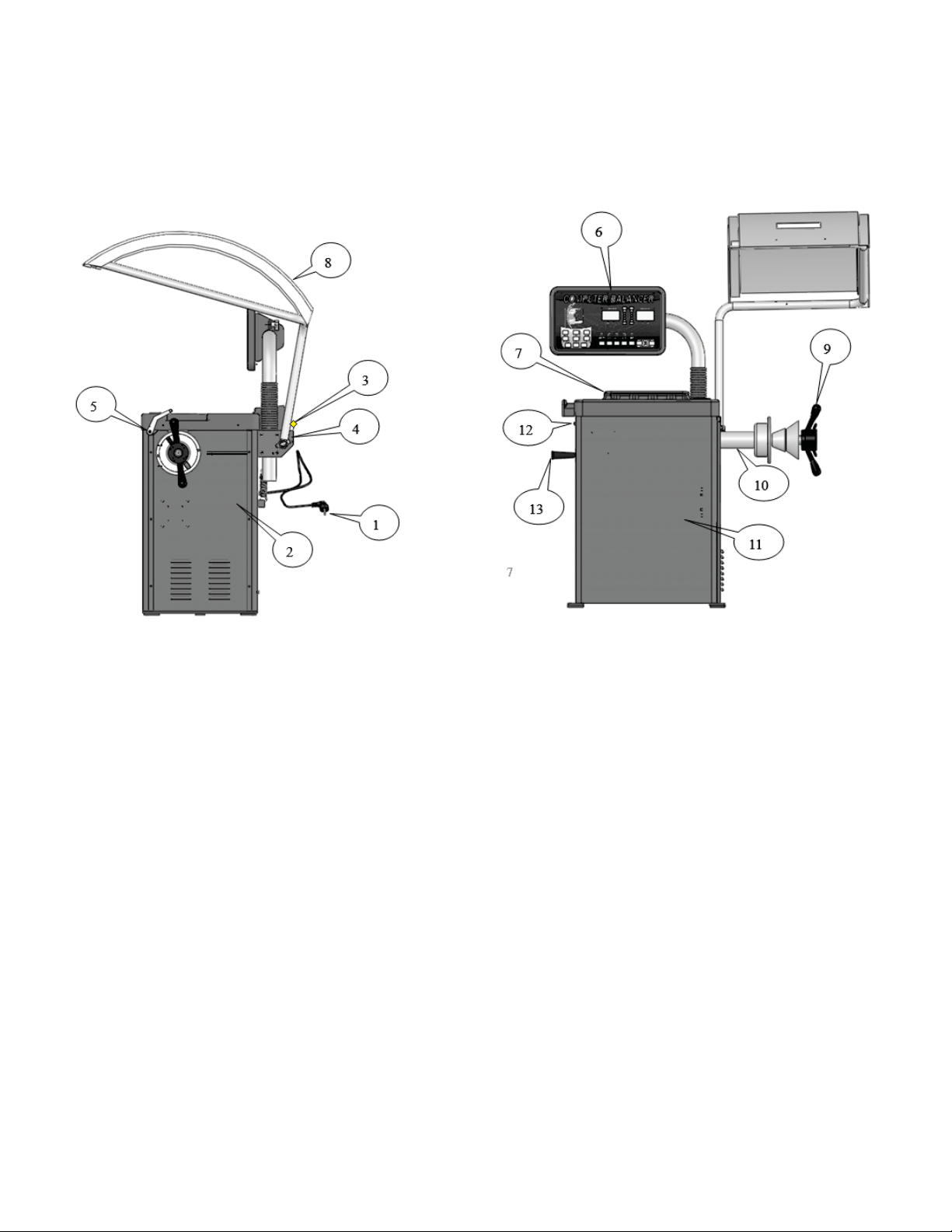
11. CONFIGURATION
1- Power Cable & Plug
2- Side Panel
3- Hood Return Spring
4- MagneƟc Hood Switch
5- Scale
6- Control Panel
7- Weight Tray
8- Hood
9- Quick Nut
10- Balance ShaŌ
11- Body
12- Power Switch
13- Cone Storage Handle
FIG. 006 FIG. 007
9
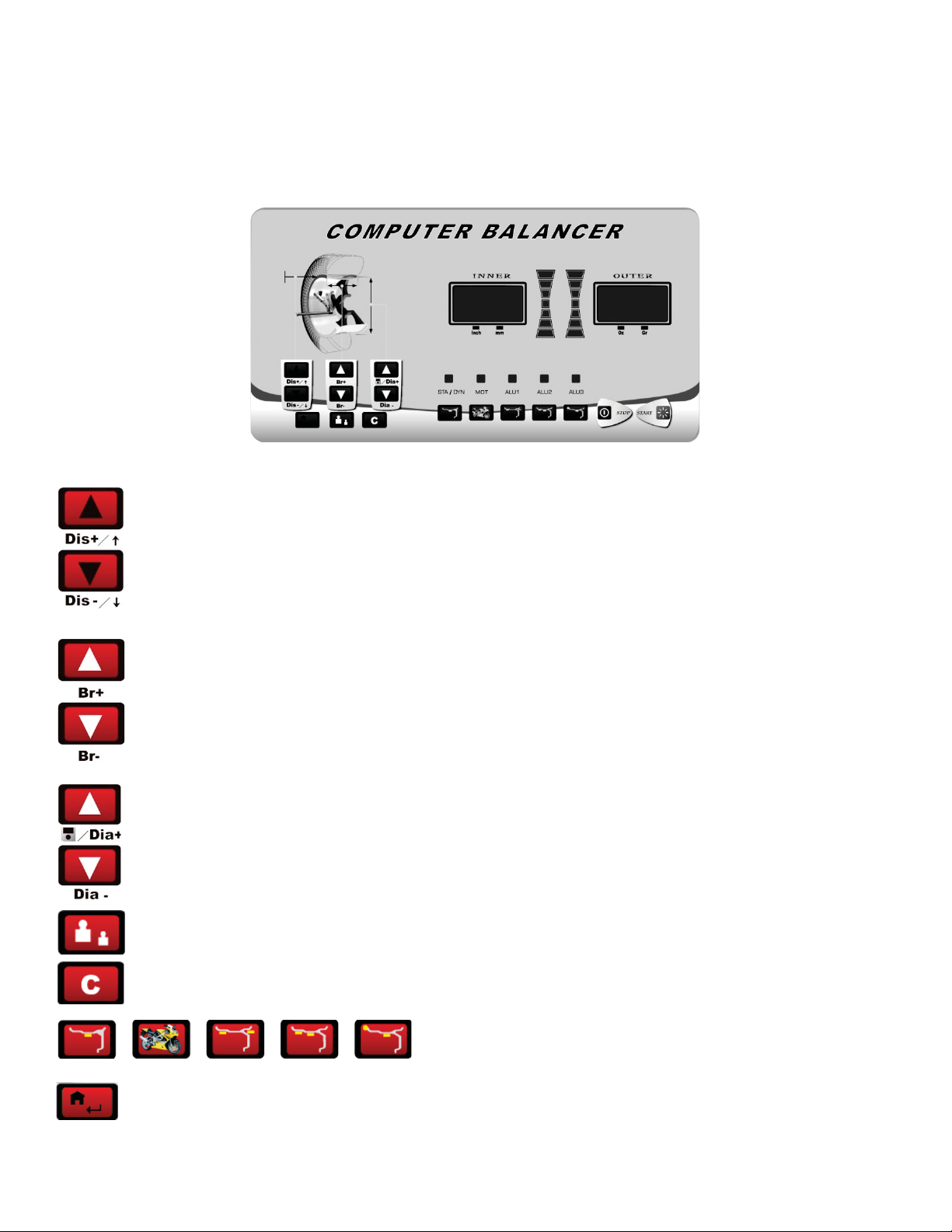
12. CONTROL PANEL
The machine control panel is shown in FIG.008. The control panel allows the operator to give commands and enter or
edit data. The same control panel displays the machine balancing results and messages.
1. This parameter input, is the distance from wheel to balancer input key .You can change
the distance set value by pressing the up/down key.
2. Br value input key. You can change the Br set value by pressing the up/down key.
3. This parameter input, it is the diameter input key. You can change the diameter set value by
pressing the up/down key.
4. High accuracy balance key: When the display displays [000], press this key and the display will display
the unbalance value less than 0.25 Oz.
5. Unit conversion key can convert the unit of measure for the unbalance, size and weight values.
6. Balancing mode selecƟon keys.
7. FuncƟon & conĮrm key (Home Key).
FIG.008
10
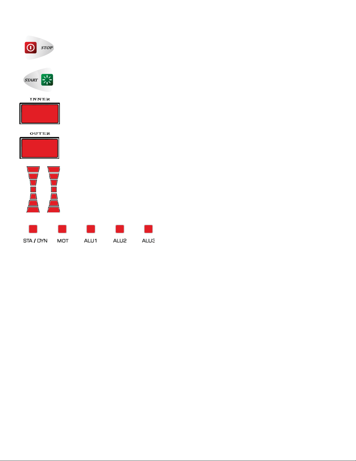
8. Emergency Stop Key.
9. Start Key.
10. Inner unbalance value and parameter display. .
11. Outside imbalance value and parameter display .
12. Unbalance posiƟon indicator.
13. Balancing modes display lamp
11

PreparaƟon beforeďĂůĂŶĐŝŶŐŚĞĐŬĨŽƌĂŶĚĐůĞĂŶĂŶLJĚŝƌƚŵƵĚĂŶĚĚĞďƌŝƐĞŵďĞĚĚĞĚŝŶƚŚĞƟƌĞĂŶĚƚƌĞĂĚƐĂŶĚĂůƐŽ
ĐŚĞĐŬƚŚĂƚƚŚĞĂŝƌƉƌĞƐƐƵƌĞŽĨƚŚĞƟƌĞŝƐƚŽƐƉĞĐŝĮĐĂƟŽŶƐŚĞĐŬĨŽƌĚĞĨŽƌŵĂƟŽŶƐŽŶƚŚĞƌŝŵƐƵƌĨĂĐĞĂŶĚŵŽƵŶƟŶŐŚŽůĞƐ
Remove the original wheel weights.
/ŶƐƚĂůůĂƟŽŶŵĞƚŚŽĚƐŽĨƚŚĞǁŚĞĞůĂƌĞƉŽƐŝƟǀĞƉŽƐŝƟŽŶŝŶŐŶĞŐĂƟǀĞƉŽƐŝƟŽŶŝŶŐĂŶĚŇĂŶŐĞĚŝƐĐƉŽƐŝƟŽŶŝŶŐzŽƵĐĂŶƐĞůĞĐƚ
ƚŚĞŵĞƚŚŽĚŽĨŵŽƵŶƟŶŐĂĐĐŽƌĚŝŶŐƚŽƚŚĞĚŝīĞƌĞŶƚĐŽŶĚŝƟŽŶƐĂŶĚƐŝnjĞƐ
13. MOUNT THE WHEEL
13.1 Wheel PosiƟve PosiƟon
PosiƟve posiƟoning is the most common method. It is simple and quick, and is mainly suitable to common steel
ƌŝŵƐĂŶĚĂůƵŵŝŶƵŵĂůůŽLJƌŝŵƐǁŝƚŚƐŵĂůůŝŵƉĞƌĨĞĐƟŽŶƐ
Main shaŌwheel cone quick nut
13.2 Wheel NegaƟve PosiƟon
WhenƚŚĞƌĞĂƌĞŝŵƉĞƌĨĞĐƟŽŶƐŽŶƚŚĞŽƵƚƐŝĚĞŽĨƚŚĞǁŚĞĞůƵƐĞƚŚŝƐŵĞƚŚŽĚŽĨƉŽƐŝƟŽŶŝŶŐƚŽŐƵĂƌĂŶƚĞĞƚŚĞ
ĂĐĐƵƌŝƚĞƉŽƐŝƟŽŶŝŶŐŽĨƚŚĞƐƚĞĞůƌŝŵƐŝŶŶĞƌŚŽůĞŽŶƚŚĞŵĂŝŶƐŚĂŌ/ƚŝƐƵƐĞĚŽŶƐƚĞĞůƌŝŵƐĂŶĚƚŚŝĐŬĞƌĂůƵŵŝŶƵŵ
rims.
Main shaŌ suitable cone wheel bowl quick nut
12

13.3 Flange Disk PosiƟoning (OpƟonal)
hƐĞĚŽŶƟƌĞĂƐƐĞŵďůŝĞƐǁŝƚŚůĂƌŐĞĐĞŶƚĞƌŚŽůĞƐŝŶƚŚĞƌŝŵ
Main shaŌ Ňange disk (Įxed on the main shaŌ) wheel cone quick nut
NOTE: The choice of the cone should be dependant on the rimĐĞŶƚĞƌŚŽůĞWĂLJĂƩĞŶƟŽŶƚŽŝƚƐĚŝƌĞĐƟŽŶŽƌŝƚ
will cause an inaccurate measurement.
14. INPUT MACHINE THREE PARAMETERS
14.1 Input DIS (Distance) Value
Pull the scale to the inner posiƟon to add the weight and press the key to input the DIS value
into the display. Once inputed, the display will show [DIS]: [XXX], the default system is mm.
14.2 Input Br (RIM Breadth) Value
Use the Br measurement caliper to measure the Br of the rim, press the key to input the Br value
into the display. Once inputed, the display will display [Br.]: [XXX], the default system is inch.
14.3 Input the DIA (Diameter) Value
AŌer conĮrming the rim diameter, press the key to input the rim diameter into the display. Once
inputed, the display will display [Dia ]: [XXX], the default system is mm.
13

༃
The unit conversion of the Br of the rim from inch to mm:
Normally, the display of Br should be in inch. When you need the unit of the display to be mm, you can use the
key to convert from inch to mm.
༄ The unit conversion of the DIA of the rim from inch to mm:
Normally, the display of DIA should be in inch. When you need the unit of the display to be mm, you can use the
key to
convert from inch to mm.
AŌer unit conversion, the unit will display values of rim Br and DIA value, but whĞŶLJŽƵƐǁŝƚĐŚƚŚĞǁŚĞĞůďĂůĂŶĐĞƌŽī
wheel balancer, the unit will be sƟll inch.
༅ The unit conversion from gram to ounce˖
Normally, the unit of the unbalance value is gram (g). If you want to measure in ounces (Oz), you can execute the
g/Oz conversion. The unit of the displayed unbalance value is gram
(g). The way to convert from gram to ounce is
to press
16
. START BUTTON
When you press the start key
the wheel balancer starts to run. A few seconds later, the machine automaƟcally stops.
The machine can also be programmed to start by lowering down the protecƟve hood.
17
. DISPLAY IMBALANCE VALUE
When the spin ends, the display will show the inner
and outer unbalance value of the rim. Use
your hand to spin the wheel.
When all of the inside and outside lightƐŽŶƚŚĞƵŶďĂůĂŶĐĞƉŽƐŝƟŽŶŝŶĚŝĐĂƚŽƌůŝŐŚƚƵƉƚŚĞ
ƉŽƐƟŽŶƚŽĂĚĚǁĞŝŐŚƚǁŝůůďĞindicated.ZŽƚĂƚĞƚŚĞǁŚĞĞůtŚĞŶƚŚĞůĞŌƐŝĚĞƉŽƐŝƟŽŶŝŶŐůĂŵƉƐĂůůůŝŐŚƚƵƉƚŚĞŚŝŐŚĞƐƚ
posiƟon is the inner unbalance posiƟon and when the right side posiƟoning lamp all light, at this moment, the highest
ƉŽƐŝƟŽŶŝƐƚŚĞŽƵƚĞƌƵŶďĂůĂŶĐĞƉŽƐŝƟŽŶĚĚƚŚĞĐŽƌƌĞƐƉŽŶĚŝŶŐǁĞŝŐŚƚĂƚƚŚĞƵŶďĂůĂŶĐĞƉŽŝŶƚĂŶĚƐƚĂƌƚƚŚĞƚĞƐƚĂŐĂŝŶ
ƵŶƟůƚŚĞďĂůĂŶĐĞŽĨƚŚĞƟƌĞŝƐĂĐŚŝĞǀĞĚ
1.
When starƟng the machine, use hand to spin the wheel to help it start rotaƟon, especially ǁŝƚŚůĂƌŐĞƌƟƌĞƐdŚŝƐ
will prolong the working life of the motor.
2.ŽŶĮƌŵƟƌĞdimensions. Check that the balance methods meet the conĮguraƟon of the rim and select the
method most easily to balance.
3.ŽŶĮƌŵƚŚĂƚƚŚĞquick lock nut is Ɵght.
4.
When the balancing process ends, remove the Ɵre. Pay aƩenƟon to handle it with care and avoid knocking the
shaŌ.
5.
When trimming the weight, use the hammer to trim the weight on the rim gently, without too much force. Do no
knock the main shaŌ too hard to avoid damaging the sensor. The posiƟon to add the weight should be free from
grease and should be dry.
14
8QEDODQFH3RVLWLRQ,QGLFDWRU
18 RESIDUAL IMBALANCE VALUE DISPLAY
The minimum value of the standard weight is 5g so if the weight you use is less than 5g, the wheel balancer will not
display the value and only displays the state of “00”. When you need to display the residual unbalance value, you should
press key and the display will immediately display the inside or outside unbalance value of less than 5g. The
maximum residual unbalance value is 4g.
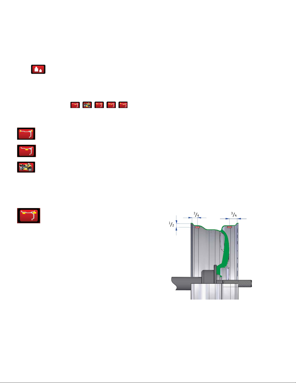
19. BALANCE MODE SELECTIONS
Press the corresponding key to choose the balance mode. If all the lights do not light up, it is
in dynamic mode.
DYNAMIC— Clip the weights on both sides of rim.
STATIC— SƟck the weight in the center.
MOT— OpƟon for balancing motorcycle rims.
When balancing motorcycle wheels, you will require the (opƟonal) motorcycle adaptor accessory MJ-II. With the
assistance of the extension scale to measure distance, Br and diameter value. Input the value into the Di, Br and Di
display window. The input method is the same as the parameter input of the car.
ALU1ˉ To balance light aluminium alloy rimƐƐƟĐŬ
the weight on the shoulders of the rim.
ALU1
15

ALU2ˉ For aluminum rim, hidden weight inside
ALU2
ALU3ˉClip the weight inside, the posiƟon to add weight outside is the same as ALU2.
ALU3
20. PROGRAM FUNCTION INTRODUCTIONS
¾Change from .1 Oz to .25 Oz (Ounce / Oz)
oPress Home Key
oPress DIS - twice
oPress Home Key
oLeŌ Right
oAPP .1 Oz
oWant .25 Oz
oPress DIS +
oLeŌ Right
oAPP .25 Oz
oPress Home Key
oPress DIA +
16

¾Change from 1g to 5g (Gram / g)
oPress Home Key
oPress DIS – twice
oPress Home Key
oLeŌ Right
oAPP 1g
oWant 5g
oPress DIS +
oLeŌ Right
oAPP 5g
oPress Home Key
oPress DIA +
21. FACTORY SETTINGS
¾Turn machine on
¾Press the following sequence of buƩons to do a Factory Reset
oPress Home Key
oPress DIS +
o“Setup” appears
oPress Home Key 2 Times
oBelow appears
oLeŌ Right
o“POS” “###”
oRotate shaŌ unƟl “111” appears in right window
oPress C
oRotate shaŌ unƟl “55” appears in right window
oPress C
oRotate shaŌ unƟl “111” appears in right window
oPress C
oBelow appears
oLeŌ Right
o“COD” “Set”
oPress Home Key
oBelow appears
oLeŌ Right
o“###” “###”
oPress DIS + unƟl “46” appears in the leŌ window
oPress Home Key
oBelow appears
oLeŌ Right
o“B-A” “###”
oPull Distance Gauge out and put to Flange – note distance on distance gauge
oThe number on the right must match the number noted on distance gauge
17

oChange the number on the right by pressing DIS + or DIS –
oPress Home Key
oBelow appears
oLeŌ Right
o“EL1” “###”
oUse DIS + or DIS – to change the number on the right to 007
oPress Home Key
oPress Home Key
oUnƟl the reset is completed with a series of beeps
oTurn the machine oī and back on
22. FACTORY CALIBRATION
Below you would Įnd the detailed instrucƟons:
Press “Home key” one Ɵme ,and it displays “[ P ]”, press “DIS + buƩon” one Ɵme , and you will see
“[ SET ]-[ UP ]”
Press “Home key” two Ɵmes , and it displays [POS—XXX], spin the wheel by hand (clock-wise or counter-clock-wise)
slowly. When it displays [POS]—[110] press the “High Accuracy Balance Key” one Ɵme ˈ
then conƟnue to spin the
it displays [POS]—[120] Press “High Accuracy Balance Key” one Ɵme.
The screen displays [ADD]-[ 0 ], press or lower down the hood to start rotaƟon of the machine.
When machine stops rotaƟon, it displays [ADD]—[100] , At thisƟŵĞ, spin the wheel unƟl the outer indicaƟng lights are
all illuminated, clamp 100g /3.5 Oz calibraƟon standard weight on the outside rim at 12 o’clock posiƟon. Press
or lower down the hood to start rotaƟon of the machine.
When the machine stops, it displays “100—ADD”. At this ƟŵĞ remove that 100g /3.5 Oz standard weight from the
outside rim edge Įrst, then spin the wheel by hand unƟl the inner indicaƟng lights are all illuminated, clamp that
100g / 3.5 Oz standard weight on the inside rim at 12 o’clock posiƟon, press
or lower down the hood to start
the rotaƟon again. When it stops, you will hear 3 Ɵmes beeps indicaƟon and the factory calibraƟon is over.
,
wheel slowly unƟl
18

23. APPENDIX
23.1 Appendix 1 - Layout of the Power Supply Card
19
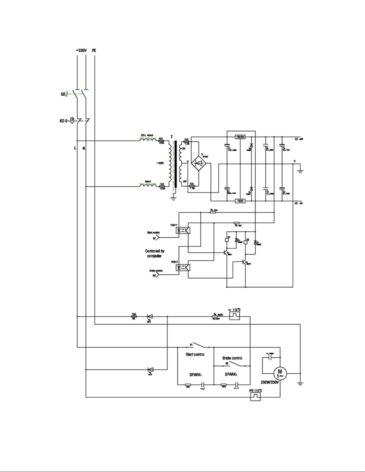
23.2 Appendix 2 - Wiring Diagram
20
Table of contents


