Ateis BOUTIQUE BTQ-VM User manual

Quick Start Guide
BOUTIQUETM
Compact and Self-Amplified
Public Address and Voice Alarm System
© 2019, ATEÏS, member of PAX ProAV Group
Revision History
v1.08

Hardware installation & connection
BTQ-VM/SG/SL mounting
Mount the BTQ-VM4/8 controller in any standard
19-inch 2U audio equipment rack using the supplied
mounting brackets and screws. Installing a BTQ-SL8/
SG8 secondary unit is similar to installing a BTQ-
VM4/VM8, except the secondary units are installed in
19-inch 1U rack-mounting.
Consider leaving enough ventilation space above and
below the unit. Do not mount the controller directly
above the heat generating devices like power supplies
or power amplifiers.
BTQ-VM/SG/SL power supply
The BTQ-VM controller has two types of power supply input, AC mains and 48VDC for battery
backup via phoenix euro-block connector, and secondary unit by 24VDC.
Connection-mains power
Connection-battery backup
To activate the power supply of BTQ-VMW wallmount controller, connect the AC mains power
first, then 48VDC battery backup input. If the order is not correct, the BTQ-VMW can not be
operated.
Ethernet (RJ45)
Connect the BTQ-VM4/8 controller and BTQ-
SG8 unit to a computer by using CAT5/6
cable.
ATEIS network (digilink and global-net)
DIGI-LINK
The BTQ-VM4/8 controller has 1 digi-link port for BTQ-SL8 secondary unit. Use STP CAT5/6 cable
with shielded RJ45 connector to connect a BTQ-SL8 secondary unit to BTQ-VM4/8 controller. Up to
31 BTQ-SL8 units can be connected under the local digi-link network.

Hardware installation & connection 3
© 2019, ATEÏS, member of PAX ProAV Group
To identify the connection among the secondary units, each secondary unit has an unique ID.
And the ID must be set orderly based on the Digi-link connection. For example, if the ID of BTQ-
VM8 controller is 1:1, then the ID of the first connected BTQ-SL8 unit on BTQ-VM8 will be 1:2,
and 1:3 for the second BTQ-SL8 unit. See Device ID to know the ID configuration.
GLOBAL-NET
Connect the BTQ-VM4/8 controller and SG8 secondary unit together through A, B port via global-net.
Device ID
The BTQ-SL8, BTQ-SG8 secondary units and DPM-MAIN paging consoles are identified by device
ID, which is configured by a DIP switch.
BTQ-SL8
BTQ-SG8
DPM-MAIN
The DIP switch of device ID is followed by the binary code
with 5 digit (BTQ-SL8), 6 digit (BTQ-SG8), 4 digit (DPM-
MAIN).
The Device ID cannot be repeated. The range of ID can be
set as the table on the right.
DIP switch
BTQ-SL8
1~31
BTQ-SG8
0~63
DPM-MAIN
0~15
Please set the ID of BTQ-SL8, BTQ-SG8 and DPM-MAIN orderly, starting by the first number.
How-to:
1. Set the device ID for BTQ-SL8/SG8 and DPM-MAIN. See
the example of BTQ-SL8 on Figure 1, the order (4~0) of
the device ID is set as 00101 by the binary code. And the
ID will be converted by the decimal code as 5, that is to
say this device will be identified with the ID number of 5.
Figure 1
2. After the ID setting and the rest of the device hardware wiring are completed, go to Web Browser
> Device Management > System Size to build a BOUTIQUE system by adding the number of

© 2019, ATEÏS, member of PAX ProAV Group
4Hardware installation & connection
controller/secondary units in the same group based on the hardware wiring.
3. Then go to Device Management to check if all the BOUTIQUE units are ''online''.
External power amplifier
The BTQ-VM4/8 controllers have an internal 250W or 500W amplifier built-in. For system power
sharing and/or backup, connect a second power amplifier (DPA or BPA) externally.
The BTQ-SL8 secondary unit can share power amplifier from BTQ-VM4/8 controller, secondary units
or connect to an external power amplifier.
Both of the controller and secondary unit are capable to handle the power up to 1000W per speaker
zone, 2000W per unit.

Hardware installation & connection 5
© 2019, ATEÏS, member of PAX ProAV Group
Battery charger (power sharing)
For DC battery backup power sharing, connect the battery charger to BTQ-VM4/8 controller and
external power amplifier as the picture below.
The example below is using the BCU-4830A/BCU-4875A battery charger and BPA or DPA power
amplifier from ATEÏS.
Digital paging console

© 2019, ATEÏS, member of PAX ProAV Group
6Hardware installation & connection
DPM-MAIN / DPM-EVA/ DPM-KPD DPM-KPD / DPM-EVA/ DPM-MAIN
The BTQ-VM4/8 controller and BTQ-SG8 secondary unit has 2 remote connections with RJ45
connectors, and the BTQ-SL8 secondary unit has 1. Each port can address up to 8 DPM-MAIN
consoles. The maximum communication cable length is 250M (820 ft.) between the controller/
secondary unit and DPM console, DPM and DPM via STP CAT5/6 cable with shielded RJ45
connector, subjects to the power supply is sufficient. Multiple DPM consoles can be wired in a
daisy-chain or redundant loop using 2 ports.
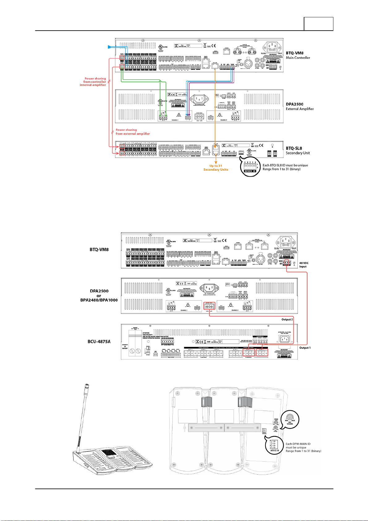
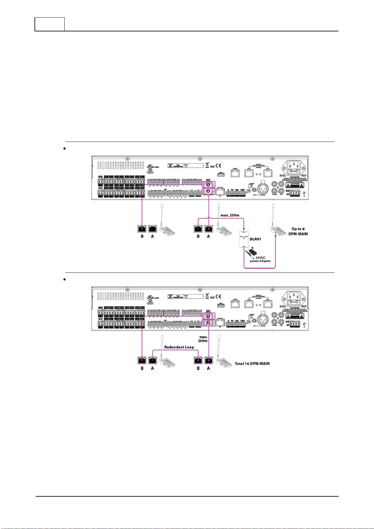
Each DPM-MAIN can attach one DPM-EVA, and up to 15 DPM-KPD can link to one DPM-MAIN by
flat cable as shown above. If the control signal of DPM units is not strong enough, the DPM needs to
connect to DLR01 digital loop repeater for expanding the distance to 250M longer. And if the power
of DPM units is not enough, connect a 24VDC local power on DLR01 Digital Loop Repeater, see the
picture below.
Daisy-chain
Redundant loop
1. Connect the [Remote Port 1] on BTQ-VM4/VM8/SG8 to the [Remote Port B] on the first set of
DPM-MAIN.
2. Connect the [Remote Port A] on the last set of DPM-MAIN to the [Remote Port 2] on BTQ-
VM4/VM8/SG8 via redundant loop.
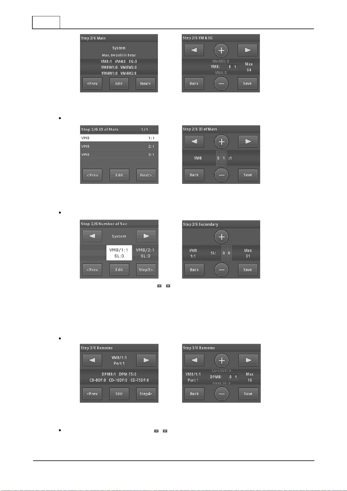
Once completed the hardware connection, run the [New Setup] Setup Wizard with 6 steps from front
LCD panel.
Setup wizard
The LCD touch panel on main controller provides system configuration, control and system status
display.

Setup wizard 7
© 2019, ATEÏS, member of PAX ProAV Group
After completed the hardware wiring, the LCD
panel will activate automatically once it is
powered.
Press the touch panel to start the system
setup.
1. New Setup (Setup Wizard)
2. Replace (replace the broken main
controller with the new one)
New setup
Step 1: language
Press [ ] on touch panel to set the
language.
Press [OK].
Step 2: number of main and secondary units & ID
Set the number of main controller and secondary unit and its ID in the system. The ID is composed
of the number of X, Y. X indicates the global net ID and Y is the local net ID.
Network
Local Network:
*for BTQ-SL8 connection
Max. digi-link units: 31
Max. cable length: 10m between units
(shielded RJ45 connector, STP CAT5/6)
Global Network:
*for BTQ-VMxx/BTQ-SG8
connection
Max. global net units: 64
Max. cable length: 100m between units
(CAT5/6), multi-mode (2km), single-mode
(20km) fibre optics
Set the number of controllers (VM4/VM8/VM8W1/VM8W2) and secondary global units (SG).

© 2019, ATEÏS, member of PAX ProAV Group
8Setup wizard
1. Press [Edit] to change the number of VM4/VM8/VM8W1/VM8W2 and SG units.
2. Press [Save] to apply settings.
Set the ID of BTQ-VM4/VM8/VM8W1/VM8W2 controller and SG unit.
1. Select the unit, and press [Edit] to change its ID.
2. Press [Save] to apply settings.
Set the number of secondary local units (SL).
1. Select [VM8/SL] block via [ ] button, and press [Edit] to change the number of SL
units.
2. Press [Save] to apply settings.
3. Press [Step3].
Step 3: number of remotes
Set the number of DPM8/DPM-T5/CD-8DF/CD-16DF/CD-T5DF on [VM8/1:1 Port 1].
1. Press [Edit] to change the number of DPM8/DPM-T5/CD-8DF/CD-16DF/CD-T5DF.
2. Press [Save] to apply settings.
Select [VM8/1:1 Port 2] block via [ ] button, and set the number of DPM8/DPM-T5/CD-8DF/
CD-16DF/CD-T5DF on [VM8/1:1 Port 2].

Setup wizard 9
© 2019, ATEÏS, member of PAX ProAV Group
Press [Save] to apply settings.
Press [Step 4].
Step 4: power amplifier(s) sharing
The power amplifier from internal amplifier of main controller and external amplifier can be shared
among the main controllers and secondary local units.
Single Amplifier
Dual Channel Amplifier
The internal amplifier in the main controller can
share power amplifier with secondary local unit
(s) to expand speaker zones.
Except the internal amplifier in the main
controller, it is possible to have second amplifier
externally for system power sharing and/or
backup.
Set the group based on the number of local-net the BOUTIQUE system has. The Group 1
indicates the amplifiers in the first local network (the internal amplifier is belonged to CH1), the
Group 2 indicates the second local network, and so on.
1. Press [Edit] to change the number of amplifier for Int. amp channel and Ext. amp channel
in the selected group.
2. Press [Save] to apply settings.
Add device and set the unit ID for power amplifier sharing.
1. Press [Edit].
2. Press [ ] to set ID for the device unit, then press [Add]/[Delete] to add or remove the
unit for power sharing in the amplifier.
3. Repeat #2 to add/delete more units.
4. Press [Save] to apply settings.

© 2019, ATEÏS, member of PAX ProAV Group
10 Setup wizard
Set CH1: Amp 1 power.
1. Press [ ] to change the power (wattage) of which Int./Ext. amplifier channel, and
[Save] the settings.
2. Press [ ] for the CH1, Amp2 settings, and repeat the same procedure for other amplifier
(s) settings.
3. Press [Step 5].
Step 5: dummy load capacitor
Calculate dummy load capacitance and DIP switch setting.
DLC Installation
1. Each speaker zone has A/B sub zones. Each sub zone requires a dummy load capacitor
in the end of speaker line.
2. Set the indicated number to ON position on the DIP switch.
3. Press [Next].
Step 6: monitoring
Set the monitor tolerance of speaker line impedance and power amplifier.
1. Press [Next] to apply the preset tolerance, impedance and amplifier gain.
Or press [Edit] to change the tolerance of percentage.
2. Press [Save] to apply settings.

Setup wizard 11
© 2019, ATEÏS, member of PAX ProAV Group
Press [Next] to get monitor reference.
Press [Ready] and [Activate] to enter the menu window.
Replace
When replacing the broken main controller with the
new one, proceed the Replace function to configure
and synchronize the system with the broken device
only.
1. If the USB flash drive is connected on BTQ-VM4/
VM8/SG8, click [Yes] to use the config. file from
USB to replace (figure 1).
If the USB flash drive is not connected, the system
will display the alert window (figure 2).
2. If not using the file from USB flash drive, click [Skip]
to skip the step.
figure 1
figure 2
Step 1: net ID
Select the netcard ID of the ''new'' BTQ-VM4/VM8 controller used to replace the broken one.
Click [Next] to apply the setting.

© 2019, ATEÏS, member of PAX ProAV Group
12 Setup wizard
Step 2: backup read
The config. files will be automatically appeared on the LCD panel once the USB flash drive is
connected to.
1. Select the config. file, and press [OK].
2. Press [Yes] to apply the config. file to the system.
3. Press [OK] to enter the menu window.
Ethermet settings
Ethernet settings: Go to Menu>Setting>Ethernet to setup IP
address/Gateway/Submask/DNS/DHCP/MAC.
Default Setting
BTQ-VM4/VM8
BTQ-SG8
IP address
192.168.102.125
192.168.102.124
Subnet Mask
255.255.252.0
255.255.252.0
Gateway
192.168.100.254
192.168.100.254
DNS
0.0.0.0
0.0.0.0
Please read the BOUTIQUE user manual to know the advanced configuration such as audio routing,
event and bell scheduler, paging with priority management, monitor, DSP parameter adjustment,
level control, fault list etc. on www.ateis.com.

Ethermet settings 13
© 2019, ATEÏS, member of PAX ProAV Group
ATEÏS Europe B.V.
EMEA
Penton Audio USA
USA, Canada & Latin America
Celsiusstraat 1 - 2652 XN Lansingerland
(Rotterdam Region), Netherlands
Tel: +31 (0) 10 2088690
info@ateis-europe.com
21 Sabin St. Pawtucket,
RI 02860, USA
Tel: 401-727-1600
Fax: 401-727-0003
info@penton-usa.com
ATEÏS France
ATEÏS China
8, rue de l'Europe -
ZA de Font Ratel,
38640 Claix, France
Tel: 33 (0) 4 76 99 26 30
contact@ateis.com
Room 610, No. 255 Wubao Road,
Minxing district, Shanghai, China
Tel: 021-54495191/92
Fax: 021-54495193
sales@ateis.com.cn
Penton UK Ltd.
UK & Ireland
Xavtel Communications RUS Ltd.
Russia
Unit 2, Teville Industrials, Dominion Way,
Worthing West Sussex,
BN14 8NW, United Kingdom
Tel: +44 (0)1903 215315
Fax: +44 (0)1903 215415
sales@pentonuk.co.uk
Russian Federation, 115280, Moscow
Leninskaya Sloboda str., 26 bld. 28, Business
Center "Slobodskoy", office #122
Tel: +7 495 803 3655
Fax: +7 495 803 3655
info@xavtel.ru.com
ATEÏS Far East CORP.
Far-East Asia
ATEÏS Suisse SA
Switzerland & South-East Europe
No.60, Xinghua 2nd Rd, Tanzi,
Taichung 427, Taiwan
Tel: +886-4-25333820
Fax: +886-4-25333830
sales@ateis-fareast.com
Avenue des Baumettes 9,
1020 Renens VD, Switzerland
Tel: +41 (0) 21 881 25 10
Fax: +41 (0) 21 881 25 09
info@ateis.ch
ATEÏS Middle East
ATEÏS SE PTE Ltd.
South-East Asia
Light Industrial Unit 11 Dubai
Silicon Oasis, Dubai United Arab Emirates
Tel: +971 4 3262730
Fax: +971 4 3262731
info@ateis.ae
Blk 5002 Ang Mo Kio Avenue 5, #03-01B
TECHplace II. Singapore 569871
Tel: +65 6481 1968
Fax: +65 6481 1960
info@ateis-se.com.sg
This manual suits for next models
2
Table of contents
Other Ateis Security System manuals
Popular Security System manuals by other brands

Bosch
Bosch DS938Z installation guide

Johnson Controls
Johnson Controls IFC-1010 Hardware installation

Nokia
Nokia IP200 Series installation guide

Teletek electronics
Teletek electronics BRAVO Installation and operation manual

Uniden
Uniden Guardian G455 user guide

Gemini
Gemini 933 Series Installation and use manual