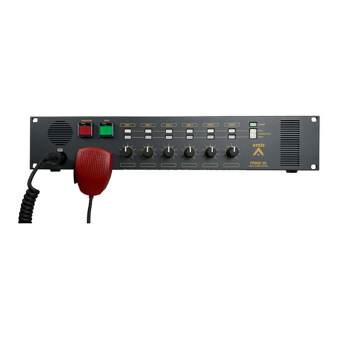
Ateis BOUTIQUE BTQ-VM425W1 User manual

© 2019, ATEÏS, member of PAX ProAV Group
Revision History
v1.13
BOUTIQUETM
Compact and Self-Amplified
Public Address and Voice Alarm System
User ManualUser Manual

2
© 2019, ATEÏS, member of PAX ProAV Group
Table of Contents Page
1 About this manual 8
................................................................................................................................... 81.11.1 Firmware version
................................................................................................................................... 81.21.2 Notice signs
................................................................................................................................... 81.31.3 Safety instructions
................................................................................................................................... 91.41.4 Related documentation
2 System overview 10
................................................................................................................................... 102.12.1 BOUTIQUE PA/VA system
................................................................................................................................... 102.22.2 BTQ-VM4/VM8 - PAVA controller
.......................................................................................................................................................... 11
Front panel
2.2.1
.......................................................................................................................................................... 13
Rear panel
2.2.2
................................................................................................................................... 152.32.3 BTQ-VM4W/VM8W - wallmount PAVA controller
.......................................................................................................................................................... 16
Front panel
2.3.1
.......................................................................................................................................................... 17
Rear panel
2.3.2
................................................................................................................................... 172.42.4 BTQ-SG8/BTQ-SL8 - PAVA secondary global/local unit
.......................................................................................................................................................... 18
Front panel
2.4.1
.......................................................................................................................................................... 19
Rear panel
2.4.2
................................................................................................................................... 212.52.5 Digital paging console
.......................................................................................................................................................... 21
DPMpaging microphone/microphone keypad/speaker pad
2.5.1
......................................................................................................................................................... 22
DPM-MAIN - digital redundant loop paging microphone-main
2.5.1.1
......................................................................................................................................................... 24
DPM-KPD - additional 8+1 microphone keypad
2.5.1.2
......................................................................................................................................................... 25
DPM-EVA - EVAC unit with speaker and extra buttons
2.5.1.3
.......................................................................................................................................................... 27
DPM-T5/DPM-T5F touchpanel paging mic
2.5.2
......................................................................................................................................................... 28
Front panel
2.5.2.1
......................................................................................................................................................... 29
Side & rear panel
2.5.2.2
.......................................................................................................................................................... 29
CD-8DF/CD-16DF wallmount paging mic
2.5.3
......................................................................................................................................................... 30
Front panel
2.5.3.1
.......................................................................................................................................................... 31
CD-T5DF wallmount touchpanel paging mic
2.5.4
......................................................................................................................................................... 32
Front panel
2.5.4.1
................................................................................................................................... 332.62.6 Accessories
.......................................................................................................................................................... 33
DNM2-ETH digital ambient noise sensing mic, Ethernet
2.6.1
.......................................................................................................................................................... 33
DGL-MIC flush/ceiling mount microphone
2.6.2
......................................................................................................................................................... 33
DGL-MIC front panel/rear panel
2.6.2.1
.......................................................................................................................................................... 34
DLR01 - digital loop repeater
2.6.3
......................................................................................................................................................... 34
Top panel
2.6.3.1
......................................................................................................................................................... 34
Side panel
2.6.3.2
......................................................................................................................................................... 35
Front & rear panel
2.6.3.3
.......................................................................................................................................................... 35
RAC 5/RAC 8 remote controller
2.6.4
.......................................................................................................................................................... 35
VAT volume attenuator
2.6.5
.......................................................................................................................................................... 36
VA-DLC dummy load capacitor module
2.6.6
.......................................................................................................................................................... 36
VA-EOL end of SP-line module for multi-branch/3-wire
2.6.7
.......................................................................................................................................................... 36
SL-SENSOR2/SL-SENSOR4
2.6.8
................................................................................................................................... 372.72.7 Network cards
3 Hardware installation & connection 38
................................................................................................................................... 383.13.1 BTQ-VM/SG/SL power supply
................................................................................................................................... 383.23.2 BTQ-VM/SG/SL mounting
................................................................................................................................... 383.33.3 BTQ-VM4W/VM8W mounting
.......................................................................................................................................................... 38
Locating the BTQ-VM4W/VM8W
3.3.1
.......................................................................................................................................................... 39
BTQ-VM4W/VM8W wiring
3.3.2
.......................................................................................................................................................... 42
Mounting the batteries in BTQ-VM4W/VM8W
3.3.3

3Contents
© 2019, ATEÏS, member of PAX ProAV Group
................................................................................................................................... 443.43.4 ATEIS network (digilink and global-net)
.......................................................................................................................................................... 44
DIGI-LINK
3.4.1
.......................................................................................................................................................... 45
GLOBAL NET
3.4.2
................................................................................................................................... 453.53.5 Ethernet (RJ45)
................................................................................................................................... 453.63.6 Digital paging console
.......................................................................................................................................................... 46
Redundant loop/daisy-chain wiring
3.6.1
.......................................................................................................................................................... 46
DPM-T5/DPM-T5F/CD-8DF/CD-16DF/CD-T5DF
3.6.2
................................................................................................................................... 463.73.7 DLR01
................................................................................................................................... 473.83.8 External power amplifier
................................................................................................................................... 483.93.9 Battery charger (power sharing)
................................................................................................................................... 493.103.10 Loudspeakers
................................................................................................................................... 493.113.11 VA-DLC dummy load capacitor module
................................................................................................................................... 493.123.12 Multi-branch/3-wire
.......................................................................................................................................................... 50
VA-EOL branch wiring with VAT
3.12.1
.......................................................................................................................................................... 51
Device ID setting
3.12.2
................................................................................................................................... 513.133.13 Logic inputs
................................................................................................................................... 523.143.14 EVAC inputs
................................................................................................................................... 523.153.15 Mic/Line input with VOX (XLR)
................................................................................................................................... 523.163.16 BGM inputs (RCA)
................................................................................................................................... 533.173.17 RAC 5/RAC 8
................................................................................................................................... 533.183.18 DNM2-ETH
.......................................................................................................................................................... 53
Installation notice
3.18.1
4 Hardware configuration & operation 55
................................................................................................................................... 554.14.1 BTQ-VM LCD panel
.......................................................................................................................................................... 55
Setup wizard
4.1.1
......................................................................................................................................................... 55
New setup
4.1.1.1
......................................................................................................................................... 55
Step 1: language
4.1.1.1
......................................................................................................................................... 55
Step 2: number of main and secondary units & ID
4.1.1.1
......................................................................................................................................... 57
Step 3: number of remotes
4.1.1.1
......................................................................................................................................... 57
Step 4: power amplifier(s) sharing
4.1.1.1
......................................................................................................................................... 58
Step 5: dummy load capacitor
4.1.1.1
......................................................................................................................................... 59
Step 6: monitoring
4.1.1.1
......................................................................................................................................................... 60
Replace
4.1.1.2
......................................................................................................................................... 60
Step 1: net ID
4.1.1.2
......................................................................................................................................... 60
Step 2: backup read
4.1.1.2
.......................................................................................................................................................... 61
LCD menu
4.1.2
......................................................................................................................................................... 61
Mic Line/FMM/Recovery/Log List/Fault List/Logout Login
4.1.2.1
......................................................................................................................................................... 63
Monitor/System Reset/Paging Reset/LAMP Test/Setup
Replace
4.1.2.2
......................................................................................................................................................... 64
Setting
4.1.2.3
......................................................................................................................................................... 67
Privilege setting
4.1.2.4
................................................................................................................................... 674.24.2 DPM-T5/DPM-T5F/CD-T5DF LCD panel
.......................................................................................................................................................... 69
Button status
4.2.1
.......................................................................................................................................................... 69
Chime/talk
4.2.2
.......................................................................................................................................................... 70
Modify zone
4.2.3
.......................................................................................................................................................... 70
Monitor
4.2.4
.......................................................................................................................................................... 70
Message
4.2.5
.......................................................................................................................................................... 71
Routing
4.2.6
.......................................................................................................................................................... 72
Fault
4.2.7
.......................................................................................................................................................... 73
Setting
4.2.8
.......................................................................................................................................................... 74
Stack paging
4.2.9

4
© 2019, ATEÏS, member of PAX ProAV Group
................................................................................................................................... 754.34.3 DPM/DPM-T5 key configuration
................................................................................................................................... 764.44.4 Device ID
................................................................................................................................... 774.54.5 Route BGM sources to zones
................................................................................................................................... 784.64.6 Messages and microphone calls
.......................................................................................................................................................... 79
EVAC
4.6.1
.......................................................................................................................................................... 79
Alert
4.6.2
.......................................................................................................................................................... 79
MSG test
4.6.3
.......................................................................................................................................................... 80
Fireman microphone
4.6.4
5 Configuration 81
................................................................................................................................... 815.15.1 Web browser
.......................................................................................................................................................... 81
Setup wizard
5.1.1
......................................................................................................................................................... 81
New setup
5.1.1.1
......................................................................................................................................... 81
Step 1: language
5.1.1.1
......................................................................................................................................... 81
Step 2: number of main and secondary unit
5.1.1.1
......................................................................................................................................... 82
Step 3: number of remotes
5.1.1.1
......................................................................................................................................... 82
Step 4: power amplifier(s) sharing
5.1.1.1
......................................................................................................................................... 83
Step 5: dummy load capacitor
5.1.1.1
......................................................................................................................................... 83
Step 6: Monitoring
5.1.1.1
......................................................................................................................................................... 84
Replace
5.1.1.2
......................................................................................................................................... 84
Step 1: net ID
5.1.1.2
......................................................................................................................................... 84
Step 2: backpup read/recovery
5.1.1.2
.......................................................................................................................................................... 85
Getting started
5.1.2
.......................................................................................................................................................... 85
User management
5.1.3
......................................................................................................................................................... 86
User level
5.1.3.1
......................................................................................................................................... 86
LCD panel & web browser
5.1.3.1
......................................................................................................................................................... 87
Add user
5.1.3.2
......................................................................................................................................................... 88
Modify user
5.1.3.3
......................................................................................................................................................... 88
Delete user
5.1.3.4
......................................................................................................................................................... 88
Login/logout
5.1.3.5
.......................................................................................................................................................... 88
Synchronize icon
5.1.4
.......................................................................................................................................................... 88
Configuration file upload/download
5.1.5
.......................................................................................................................................................... 89
System
5.1.6
......................................................................................................................................................... 89
Device management
5.1.6.1
......................................................................................................................................... 89
System size
5.1.6.1
......................................................................................................................................... 89
Hide units
5.1.6.1
......................................................................................................................................... 89
Add/delete remotes
5.1.6.1
................................................................................................................................... 90
Add a DPM-MAIN/DPM-T5/CD-8DF/CD-16DF/CD-T5DF
5.1.6.1.3
................................................................................................................................... 91
Add a DNM2-ETH
5.1.6.1.3
................................................................................................................................... 91
Add a DGL-MIC
5.1.6.1.3
......................................................................................................................................... 92
Setting
5.1.6.1
................................................................................................................................... 93
Application1: economic type
5.1.6.1.4
................................................................................................................................... 93
Application2: medium scale type
5.1.6.1.4
................................................................................................................................... 94
Application3: large scale type
5.1.6.1.4
......................................................................................................................................... 95
Modulation
5.1.6.1
................................................................................................................................... 95
DNM2-ETH/DGL-MIC
5.1.6.1.5
................................................................................................................................... 96
DPM-T5/CD-T5DF screen calibration
5.1.6.1.5
......................................................................................................................................................... 96
Site device list
5.1.6.2
......................................................................................................................................................... 97
Power consumption
5.1.6.3
......................................................................................................................................................... 98
Update
5.1.6.4
......................................................................................................................................... 98
Firmware
5.1.6.4
......................................................................................................................................... 98
Language
5.1.6.4
......................................................................................................................................... 99
Skin
5.1.6.4
......................................................................................................................................................... 99
Table synchronization
5.1.6.5
.......................................................................................................................................................... 100
Machine
5.1.7
......................................................................................................................................................... 100
Settings
5.1.7.1
......................................................................................................................................... 100
General
5.1.7.1

5Contents
© 2019, ATEÏS, member of PAX ProAV Group
......................................................................................................................................... 100
FP saver
5.1.7.1
......................................................................................................................................... 100
IP
5.1.7.1
......................................................................................................................................... 101
SIP
5.1.7.1
......................................................................................................................................... 102
Date/time
5.1.7.1
......................................................................................................................................... 102
Syslog (central log service)
5.1.7.1
......................................................................................................................................... 103
RS232 port
5.1.7.1
......................................................................................................................................... 103
Third party controls
5.1.7.1
......................................................................................................................................... 103
Zone settings
5.1.7.1
......................................................................................................................................... 104
Security mode (power saving)
5.1.7.1
......................................................................................................................................... 104
Power monitor
5.1.7.1
......................................................................................................................................... 105
FP speaker
5.1.7.1
......................................................................................................................................... 105
Backup amp setting
5.1.7.1
......................................................................................................................................... 105
Stream out
5.1.7.1
......................................................................................................................................................... 106
Message
5.1.7.2
......................................................................................................................................... 106
Management
5.1.7.2
......................................................................................................................................... 107
Playlists
5.1.7.2
......................................................................................................................................................... 107
Info
5.1.7.3
......................................................................................................................................... 107
Fault list
5.1.7.3
......................................................................................................................................... 108
Log list
5.1.7.3
......................................................................................................................................... 108
About
5.1.7.3
......................................................................................................................................................... 108
Status
5.1.7.4
.......................................................................................................................................................... 109
Function
5.1.8
......................................................................................................................................................... 109
Scheduler
5.1.8.1
......................................................................................................................................... 110
Add/edit/delete
5.1.8.1
......................................................................................................................................... 111
Edit repeated event
5.1.8.1
......................................................................................................................................................... 111
Logic I/O
5.1.8.2
......................................................................................................................................... 112
Evacuation inputs
5.1.8.2
................................................................................................................................... 113
Edit evac/alarm event
5.1.8.2.1
......................................................................................................................................... 115
Normal logic inputs
5.1.8.2
......................................................................................................................................... 116
RAC calibration
5.1.8.2
......................................................................................................................................... 117
Relay outputs
5.1.8.2
......................................................................................................................................................... 117
Paging
5.1.8.3
......................................................................................................................................... 118
Add singular type
5.1.8.3
................................................................................................................................... 119
MSG TEST/ALERT/EVAC
5.1.8.3.1
................................................................................................................................... 119
FIREMAN
5.1.8.3.1
................................................................................................................................... 120
MIC
5.1.8.3.1
................................................................................................................................... 121
CD/AUX
5.1.8.3.1
................................................................................................................................... 121
MEMORY
5.1.8.3.1
................................................................................................................................... 121
INTERNET
5.1.8.3.1
................................................................................................................................... 122
VOIP
5.1.8.3.1
......................................................................................................................................... 122
Add integration type
5.1.8.3
................................................................................................................................... 124
DPM-T5 Record/Listen/Paging
5.1.8.3.2
................................................................................................................................... 125
DTMF intercom call
5.1.8.3.2
................................................................................................................................... 127
DTMF paging call via Modbus
5.1.8.3.2
......................................................................................................................................... 128
Security/evacuation option
5.1.8.3
.......................................................................................................................................................... 129
Third party
5.1.9
.......................................................................................................................................................... 130
Event
5.1.10
......................................................................................................................................................... 130
Event set
5.1.10.1
......................................................................................................................................... 130
Security mode
5.1.10.1
......................................................................................................................................... 131
Scheduler switch
5.1.10.1
......................................................................................................................................... 131
Wave select
5.1.10.1
......................................................................................................................................... 131
Stop paging
5.1.10.1
......................................................................................................................................... 132
Fault active
5.1.10.1
......................................................................................................................................... 132
Fault inactive
5.1.10.1
......................................................................................................................................... 132
Evac input reset
5.1.10.1
......................................................................................................................................... 133
USB backup
5.1.10.1
......................................................................................................................................................... 133
Add event & zone selection settings
5.1.10.2
......................................................................................................................................................... 134
Logic out
5.1.10.3
......................................................................................................................................................... 135
Command string
5.1.10.4

6
© 2019, ATEÏS, member of PAX ProAV Group
......................................................................................................................................................... 135
Marco
5.1.10.5
......................................................................................................................................................... 136
DSP element
5.1.10.6
......................................................................................................................................................... 136
Message routing
5.1.10.7
......................................................................................................................................................... 137
Singular paging
5.1.10.8
......................................................................................................................................................... 137
Singular paging on by zone
5.1.10.9
......................................................................................................................................................... 137
Singular paging off by zone
5.1.10.10
.......................................................................................................................................................... 137
Monitor
5.1.11
......................................................................................................................................................... 137
Global settings
5.1.11.1
......................................................................................................................................................... 138
Zones
5.1.11.2
......................................................................................................................................... 138
Control
5.1.11.2
......................................................................................................................................... 140
Monitoring settings of zone (A/B zone)
5.1.11.2
......................................................................................................................................... 141
Monitoring settings of VA-EOL (3 wire)
5.1.11.2
......................................................................................................................................... 142
Faults
5.1.11.2
......................................................................................................................................................... 142
Amplifiers
5.1.11.3
......................................................................................................................................... 142
Control & display
5.1.11.3
......................................................................................................................................... 143
Faults
5.1.11.3
......................................................................................................................................................... 143
Leakage
5.1.11.4
......................................................................................................................................... 144
Faults
5.1.11.4
.......................................................................................................................................................... 145
DSP function
5.1.12
......................................................................................................................................................... 145
DSP Structure
5.1.12.1
......................................................................................................................................... 145
Source settings
5.1.12.1
................................................................................................................................... 146
Message
5.1.12.1.1
......................................................................................................................................... 146
Compoments
5.1.12.1
................................................................................................................................... 146
Equalizer
5.1.12.1.2
................................................................................................................................... 147
Dynamic
5.1.12.1.2
................................................................................................................................... 149
Internal/external CH output
5.1.12.1.2
................................................................................................................................... 149
Ambient noise sensing microphone (static & dynamic)
5.1.12.1.2
................................................................................................................................... 150
Static
5.1.12.1.2
................................................................................................................................... 151
Dynamic
5.1.12.1.2
................................................................................................................................... 152
Calibration
5.1.12.1.2
......................................................................................................................................... 152
Stream out
5.1.12.1
......................................................................................................................................................... 153
Parameter range
5.1.12.2
6 Maintenance 154
7 Fault lists & troubleshooting 155
8 Technical data 162
................................................................................................................................... 1628.18.1 BTQ-VM4/VM8
................................................................................................................................... 1648.28.2 BTQ-VM4W/VM8W
................................................................................................................................... 1678.38.3 BTQ-SG8/BTQ-SL8
................................................................................................................................... 1688.48.4 Digital paging consoles
.......................................................................................................................................................... 168
DPM-MAIN
8.4.1
.......................................................................................................................................................... 170
DPM-EVA/DPM-KPD
8.4.2
.......................................................................................................................................................... 171
DPM-T5/DPM-T5F
8.4.3
.......................................................................................................................................................... 172
CD-8DF/CD-16DF
8.4.4
.......................................................................................................................................................... 173
CD-T5DF
8.4.5
................................................................................................................................... 1748.58.5 Accessories
.......................................................................................................................................................... 174
DNM2-ETH
8.5.1
.......................................................................................................................................................... 175
DGL-MIC
8.5.2
.......................................................................................................................................................... 175
DLR01
8.5.3
.......................................................................................................................................................... 175
VAT-35U
8.5.4
.......................................................................................................................................................... 176
VA-DLC
8.5.5
.......................................................................................................................................................... 176
VA-EOL
8.5.6
.......................................................................................................................................................... 177
SL-SENSOR2/SL-SENSOR4
8.5.7
.......................................................................................................................................................... 177
Network cards
8.5.8
9 Contact information 179

7Contents
© 2019, ATEÏS, member of PAX ProAV Group

8
© 2019, ATEÏS, member of PAX ProAV Group
1 About this manual
This user manual will explicitly describe the hardware installation and the software configuration,
provides installers and users the necessary information to setup and configure the system.
1.1 Firmware version
Version
v2.41
1.2 Notice signs
** The above warning is located on the back of the unit.
Explanation of Graphical Symbols
The equipment or the property can be damaged,
or persons can be lightly injured if the alert is
not observed.
To alert the user to the presence of uninsulated
“dangerous voltage” within the product’s enclosure
that may be of sufficient magnitude to constitute a
risk of electric shock to persons.
1.3 Safety instructions
Do not expose the device to extreme temperatures, direct sunlight, humidity, or dust, which could
cause fire or electrical shock hazard.
Keep away water or other liquids from the device. Otherwise fire or electrical shock may result.
Connect the power cord only to an AC outlet of the type stated in this manual or as marked on the
unit. Otherwise fire and electrical shock hazard results.
When disconnecting the power cord from an AC outlet always grab the plug. Never pull the cord. A
damaged power cord is a potential risk of fire and electrical shock hazard.
Avoid touching power plugs with wet hands. Doing so is a potential electrical shock hazard.
Take care for correct polarity when operating the device from a DC power source. Reversed polarity
may cause damage to the unit or the batteries.
Avoid placing heavy objects on power cords. A damaged power cord is a fire and electrical shock
hazard.
Do not cut, scratch, bend, twist, pull, or heat the power cord. A damaged power cord is a fire and
electrical shock hazard. Ask your ATEÏS dealer for replacement.
Turn off the unit immediately, remove the power cord from the AC outlet and contact your ATEÏS
dealer in any of the following circumstances, if you continue using the device, fire and electrical

About this manual 9
© 2019, ATEÏS, member of PAX ProAV Group
shock may result.
oSmoke, odor, or noise getting out of the unit.
oForeign objects or liquids get inside the device.
oThe unit has been dropped or the shell is damaged.
Do not drop or insert metallic objects or flammable materials into the unit as this may result in fire
and electrical shock.
Do not remove the device's cover, as there are exposed parts inside carrying high voltages that
may cause an electrical shock. Contact your ATEÏS dealer if internal inspection, maintenance or
repair is necessary.
Do not try to make any modifications to the device. This is a potential fire and electrical shock
hazard.
Avoid the device's ventilation slots to be blocked. Blocking the ventilation slots is a potential fire
hazard.
To prevent the unit from falling down and causing personal injury and/or property damage, avoid
installing or mounting the unit in unstable locations.
Leave enough space above and below the unit to provide good ventilation of the device. If the airflow
is not adequate, the device will heat up inside and may cause a fire.
Operate the device in an environment with a free-air temperature of between -5°C ~ +55°C (+23°F
~ +131°F).
Turn off all audio equipment when making any connections to the device, and make sure to use
adequate cables.
Do not use benzene, thinner or chemicals to clean the device. Use only a soft, dry cloth.
If the device is moved from a cold place (e.g., overnight in a car) to a warmer environment,
condensation may form inside the unit, which may affect performance. Allow the device to
acclimatize for about one hour before use.
1.4 Related documentation
The following related documents are available:
BOUTIQUE Quick Start Guide.
Refer to the product related information on www.ateis.com

10
© 2019, ATEÏS, member of PAX ProAV Group
2 System overview
2.1 BOUTIQUE PA/VA system
The BOUTIQUE is an integrated, self-amplified PA/VA system. It has all the essential functionalities
to comply with EN-54 and UL2572 requirements including speaker lines monitoring, EVAC
microphone capsule and cable surveillance, micro controller watchdog and memory testing etc..
2.2 BTQ-VM4/VM8 - PAVA controller
The BTQ-VM4/8 is an compact public address and voice alarm controller with 250W or 500W high
efficiency Class-D amplifier built-in. Varies functions such as system ''easy setup'' function, providing
installer an ease of installation and configuration directly from LCD front panel. The BOUTIQUE
system expands from a single controller capable of as little as 4 zones, to a larger networked
system of up to 16,384 zones, making the system suitable for a wide variety of applications. The
controller features EVAC paging, event and bell scheduler, audio routing, paging with priority
management, network redundancy, low cost amplifier switching, amplifier monitor, backup etc. can
be configured via web browser.
BTQ-VM425 / BTQ-VM450
BTQ-VM825 / BTQ-VM850

System overview 11
© 2019, ATEÏS, member of PAX ProAV Group
Components included:
Fireman microphone and evacuation button
Amplifier built-in
250W or 500W high efficiency Class-D amp built-in and is capable of handling 1000W
speaker load per zone and 2000W max. per unit.
Internal digital message storage with 90 minutes of memory storage and USB interface
available.
Supervision
oAdvanced configuration, diagnostics and logging via web browser.
oEnhanced loudspeaker line surveillance (short, open, bad impedance) for speaker zone
wiring (A/B).
oFull monitoring of paging microphones and auto backup for external power amplifiers when
one of them breaks down.
oVolume attenuators can be installed on monitored speaker lines without loopback cabling.
This feature is supported only for the model with EOL Driver such as BTQ-VMD825, BTQ-
VMD450, in the model number, "D" means EOL Driver.
2.2.1 Front panel
1. Fireman microphone & U-shape bracket:
A fully monitored microphone is designed for EVAC paging. The paging button supports both
press-to-talk and lock-to-talk mode. The talk mode can be set via web browser.
2. Monitoring speaker:
This built-in speaker is to monitor the zone audio including message and BGM. When the faults
detected by the system, the system will generate a buzzer sound (tone) as warning.
3. Evacuation button:
Once this button is pushed, the system will enter to emergency state. Its LED will light up and
play the EVAC messages.
4. Power LED:
This LED lights up when the controller is powered.
5. Fault LED:
This LED lights up when one or more faults are detected.

12
© 2019, ATEÏS, member of PAX ProAV Group
6. Reset button:
This button is used to reset the emergency state. The evac message playing will be canceled,
and the red evacuation button will light off.
7. Active LED (fireman microphone):
The LED will light up when the fireman microphone is under paging.
8. Touch screen panel:
2.2" color touch panel offers a graphical interface to control, configure and display the status
of system.
9. + - button:
Navigate as volume up/down or increase/decrease control.
10. button:
Navigate as up/down control.
11. ESC button:
Navigate as go back to previous page.
12. OK button:
Navigate as next/save action. See more details about the LCD Front Panel.
13. MSG Test button and LED:
A button to manually play the testing alert message to the selected or pre-defined zones, and a
LED will light up as long as the button is pushed.
14. Alert button and LED:
A button to manually play the alert message to selected or pre-defined zones, and a LED will
light up as long as the button is pushed.
15. All Call/Cancel button:
A button to select all the zones in the entire BOUTIQUE system or reset the current zone
selection.
16. Route button:
A button to manually route the selected music source (CD/Tuner/Aux/USB/Internet) to selected
or pre-defined zones.
17. Select button:
A button to manually select the music source (CD/Tuner/Aux/USB/Internet) to be routed.
18. CD/Tuner/Aux/USB/Internet LED:
Four LEDs to indicate which music source is active.
19. Selected zone button:
Select or deselect the zone for manual music routing or message/EVAC paging (CD/Tuner/Aux/
USB/Internet/fireman mic/XLR mic).
If none of the zones among controllers and secondary units are selected on the front panel, the
system will route to the zones configured by web browser.
20~22. VACIE indicator LED:
There are 4 or 8 rows of 3 LEDs that show real-time mode of the status of zone:
20. Selected LED (4 or 8 zones): The blue LED will light up to indicate the selection of
zones.

System overview 13
© 2019, ATEÏS, member of PAX ProAV Group
21. EVAC LED: The red LED will light up if the zone is in evacuation paging.
22. Alert/Page LED: The blue LED will light up if the zone is under paging (except for
evacuation paging).
23. Volume control knob (4 or 8 zones):
Individual zone rotary knobs to set the volume of BGM.
This knob is for audio source using internal amplifier, normally it's background music.
24. Air inlet holes:
The BTQ-VM4/8 controller has a cooling fan that takes in air from the front panel and exhausts it
from the rear panel. Please make sure that these inlet holes are not obstructed.
2.2.2 Rear panel
1. Internal amp output:
The output provides the 100V (EU type)/70V (US type) audio signal of internal power amplifier to
the BTQ-SL units.
2. External amp output:
This terminal connects to output of external amplifier.
3. A/B line zone outputs:
The BTQ-VM4 has 4 zones and BTQ-VM8 has 8 zones. Connect the loudspeakers to the zone
outputs. Each zone output is consisted of two loudspeaker line outputs. The open, short and
bad impedance faults can be detected by system for both speaker lines.
The controller is capable of handling 1000W speaker load per zone, 2000W max. per unit.
4. Relay control output:
There are eight relay outputs on BTQ-VM8 controller and four on BTQ-VM4 controller, they can
be programmed as close/open contact to an external device.
5. EVAC input:
There are nine EVAC inputs on BTQ-VM8 and five EVAC inputs on BTQ-VM4. The evac inputs
are N.O. (normally open) contact. They can be programmed for phase evacuation and to monitor
the external contact.
Each channel supports 3 modes:
Monitored contact mode: The system can monitor the evac input and detect faults (4
status: on, off, open and short).
Disable: The cables which connect to evacuation input will not be monitored (faults will not
be detected).

14
© 2019, ATEÏS, member of PAX ProAV Group
Voltage mode: Trigger the input by a voltage change (OPEN/CLOSE) with an external
24VDC source provided by external devices. The cable is not monitored in this mode.
6. 24 VDC output:
Provide 24VDC (max. 1.3A) power for external devices. Please note the power is shared by the
two 24VDC outputs on BTQ-VM4/8 controller and the remote consoles.
7. Logic input:
There are eight logic inputs designed to work with simple contact or button, and the two states
input (open contact, close contact) can be specified to any of those logic input to monitor
security devices such as power supply, then those control inputs can put the system into a
security mode for power saving purpose.
8/9. Evac & Fault contacts output:
The Evac and Fault output contact will reflect the evacuation status and the general fault status
of the BOUTIQUE system.
8. EVAC contact: This contact is closed if the system is under EVAC paging.
9. Fault contact: This contact is open if a system or major fault is detected.
10. Remote console (RJ45):
The remote port(s) allows the paging consoles or accessories to be connected to BTQ-VM4/8/
SG/SL unit. Each remote port on BTQ-VM4/8 controller and BTQ-SL8/SG8 unit can address up
to 8 DPM-MAIN remote consoles in daisy-chain or up to 16 units in redundant loop using 2
ports.
Max. remotes per BTQ-SL8: 8
Max. remotes per BTQ-VM4/8: 16
Max. distance between digi-link remote units: 250m (shielded RJ45 connector, STP
CAT5/6).
11. USB 2.0 interface:
Connect a USB flash drive for external storage of music/message files and playback (G.711,
G.722, G.726, G.727, MP3 and WAV).
12. Digi-Link port (RJ45):
The local digi-link network is used to link the BTQ-VM4/8 controller and BTQ-SL8 secondary
units together.
Max. local-net units: 32
Max. distance between local-net units: 10m (shielded RJ45 connector, STP CAT5/6).
13. Ethernet connector (RJ45):
Connect the BTQ-VM4/VM8 controller to Ethernet network.
14. RS232:
This port is used to connect to 3rd party device for controlling the BOUTIQUE system.
15. 24VDC out:
Provide 24VDC (max. 1.3A) power for external devices. Please note the power is shared by the
two 24VDC outputs on BTQ-VM4/8 controller and the remote consoles.
16. Audio line output:
Connect an external device such as earphone, speaker or recording device etc. to listen and
monitor the audio during zone paging.
17. External amp In:

System overview 15
© 2019, ATEÏS, member of PAX ProAV Group
This terminal outputs the balanced 0 dB audio channel to an external power amplifier.
18. Global net link (RJ45 or fiber-optic):
The global network (redundant loops) is used to link the BTQ-VM4/8 controller to the next
connected BTQ-VM4/8 or BTQ-SG8 units.
Max. global-net units: 64
Max. distance between global-net units: 100m (STP CAT5/6), 2 km (multi mode ber optic)
and 20 km (single mode ber optic).
19. Mic/line input with VOX & gain control knob:
Connect a mic input or line input (with 48VDC phantom power) to this XLR socket with voice-
activated (VOX). When the mic is connected and the VOX setting is set as ON, remember to
rotate the gain knob and adjust the volume.
20. Music inputs (CD/Tuner):
Connect this two inputs to the BGM sources.
21. Mains power inlet:
Connect the mains power to this socket. If the AC mains and 48VDC are connected at the same
time, the BTQ-VM4/VM8 controller will use AC mains first, and switch to DC power if the AC
mains is not present.
22. Battery backup:
Connect the 48VDC battery charger for battery backup.
23. Ground (GND) socket.
2.3 BTQ-VM4W/VM8W - wallmount PAVA controller
The BTQ-VM4W/VM8W is a wallmount controller with 250W or 500W Class-D amplifier built-in,
integrated battery charging unit for secured battery backup and power sharing. All components
contain within one heavy-duty metal housing with a lockable cover.
Varies functions such as system ''easy setup'' function, providing installer an ease of installation and
configuration directly from LCD front panel. The BOUTIQUE system expands from a single controller
capable of as little as 4 zones, to a larger networked system of up to 16,384 zones, making the
system suitable for a wide variety of applications. The controller features EVAC paging, event and
bell scheduler, audio routing, paging with priority management, network redundancy, low cost
amplifier switching, amplifier monitor, backup etc. can be configured via web browser.
Volume attenuators can be installed on monitored speaker lines without loopback cabling. This
feature is supported only for the model with EOL Driver such as BTQ-VMD825W1, BTQ-VMD450W1,
in the model number, "D" means EOL Driver.

16
© 2019, ATEÏS, member of PAX ProAV Group
BTQ-VM425W / BTQ-VM450W
BTQ-VM825W / BTQ-VM850W
The available models:
BTQ-VM425W1 / BTQ-VM825W1
BTQ-VM825W1 / BTQ-VM850W1
BTQ-VM425W2 / BTQ-VM825W2
BTQ-VM825W2 / BTQ-VM850W2
The W1 indicates as 1 optional amp is included, and W2 indicates as 2 optional amp are
included.
2.3.1 Front panel
BTQ-VM4W/VM8W housing with alockable cover
The front panel of BTQ-VM4W/VM8W controller is also identical to BTQ-VM4/VM8 controller, see
BTQ-VM4/VMW Front Panel.

System overview 17
© 2019, ATEÏS, member of PAX ProAV Group
2.3.2 Rear panel
BTQ-VM4W/VM8W housing with alockable cover
Rear Panel
1. Mains power inlet (euroblock connector):
Connect the AC mains power to this euroblock connector. If the AC mains and 48VDC are
connected at the same time, the BTQ-VM4W/VM8W controller will use AC mains first, and
switch to DC power if the AC mains is not present.
Make sure to unplug the AC mains power before plugging the 48VDC battery backup power.
The rest of interface of BTQ-VM4W/VM8W controller is also identical to BTQ-VM4/VM8 controller,
see BTQ-VM4/VMW Rear Panel.
2.4 BTQ-SG8/BTQ-SL8 - PAVA secondary global/local unit
To increase the number of zones, EVAC inputs, logic inputs and relay outputs in the system,
connect to BTQ-SL8 or BTQ-SG8 secondary unit.
BTQ-SG8 (Global-Net)

18
© 2019, ATEÏS, member of PAX ProAV Group
BTQ- SL8 (Local-Link)
Loudspeaker zones
To increase the number of zones in the system, one or more BTQ-SL8 or BTQ-SG8 secondary
units can be connected to the BTQ-VM controller. Each BTQ-SL8/SG8 adds additional 8 zones
to the system.
Support to connect up to 64 x BTQ-VM4/8 controllers or BTQ-SG8 via redundant-global-net.
Support to connect up to 31 x BTQ-SL8 via digi-link local-net.
EVAC inputs and logic inputs
Each secondary unit adds additional 9 EVAC control inputs and 8 logic inputs to the system.
Remote console interfaces
The BTQ-SG8 contains two sockets, and BTQ-SL8 contains one.
Volume attenuators can be installed on monitored speaker lines without loopback cabling. This
feature is supported only for the model with EOL Driver BTQ-SGD8 and BTQ-SLD8, in the model
number, "D" means EOL Driver.
2.4.1 Front panel
BTQ-SG8 (Global-Net)
BTQ- SL8 (Local-Link)
1. Power LED:
This green LED lights up if the BTQ-SL8/SG8 is connected to the power adapter or 24VDC input
battery supply.
2~5. VACIE indicator LED:
There are eight rows of 3 LEDs that show in real-time mode of the status of zone:
2. EVAC LED: The red LED lights up if the zone is in evacuation paging.
3. Alert/Page LED: The blue LED lights up if the zone is paging (except for evacuation paging).
5. Selected LED: The blue LED lights up to indicate the selection of zones.
4. Eight zones selection buttons:
Select or deselect the zone for manual music routing or message/EVAC paging (CD/Tuner/Aux/
USB/Internet/fireman mic/XLR mic).
If none of the zones among controllers and secondary units are selected on the front panel, the
system will route to the zones configured by web browser.
The control keys and LED indicators on the front panel of BTQ-SL8 and BTQ-SG8 is
identical.

System overview 19
© 2019, ATEÏS, member of PAX ProAV Group
2.4.2 Rear panel
BTQ-SG8 (Global-Net)
BTQ- SL8 (Local-Link)
1/2. AMPO CH1/CH2 output:
The output provides the 100V (EU type)/70V (US type) audio signal from power amplifier, CH1 is
for internal amplifier channel, and CH2 is for external amplifier channel.
3. A/B line zone outputs (zone1~zone8):
Connect the loudspeakers to the zone outputs. Each zone output is consisted of two
loudspeaker line outputs. The open, short and bad impedance faults can be detected by system
for both speaker lines.
The secondary unit is capable of handling 1000W speaker load per zone, 2000W max. per
unit.
4. Relay output control:
There are eight relay outputs, and they can be programmed as close/open contact to an external
device.
5. EVAC control input:
There are nine EVAC inputs on BTQ-SG8/SL8, they can be programmed for phase evacuation
and to monitor the external contact. Each channel supports 3 modes:
Monitored contact mode: The system can monitor the evac input and detect faults (4 status:
on, off, open and short).
Disable: The cables which connect to evacuation input will not be monitored (faults will not be
detected).
Voltage mode: Trigger the input by a voltage change (OPEN/CLOSE) with an external 24VDC
source provided by external devices. The cable is not monitored in this mode.
6. 24 VDC output:
The 24VDC (max. 0.8A) power is shared by the two 24VDC outputs on BTQ-SG8/SL8 and the
remote consoles.
If the BTQ-SG8/SL8 is connected to an external 24VDC power supply such as connect to
the battery charger, then the max. current will be 1.3A.
7. Logic input control:
There are eight logic inputs designed to work with simple contact or button, that are two states
input (open contact, close contact), which can be specified as logic input to monitor security
devices such as power supply, and those control input can put the system into a security mode

20
© 2019, ATEÏS, member of PAX ProAV Group
for power saving purpose.
8/9. EVAC & Fault contacts output:
EVAC contact: This contact is closed if the system is under EVAC paging.
Fault contact: This contact is open if a system or major fault is detected.
10. Remote console (RJ45):
The remote port allows the paging consoles or accessories to be connected to BTQ-SG8/SL8.
The BTQ-SG8 contains two sockets, and BTQ-SL8 contains one.
Each remote port on BTQ-SG8/SL8 unit can address up to 8 DPM-MAIN remote consoles in
daisy-chain or up to 16 units in redundant loop using 2 ports (BTQ-SG8 only).
Max. remotes per BTQ-SG8: 16
Max. remotes per BTQ-SL8: 8
Max. distance between remote units: 250m (shielded RJ45 connector, STP CAT5/6).
11. USB 2.0:
Connect a USB flash drive on BTQ-SG8 for external storage of music/message files and
playback (G.711, G.722, G.726, G.727, MP3 and WAV) .
12. Ethernet connector:
Connect the BTQ-SG8 unit to Ethernet network.
13. Global net link/Digi-link:
Global net: The global network (redundant loops) is used to link the BTQ-VM4/8 controller to
the next connected BTQ-VM4/8 or BTQ-SG8 units. It supports both RJ45 plug and fiber-
optics.
oMax. global-net units: 64
oMax. distance between global-net units: 100m (STP CAT5/6), 2 km (multi mode ber optic)
and 20 km (single mode ber optic).
Digi-link port (RJ45): The local digi-link network is used to link the BTQ-VM4/8 controller and
BTQ-SL8 secondary units together.
oMax. local-net units: 32
oMax. distance between local-net units: 10m (shielded RJ45 connector, STP CAT5/6).
14. RS232:
This port is used to connect to 3rd party device for controlling the BOUTIQUE system.
15. 24VDC out:
The 24VDC (max. 0.8A) power is shared by the two 24VDC outputs on BTQ-SG8/SL8 and the
remote consoles.
If the BTQ-SG8/SL8 is connected to an external 24VDC power supply such as connect to
the battery charger, then the max. current will be 1.3A.
16/17. Amp In1/Amp In2:
There are two outputs which can output the balanced 0 dB audio channel to two individual
external power amplifiers.
18. Device DIP ID:
When connecting multiple secondary units with BTQ-VM4/8 controller, the device ID can identify
the connection among the units.
This manual suits for next models
11
Table of contents
Other Ateis Security System manuals
Popular Security System manuals by other brands

Secure
Secure USAB-1 operating instructions

B&B
B&B 480 SERIES Operation & maintenance manual

ADEMCO
ADEMCO VISTA-20P Series Installation and setup guide

Inner Range
Inner Range Concept 2000 user manual

Johnson Controls
Johnson Controls PENN Connected PC10 Install and Commissioning Guide

Aeotec
Aeotec Siren Gen5 quick start guide