Atek 1-10KVA User manual

28-2TITAN0019
USERMANUAL
ONLINEUPS
1-10KVA
Uninterruptible Power Supply

Contents
1. SafetyandEMCInstructions...........................................................................................................1-3
1.1Installation.....................................................................................................................................1
1.2Operation.......................................................................................................................................2
1.3Maintenance,Servicing and Faults................................................................................................2
1.4Transport.......................................................................................................................................3
1.5Storage..........................................................................................................................................3
1.6Standards......................................................................................................................................3
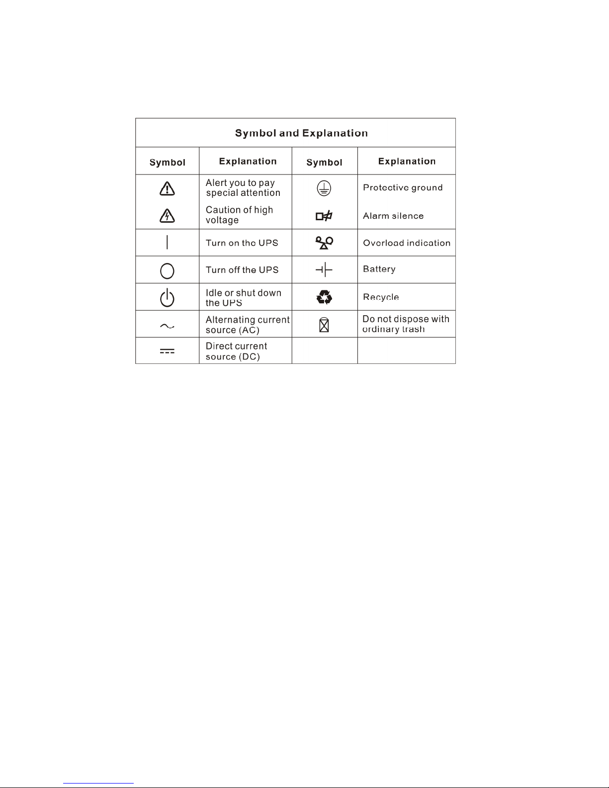
2. Description ofCommonlyUsedSymbols..........................................................................................4
3. Introduction 1K/2K/3K.........................................................................................................................5
4. SystemDescription.............................................................................................................................6
5. Connection and Operation.............................................................................................................7-10
5.1ConnectionandOperationfor1K(S)/2K(S)/3K(S)...................................................................7-10
6.TroubleShooting...............................................................................................................................11
7. Maintenance......................................................................................................................................12
7.1Operation.....................................................................................................................................12
7.2Storage........................................................................................................................................12
8.Technicaldata..............................................................................................................................13-14
8.1ElectricalSpecifications...............................................................................................................13
8.2OperatingEnvironment................................................................................................................13
8.3TypicalStoredEnergyTime(Typicalvaluesat25 Cinminutes:)..............................................13
8.4DimensionsandWeights.............................................................................................................14
9. Introduction 6K(S)/10K(S).................................................................................................................15
9.1Product Specification andPerformance.......................................................................................15
10.Installation..................................................................................................................................16-19
10.1UnpackingandInspection..........................................................................................................16
10.2InputandOutput PowerCordsandProtectiveEarthGroundInstallation..............................16-17
10.3Operating ProcedureforConnecting the Long Backup TimeModelUPS withthe External
Battery.......................................................................................................................................18
10.4ParallelOperation......................................................................................................................19
11.Operation and Operating Mode.................................................................................................20-24
11.1Operation..............................................................................................................................20-24
12.BatteryMaintenance.......................................................................................................................25
13.NotesforBatteryDisposaland BatteryReplacement................................................................26

14. TroubleShooting.............................................................................................................................27
15.Operating Modeforall Models..................................................................................................28-29
16. Communication Port.......................................................................................................................30
17.SoftwareforAllModels...................................................................................................................31
18.Appendix.....................................................................................................................................32-36
Appendix1 DisplayPanel(for6K(S)/10K(S))......................................................................32
Appendix2 TheCorrespondingForm of theLEDDisplayfor6K(S)/10K(S)...................................33
Appendix3 Back Panel...............................................................................................................35-36

1. Safetyand EMCinstructions
Pleasereadcarefullythefollowinguser manualandthesafetyinstructions
before installing the unit or using the unit!
1.1Installation
★Condensation mayoccurif the UPS ismoved directlyfromacoldtoawarmenvironment.
The UPS must be absolutelydrybeforebeing installed. Pleaseallowan acclimatization
timeof at least twohours.
★Donot install the UPS nearwaterorindampenvironment.
★Donot install the UPS whereit wouldbe exposed todirect sunlight ornearheat.
★Donot block ventilation openingsinthe UPSshousing.
★Donot connectappliancesoritemsof equipmentwhichwouldoverload theUPS (e.g.laser
printers, etc)tothe UPS outlet sockets.
Placecablesinsuchawaythat no one can step on ortripoverthem.
For1KVA/2KVA/3KVA
Socket-outletsand socketofbatteriesareearthed bythe inputpowercord,pleaseinsertthe
powercordintomainssocket beforeusing of UPS.
Connect the UPS onlytoan earthed shockproof socket outlet.
The building wiringsocketoutlet(shockproofsocketoutlet)mustbe easilyaccessibleto
closetothe UPS.
Thisisoperatorinstallable.
For6KVA/10KVA
UPS hasprovided earthed terminal, inthe finalinstalledsystemconfiguration, equipotential
earthbonding tothe externalUPS batterycabinets.
Anintegralsingleemergency switching devicewhichpreventsfurthersupplytotheload by
the UPS inanymode of operation shouldbe provided inthe building wiring installation.
Anappropriatedisconnectdeviceasshort-circuitbackupprotection shouldbe provided in
the building wiring installation.
Forthree-phaseequipmentconnectiontoanITpowersystem,afour-poledevicewhich
disconnectallphaseconductorsand the neutralconductorshouldbe provided inthe
building wiring installation.
Thisispermanentlyconnectedequipment,itmustbe installed byqualified maintenance
personnel.
Earthconnection essentialbeforeconnecting tothe building wiring terminal.

2
1. Safetyand EMCinstructions
1.2Operation
Donotdisconnectthe mainscableon the UPS orthe building wiring socket(grounded
shockproofsocket)during operation asthiswouldremovethe ground tothe UPS and ofall
connected loads.
The UPS outputsocketoroutputterminalblock maybe electricallylivedevenifthe UPS
systemisnot connected tothe building wiring terminal.
Inordertofullydisconnectthe UPS,firstpress the Standbybutton,thendisconnectthe
mainslead.
Ensurethat no liquidorotherforeign objectscan enterthe UPS.
The UPS can be operated byanyindividualswithno previousexperience.
1.3Maintenance, servicing and faults
The UPS operateswithhazardousvoltages.Repairsmaybe carried outonlybyqualified
maintenancepersonnel.
Caution-risk ofelectricshock.Even aftertheunitisdisconnected fromthe mainspower
supply(building wiring socket),componentsinside theUPS arestillconnected tothe battery
whicharepotentiallydangerous.
Beforecarryingoutanykindofserviceand/ormaintenance,disconnectthe batteries.
Verifythatno currentispresentand no hazardousvoltageexistsinthe capacitororBUS
capacitorterminals.
Batteriesmust be replaced onlybyqualified personnel.
Caution-riskofelectricshock.The batterycircuitisnotisolated fromthe inputvoltage.
Hazardousvoltagesmayoccurbetween the batteryterminalsand the ground. Verifythatno
voltage ispresent beforeservicing!
Batterieshaveahigh short-circuitcurrentand posearisk ofshock.Takeall precautionary
measuresspecified belowand anyothermeasuresnecessarywhen working withbatteries:
-removeall jewellery, wristwatches, ringsand othermetalobjects
-useonlytoolswithinsulated gripsand handles.
When changing batteries, replacewiththe samequantityand the sametype of batteries.
Donot attempt todisposeof batteriesbyburning them. It couldcauseexplosion.
Donotopen ordestroybatteries.effluentelectrolytecan causeinjurytothe skinandeyes.It
maybe toxic.
Pleasereplacethe fuseonlybyafuseof the sametype and of the sameamperage inorder
toavoidfirehazards.
Donot dismantlethe UPS, except the qualified maintenancepersonnel.

3
1. Safetyand EMCinstructions
1.4Transport
PleasetransporttheUPS onlyinthe originalpackaging (toprotectagainstshock and
impact).
1.5Storage
The UPS must be stockpiled inthe roomwhereit isventilated and dry.
1.6Standards
Onlythe unitswithCEmarkingsarecomplywiththe following standards:
For1KVA/2KVA/3KVA
*Safety
IEC/EN62040-1-1
*EMI
Conducted Emission...............................:IEC/EN50091-2 CLASS B
Radiated Emission..................................:IEC/EN50091-2 CLASS B
HarmonicCurrent....................................:IEC/EN61000-3-2
Voltage Fluctuation and Flicker...............:IEC/EN61000-3-3
*EMS
ESD........................................................:IEC/EN61000-4-2 Level4
RS..........................................................:IEC/EN61000-4-3 Level3
EFT.........................................................:IEC/EN61000-4-4 Level4
SURGE..................................................:IEC/EN61000-4-5 Level4
LowFrequency Signals.........................:IEC/EN61000-2-2
For6KVA/10KVA
*Safety
IEC/EN62040-1-1
*EMI
Conducted Emission.................................:IEC/EN50091-2 Current>25A
Radiated Emission....................................:IEC/EN50091-2 Current>25A
*EMS
ESD.......................................................:IEC/EN61000-4-2 Level4
RS.........................................................:IEC/EN61000-4-3 Level3
EFT........................................................:IEC/EN61000-4-4 Level4
SURGE.................................................:IEC/EN61000-4-5 Level4
LowFrequency Signals.........................:IEC/EN61000-2-2
Warning: Thisisaproduct forrestrictedsalesdistribution toinformed partners.
Installation restrictionsoradditionalmeasuresmaybe needed toprevent
disturbances.

4
2. Description ofcommonlyusedsymbols
Someorallofthefollowingsymbolsmaybe used inthismanual.Itisadvisabletofamiliarize
yourself withthemand understand theirmeaning:

5
3. Introduction 1K/2K/3K
ThisOn-Line-Seriesisan uninterruptiblepowersupplyincorporating double-converter
technology. It providesperfect protection specificallyforNovell, WindowsNTand UNIX
servers.
The double-converterprincipleeliminatesall mainspowerdisturbances. Arectifierconverts
the alternating current fromthe socket outlet todirect current. Thisdirect current chargesthe
batteriesand powersthe inverter. Onthe basisof thisDC voltage, the invertergeneratesa
sinusoidalACvoltage, whichpermanentlysuppliesthe loads.
Computersand peripheryarethuspowered entirelybythe mainsvoltage. Inthe event of
powerfailure, the maintenance-free batteriespowerthe inverter.
Thismanualcoversthe UPS listed asfollows. Pleaseconfirmwhetherit isthe modelyou
intend topurchasebyperforming avisualinspection ofthe ModelNo.on the rearpanelofthe
UPS.
S”Model:Longbackup time
Model No. Type Model No. Type
1K 1KS
2K 2KS
3K Standard 3KS Long backup time

6
4. System Description
Figure1:DisplayPanel
Switch Function
ON-Switch
Turnon UPS system:
Bypressingthe ON-Switch “I”the UPS systemisturned on.
Deactivateacousticalarm:
Bypressingthisswitchan acousticalarmcan bedeactivated.
OFF-Switch
When mainspowerisnormal, the UPS systemswitchestoStandbymode by
pressingOFF-Switch ““. It isthen switched toBypass and the inverterisoff.
At thismoment, the output socketsaresupplied withvoltageviathe bypass if
the mainspowerisavailable.
Display Function
LINELED
The green LINELEDlightsupifmainsvoltageisapplied tothe UPS input.
LINELEDblinks when the phaseand neutralconductorhavebeen reversed
at the input ofthe UPS system.
IfLINELEDand BATTERY-LEDlight up, the mainspowersupplyisout of
tolerance.
BATTERYLED The orange-coloured BATTERY-LEDlightsupwhen the mainspowerhas
failed and the inverterisbeingpowered bythe batteries.
BYPASS LED The orange-coloured BYPASS LEDlightsupwhen the UPS systemis
supplyingvoltageprovided bythe mainspowerviathe bypass.
INVERTERLED The green-coloured INVERTERLEDlightsupifthe UPS systemissupplying
voltageprovided bythe mainspowerviathe inverter.
FAULTLED The red FAULTLEDlightsupand an acousticwarningsignalisissued
continuouslywhen the UPS systemisinfault condition. Press the Standby
switchinordertoturnoffthe warningtone.
Display Function
LOADand
BATTERY
CAPACITYLEDs
TheseLEDsshowthe load of the UPS systemif the mainspowerisavailable
(normaloperation):
2nd LED: 96%-105%3rdLED: 71%-95%4thLED: 51%-70%
5thLED: 31%-50%6thLED: 0-30%
Inthe batteryoperation, the LEDsindicatethe capacityofthe batteries:
2nd LED: 0-25 %3rdLED: 26%-50 %4thLED: 51%-75 %
5thLED: 76%-95 %6thLED: 96%-100 %

7
5. Connection and Operation
5.1Connection and operation for1K(S)/ 2K(S)/ 3K(S)
1)Inspection: Inspect the packaging carton and itscontentsfordamage. Pleaseinformthe
transport agency immediatelyshouldyou find signsof damage.
Pleasekeep the packaging inasafeplaceforfutureuse.
Note:Please ensurethattheincoming feederisisolatedand securedtopreventit
frombeing switchedback on again.
2)Connection:
2.1)UPS Input Connection
If the UPS isconnected viathe powercord, pleaseuseapropersocket with
protection against electriccurrent, and payattention tothe capacityof the socket:
over10Afor1K(S)&2K, over16Afor2KS& 3K(S).
2.2)UPS Output Connection
The output of 1K(S)and 2KS(Non CE)aresocket-typesonly. Simplyplug the load
powercordtothe output socketstocompleteconnection.
ModelNo. OutputSocket(pcs)
Terminal Block
1K/1KS 4 Nil
2K 6 Nil
2KS 4(CE) 6(Non CE) Available(CE) Nil (Non CE)
3K/3KS 4(CE) 3(Non CE) Available
Besidesoutput sockets,2KS(CE)and 3K/3KS hasthe terminalblock availablefor
output aswell.The wiring configuration isshownasthe following procedure:
a)Removethe small coverof the terminalblock
b)UseAWG14 or2.1mm2wiresforwiring configuration
c)Upon completion of the wiring configuration, pleasecheck whetherthe wires
aresecurelyaffixed.
d)Put the small coverback tothe rearpanel.
The systemmaybe installed and wired onlybyqualified electriciansin
accordancewithapplicablesafetyregulations!
When installing the electricalwiring, pleasenotethe nominalamperage of
your incoming feeder

8
5. Connection and Operation
Figure2: Connection diagramof 2KS(CE)and 3K(S)
2.3)ComputerConnection:
Connectyourcomputertothe outletsocketsofthe UPS systemfollowing the above
diagram.
3)BatteryCharge: Fullycharge the batteriesofthe UPS systembyleaving the UPS system
connected tothe mainsfor1-2hours.You mayusethe UPS system
directlywithout charging it but the stored energytimemaybe shorter
than the nominalvalue specified.
4)TurnOnthe UPS:
4.1)Withutilitypowerconnecting:
Press “I”button continuouslyformorethan 1second toturnon the UPS.Then the
UPS will get intoself-test statusfirst. Afterhaving finishing the self-test, the UPS
willgetintotheinvertermode,at thistime,the UtilityPowerLED,InverterLED,and
Load and BatteryCapacityLEDswill light up.
4.2)Without utilitypowerconnecting:
Even though utilitypowerisconnected tothe UPS, the UPS still can be turned on
byjust simplypressing “I”button continuouslyformorethan 1second.Then the
UPS will get intoself-test statusfirst. Afterhaving finishing the self-test, the UPS
will get intothe invertermode, at thistime, BatteryLED, InverterLED, and Load
and BatteryCapacityLEDswill light up.
Note:Thedefaultsettingforbypass modeisnooutputafterUPS isconnectingutility
powerand breakeristurnedon. Thiscanbeconfiguredbymonitoring software.
5)Test Function:
Test the function of the UPS systembyeitherpressing the On-Switch “I”ordisconnecting
the input of the UPS systemfromthe powersupply.
Caution!
*Donot connect equipment whichwouldoverload the UPS system(e.g. laserprinters)

9
5. Connection and Operation
6)TurnOff the UPS:
6.1)InInverterMode:
Press “ “ button continuouslyformorethan 1second toturnoff the UPS.Then the
UPS will get intoself-test statusfirst. Afterhaving finished the self-test, the UPS will
getintobypass mode and the UtilityPowerLEDand Bypass LEDwill lightup.Atthis
time, the UPS might hasoutput. Disconnect the utilitypower toturnoff the output.
6.2)InBatteryMode:
Press “ “ button continuouslyformorethan 1second toturnoff the UPS.Then the
UPS will get intoself-test statusfirst. Afterhaving finished the self-test, the UPS will
be turned off completely.
7)AudibleAlarmMuteFunction:If the alarmistoo annoying inbatterymode,you may
press “I”button continuouslyformorethan 1second toclearit. Moreover,thealarmwill
be enabled when the batteryislowtoremind you toshutdownthe load soon.
8)Operation Procedureof ExternalBatteryforLong Backup timeModel(“S”Model)
The unitswithCEmarkings—
(1)Usethe batterypack withvoltage: 36VDC for1KS (3pcs of 12Vbatteries), 96VDC
for2KS/3KS (8pcs of 12Vbatteries). Connectionof batteriesmorethanorlessthan
required will causeabnormality
(2)One end of the externalbatterycordisaplug forconnecting the UPS and the other
end hasaplug forconnecting the userbatterycabinet
(3)Donot connecttheUPS toanyload yet. Then, connect thepowercordofthe UPS to
supplyutilitypowertothe UPS tomakethe UPS operateinutilitypowermode.
(4)Connect the plug of the externalbatterycordtothe externalbatterysocket on the
rearpanelof the UPS tocompletethe connection procedureand the UPS will start
tocharge the batterypack.
The unit without CEmarkings—
(1)Usethe batterypackwithvoltage:36Vdcfor1KS (3pcs of 12Vbatteries),96Vdcfor2
KS/ 3KS (8pcs of 12Vbatteries). Connection of batteriesmorethan orless than
required will causeabnormality.
(2)One endof theexternalbatterycordisaplugforconnectingthe UPS andtheotherend
has3(or2)open wiresforconnecting the batterypack.
(3)The batteryconnection procedureisveryimportant. Anyincompliancemayresultinthe
risk of electricshock.Therefore, the following stepsmust be strictlycomplied with.
(4)First connect inseriesthe batteriesof the pack toensureproperbatteryvoltage.
(5)Connect the externalbatterycordtothe batteryterminal(DO NOTconnect the battery
socket of the UPS first. Otherwise, it maycauseelectricshock). Connect the red wire
to.

0
5. Connection and Operation
(6)the "+"terminalof the battery.The black wireisconnected tothe "-"terminalof the
battery. (Note: the green/yellowwireisgrounded forprotection purpose.)
(7)Donotconnectthe UPS toanyloadyet. Then,connectthe powercordoftheUPS to
supplyutilitypowertothe UPS tomakethe UPS operation inutilitypowermode.
(8)Plug theexternalbatterycordtothe externalbatterysocketon therearpanelofthe
UPS tocompletetheconnectionprocedureandtheUPS willstart tocharge the battery
pack.
TheCaution!
The output socketsof the UPS systemmaystill be electricallyliveeven ifthe power
supplysystemhasbeen disconnected orthe Bypass switchison “OFF”position.

6. TroubleShooting
If the UPS systemdoesnotoperatecorrectly,pleaseattempttosolvethe problemusing the
tablebelow.
Problem Possiblecause Remedy
No indication, no warning tone even
though systemisconnected to
mainspowersupply
No input voltage Check building wiring socketoutletand input
cable.
LINELEDblinks Phaseand neutral
conductorat input ofUPS
systemarereversed
Rotatemainspowersocketby180°orconnect
UPS system.
LINE-LEDblinksand
BATTERY-LEDlightsup
Input powerand/or
frequency areout of
tolerance
Check input powersourceand informdealerif
necessary
LINEand BYPASS LEDlight up
even though the powersupplyis
available
Inverternot switched on Press On-Switch “I”
INVERTERLEDlightsup, and
audiblealarmsounding every 1
beep inevery 4seconds
Mainspowersupplyhas
failed
Switching tobattery mode automatically.
When audiblealarmsounding every second,
battery isalmost empty.
FAULT LEDlights, warning tone
onceasecond
Overload RemoveloadsofUPS output.
FAULT-LEDlightsup, permanent
warning tone
UPS fault Notifydealer!!
Emergency supplyperiod shorter
than nominalvalue
Batteriesnotfullycharged
/ batteriesdefect
Charge the batteriesforat least
1-2hoursand then check capacity. Ifthe
problemstill persists, consult yourdealer.
FAULTLEDlights, BATTERY-LED
blinks, warning tone onceasecond
ChargerorBatteries
damaged
Notifydealer!!
Pleasehavethe following information at hand beforecalling the After-SalesService
Department:
1.Modelnumber, serialnumber
2.Dateon whichthe problemoccurred
3.Detailed description of the problem

2
7. Maintenance
7.1Operation
The UPS systemcontainsno user-serviceableparts.If the batteryservicelife(3-5
yearsat 25°Cambient temperature)hasbeen exceeded, the batteriesmust be replaced.
Inthiscasepleasecontact yourdealer.
7.2Storage
If the batteriesarestored intemperateclimaticzones,theyshouldbe charged everythree
monthsfor1-2hours.You shouldshorten the charging intervalstotwomonthsatlocations
subject tohigh temperatures.

3
8. Technical Data
8.1Electrical specifications
INPUT
ModelNo. 1K(S) 2K 2KS 3K(S)
Phase Single
Frequency (46~54)Hz
Current(A) 7A 9A 12A 16A
OUTPUT
ModelNo. 1K(S) 2K(S) 3K(S)
Powerrating 1kVA/0.7kW 2kVA/1.4kW 3kVA/2.1kW
Voltage 220/230/240×(1士2%)VAC
Frequency 50Hz±0.2Hz(Batterymode)
Waveform sinusoidal
BATTERIES
ModelNo. 1K 2K 3K
Numberand type
3×12V7.2Ah 8×12V7.2Ah 8×12V7.2Ah
8.2Operating Environment
AmbientTemperature 0oCto40oC
Operating humidity <95%
Altitude <1000m
Storage temperature 0oC~40oC
8.3Typical storedenergytime(Typical values at25 Cinminutes:)
ModelNo. 100 %Load 50 %Load
1K 5 14
2K 9 21
3K 5 15

4
8. Technical Data
8.4Dimensionsand weights
ModelNo. DimensionsWxDxH(mm) Net Weight kg
1K 145X400X220 14
1KS 145X400X220 7
2K 192X460X340 34.5
2KS 192X460X340 15
3K 192X460X340 35.5
3KS 192X460X340 16

5
9. Introduction 6K(S)/10K(S)
9.1ProductSpecification and Performance
1)General Specification
Model 6K 6KS 10K 10KS
PowerRating 6KVA/4.2KW 6KVA/4.2KW 10KVA/7KW 10KVA/7KW
Frequency (Hz) 50 50 50 50
Voltage (176-276)VAC (176-276)VAC (176-276)VAC (176-276)VAC
Input Current 31Amax. 31Amax. 50Amax 50Amax.
Voltage 240VDC 240VDC 240VDC 240VDC
Battery
Current 24Amax 24Amax 40Amax 40Amax
Voltage 220VAC 220VAC 220VAC 220VAC
Output
Current 27A 27A 45A 45A
Dimension (WxDxH)mm
260x570x717 260x570x717 260x570x717 260x570x717
Weight (kg) 90 35 93 38
2)Electrical Performance Input
Model Voltage Frequency PowerFactor
6K(S)/10K(S) Single-phase 46Hz-54Hz >0.98 (Full load)
Output
Voltage
Regulation
Power
Factor Frequency
tolerance. Distortion
Overload capacity
Currentcrest
ratio
±1% 0.7lag
Synchronized
46-54Hzin
Line mode
(ACmode)
±0.1%of
normal
frequency in
Batterymode
THD<2%
Full load
(Linear
Load)
105%-130%load
transferstobypass
mode after10 minutes
>130%load transfers
tobypass mode after1
second and shutdown
the output after1
minute
3:1
maximum
3)OperatingEnvironment
Temperature Humidity Altitude Storage temperature
0°C-40°C <95% <1000m 0°C-40°
Note: if the UPS isinstalled orused inaplacewherethe altitude isabovethan
1000m, the output powermust be derated inuse, pleaserefertothe following:
Altitude (M) 1000
1500
2000
2500
3000
3500
4000
4500
5000
Derating Power
100%
95%
91%
86%
82%
78%
74%
70%
67%

6
10. Installation
10.1Unpacking and Inspection
1)Unpack the packaging and check the package contents.The shipping package
contains:
lAUPS
lAusermanual
lAcommunication cable
lAbatterycable(for6KS/10KS only)
2)Inspect the appearanceof the UPS tosee if thereisanydamage during
transportation. Donot turnon the unitand notifythe carrierand dealerimmediatelyif
thereisanydamage orlacking of someparts.
10.2Inputand outputpowercordsand protective earthground installation
1.Notes forinstallation
1)The UPS must be installed inalocation withgood ventilation, farawayfromwater,
inflammablegasand corrosiveagents.
2)Ensurethe airventson the front and rearof the UPS arenot blocked.Allowat least
0.5mof spaceon eachside.
3)Condensation towaterdropsmayoccurif the UPS isunpacked inaverylow
temperatureenvironment. Inthiscaseit isnecessarytowait until the UPS isfully
dried inside out beforeproceeding installation and use. Otherwisetherearehazards
of electricshock.
2.Installation
Installation and wiring must be performed inaccordancewiththe localelectriccode
and the following instructionsbyprofessionalpersonnel.
Forsafety, pleasecut off the mainspowerswitchbeforeinstallation.The battery
breakeralsoneedstobe cut off if it isalong backup timemodel(“S”model).
1)Open theterminalblock coverlocated ontherearpanelofthe UPS, pleaserefer
tothe appearancediagram.
2)For6K(S)UPS, it isrecommended toselect the UL1015 10AWG(6mm2)wireor
otherinsulated wirewhichcomplieswithAWG Standardforthe UPS input and
output wirings.
3)For10K(S), it isrecommended toselect the UL1015 8AWG(10mm2)wireor
otherinsulated wirewhichcomplieswithAWG Standardforthe UPS input and
output wirings.

7
10. Installation
Note: Donot usethe wall receptacleasthe input powersourceforthe UPS, asits
rated currentisless than theUPSsmaximuminputcurrent. Otherwisethe receptacle
maybe burned and destroyed.
4)Connect the input and output wirestothe corresponding input and output
terminalsaccording tothe following diagram.
Note: you must makesurethat the input and output wiresand the input and output
terminalsareconnected tightly.
5)The protectiveearthground wirereferstothe wireconnection between the
equipment whichconsumeselectricequipment and the ground wire.The wire
diameterof protectiveearthground wireshouldbe at least asabovementioned
foreachmodeland green wireorgreen wirewithyellowribbon wireisused.
6)Afterhaving completed the installation, makesurethe wiring iscorrect.
7)Pleaseinstall the leakcurrentprotectivebreakeratthe outputpowerdistribution
panelof the UPS if necessary.
8)Toconnect the load withthe UPS, pleaseturnoff all the loadsfirst, then perform
the connection and finallyturnon the loadsone byone.
9)Nomatterthe UPS isconnected totheutilitypowerornot,theoutput oftheUPS
mayhaveelectricity.The partsinside the unit maystill havehazardousvoltage
afterturning off the UPS.Tomakethe UPS haveno output, poweroff the UPS,
and then disconnect the utilitypowersupply.
10)Suggest charging the batteriesfor8hoursbeforeuse.Afterconnection,turnthe
inputbreakerinthe “ON”position,theUPS willchargethebatteriesautomatically.
You can alsousethe UPS immediatelywithout charging the batteriesfirst, but
the backup timemaybe less than the standardvalue.
11)If it isnecessarytoconnect the inductanceload suchasamonitororalaser
printertotheUPS,the start-up powershouldbe used forcalculatingthe capacity
of the UPS, asitsstart-up powerconsumption istoo bigwhen it isstarted.
Input and outputTerminalBlock wiring diagramof
6K(S)/10K(S)
This manual suits for next models
6
Table of contents
Other Atek UPS manuals