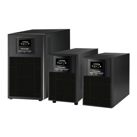
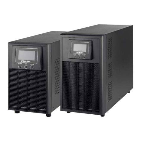
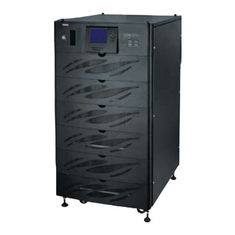
MODEL
PWR9010 PWR9015 PWR9020 PWR9030 PWR9040 PWR9060 PWR9080 PWR9100
CAPACITY
10KVA 15KVA 20KVA 30KVA 40KVA 60KVA 80KVA 100KVA
POWER
8KW 12KW 16KW 24KW 32KW 48KW 64KW 80KW
INPUT
Phase
Voltage Range
Frequency
Rectier
OUTPUT
Rated Voltage
Phase Voltage Setting
Phase
Frequency
Power Factor
Wave Form
Crest Factor
Transient Response
Range of Phase Lock
Total Harmonic Distortion
Short Circuit Current
Overload Capacity
BATTERY
Battery
DC Voltage
384VDC 432VDC 480VDC
BYPASS
Type
Input Phase
Input Voltage Range
Input Frequency Range
Transfer Time
Overload Capacity (10 min)
170% 180% 170% 170% 170% 140% 130% 125%
SYSTEM
Remote Signaling
Dry contact (battery low, battery discharging, bypass/ fault); output 12Vdc/80mA
Remote Control
EPO and bypass
Communication Interface
RS232 ( SNMP, modem optional )
Running Temperature
Relative Humidity
Less than 95% (without condensing)
Altitude
1000m output nominal power (with increase of 100m, it will reduce output of 1%) max 4000m
Noise at 1 M
Less than 60 dB
Inverter Efciency
92% 93%
Degree of Protection
IP20
Applicable Standards
EN50091-1-EMC EN50091-2liv.A
Isolation transformer
Harmonic wave suppression lter
Parallel modules up to six units
Net/Gross weight (Kg)
223/280 260/317 260/317 336/393 351/408 497/574 556/633 756/856
PWR9120
120KVA
96KW
125%
901/1001
PWR9160
160KVA
128KW
125%
1300/1400
PWR9200
200KVA
160KW
125%
1350/1450
Unit Dimension (W×D×H)mm
550 × 725 × 1220 800 × 745 × 1400 1070 × 745 × 1400
Packing Dimension (W×D×H)mm
660 × 855 × 1425 880 × 945 × 1585 1254 × 875 × 1585
1420 × 745 × 1810
1520 × 880 × 2000
3 phase 4 wire + GND
±20%
45 – 65Hz
3 phase 6 pulses
380/400/415V optional
200 - 244VAC (control panel )
3 phase 4 wire and ground
0.8
Sine wave
3:1
±5%, 10ms
With synchronization: ±0.05%
Without synchronization: ±2% (settable ±1% on the control panel)
3% ( linear load)
200% for 0.1s
110% /125% /150% rated current 300 min/ 10min /1min
Sealed lead acid maintenance free
Static state + manual maintenance bypass
3 phase 4 wire + GND
15% ~ 25% front control panel selectable
±1% ~ ±5% front control panel selectable
Inverter / bypass transfer switch time(overload): 0ms
Inverter / bypass transfer switch time (fault inverter) 1ms
50/60 Hz ±0.05%
0-40°C
Option
Product Specications
20
*The infomation issued within this publication is accurate at the time of printing and shall be subjected to changes at the discretion of the company without any prior notice. As we seek constant improvement in our product development, we shall not be held liable for non-compliance with the contents and images
stated unless otherwise conrmed by us. All copyrights reserved.
