Package Contents
1 VK102 Tabletop Kit (EU, 2-Gang)
4 anchors
4 M4x18 screws
2 M3x5 screws
6 M3x8 screws
1 user instructions
Contents
Hardware Overview .................................................................................... 3
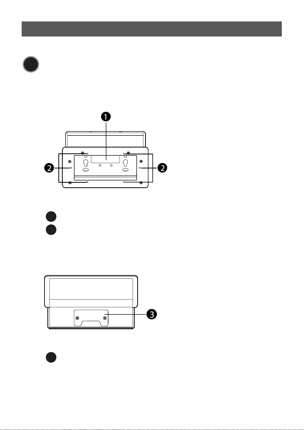
Front View .......................................................................................... 3
Rear View ........................................................................................... 3
Bottom View ....................................................................................... 4
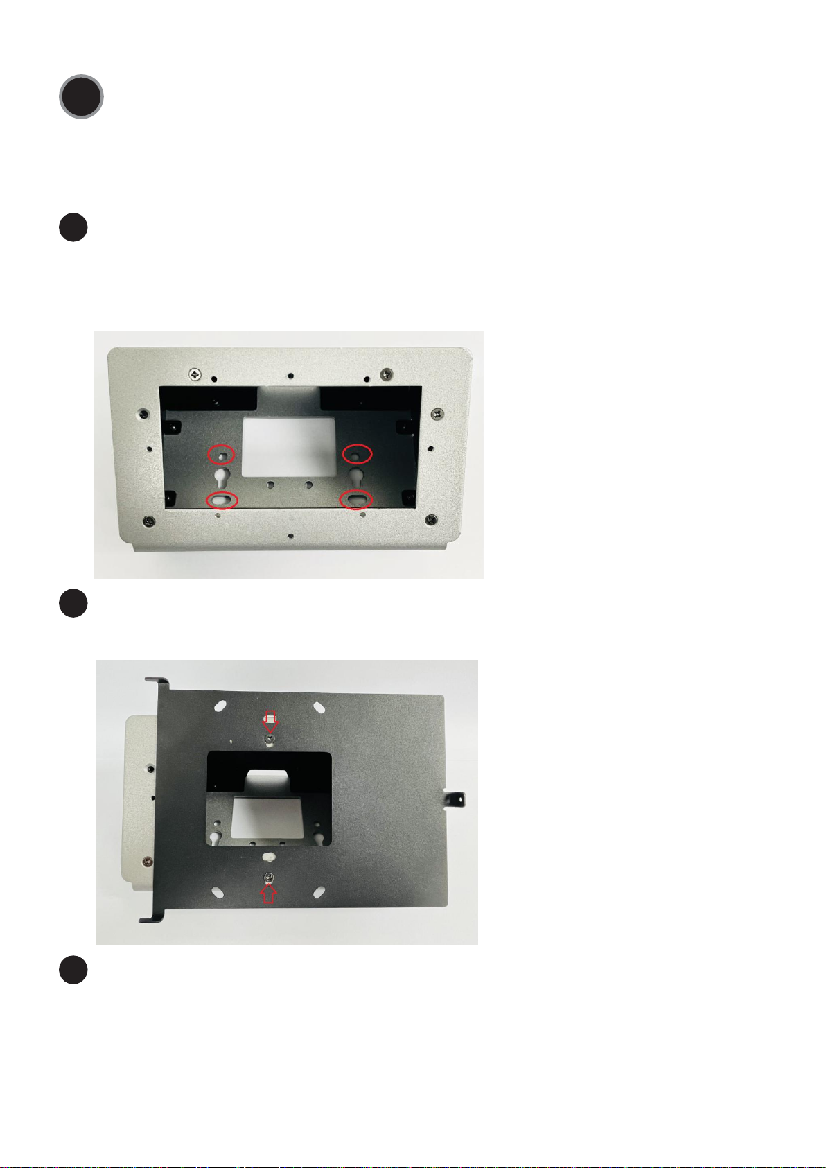
Installing an ATEN Control Pad / Keypad .................................................... 5
Desktop Mount ................................................................................... 5
Wall Mount ......................................................................................... 6
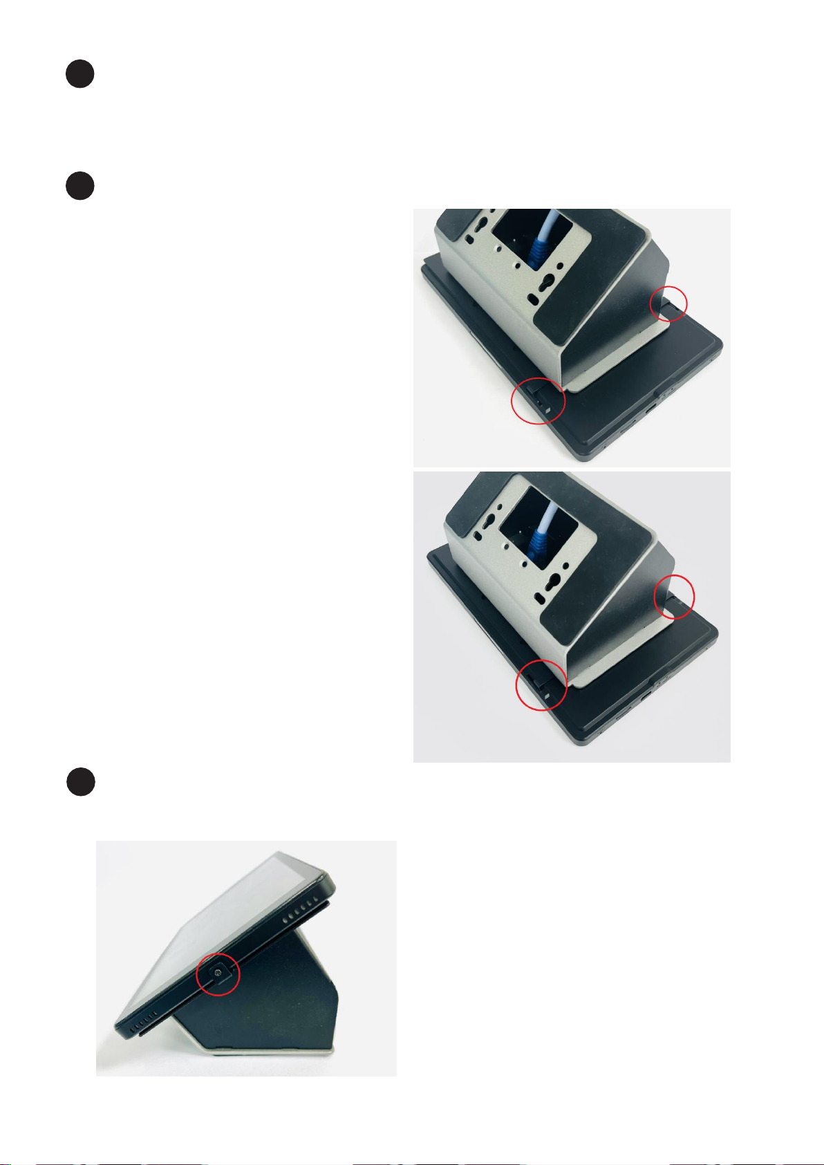
Installing an ATEN Touch panel (VK320)..................................................... 7
Desktop Mount ................................................................................... 7
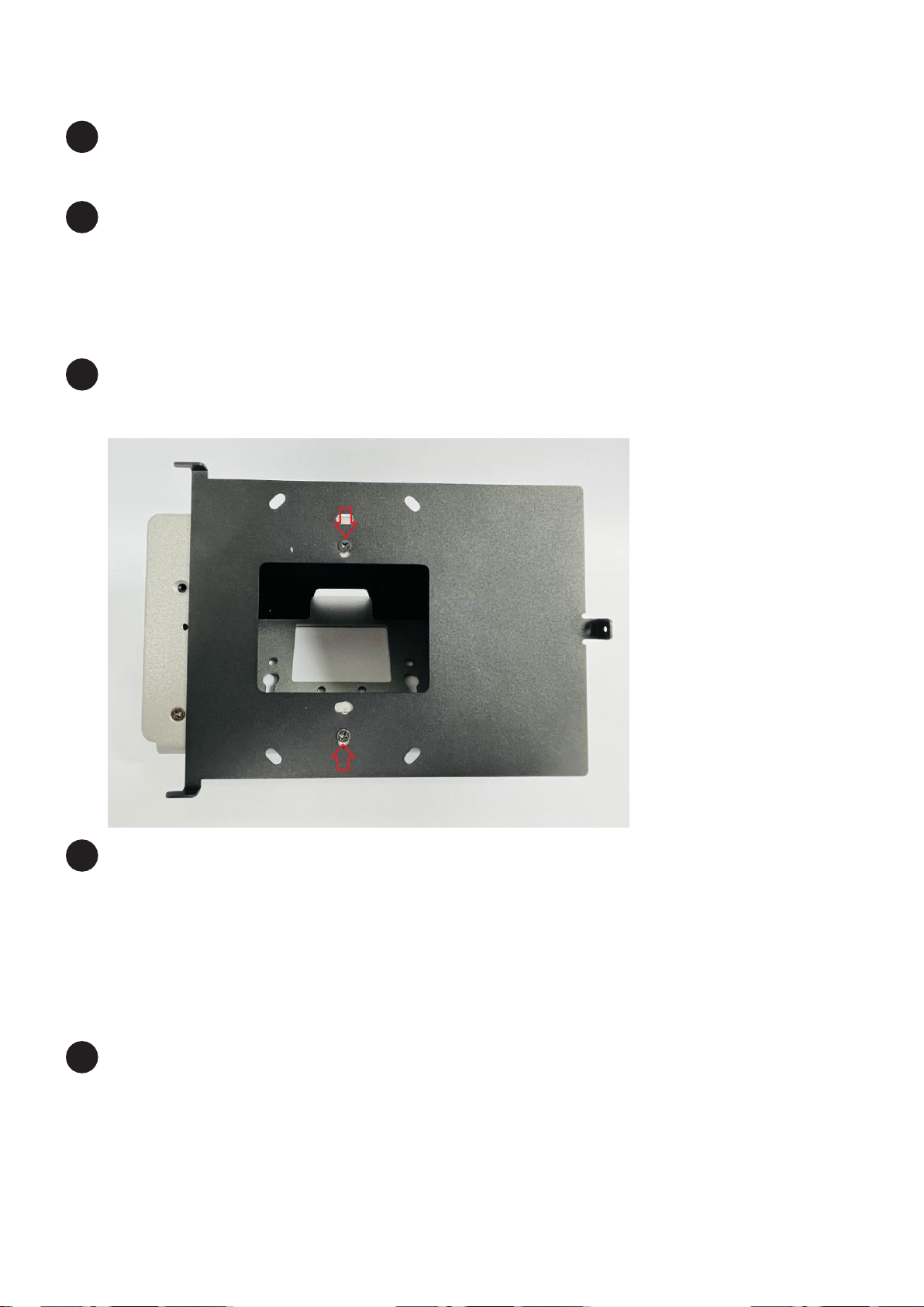
Wall Mount ......................................................................................... 9
Installing an ATEN HDMI & VGA HDBaseT Transmitter (VE2812AEUT) ....... 11
Desktop Mount ................................................................................. 11
Wall Mount ....................................................................................... 13
Scan for more information
Product Page User Manual
Support and Documentation Notice
All information, documentation, firmware, software
utilities, and specifications contained in this package
are subject to change without prior notification by the
manufacturer.
To reduce the environmental impact of our products,
ATEN documentation and software can be found online
at http://www.aten.com/download/
Technical Support
www.aten.com/support