8
F
Allgemeine Gebrauchs-und
Warnhinweise
1.
Die zulässige Dachlast (= Gewicht des
Dachträgers + Zubehör + Beladung) des
Fahrzeugherstellers oder eine
gegebenenfalls niedrigere Lastwertangabe
des Trägerherstellers dürfen nicht
überschritten werden.
2.
Zur Sicherheit sind die
Schraubverbindungen und die
Spannbänder vor jeder Fahrt auf
Beschädigungen, festen Halt und
ordnungsgemäßen Sitz zu prüfen und ggf.
nachzuziehen (schadhafte Gurte sofort
ersetzen). Nach kurzer Fahrtstrecke
anhalten und Schraubverbindungen und
Spannbänder auf einwandfreien Sitz
kontrollieren. Diese Kontrollen sind in
regelmäßigen Abständen, abhängig auch
von der Beschaffenheit der Fahrbahn, vom
Fahrzeugführer zu wiederholen.
3.
Das Fahrverhalten ändert sich bei
montiertem und beladenem Dachträger.
Dies gilt insbesondere für die
Seitenwindempfindlichkeit, das Kurven-
und Bremsverhalten. Zusätzlich sollte dem
durch Dachträgersystem und Ladung
verursachten, veränderten Fahr- und
Bremsverhalten durch angepaßte
Geschwindigkeit Rechnung getragen
werden.
4.
Vorsicht bei Unterführungen, Durchfahrten
und Garageneinfahrten.
5.
Aus Gründen der Sicherheit gegenüber
anderen Verkehrsteilnehmern und zur
Vermeidung unnötigen Energieverbrauchs,
ist der Dachträger bei Nichtbenutzung vom
Fahrzeug abzunehmen.
6.
Fahrräder nicht in Planen einpacken.
Kindersitze und verlierbares
Fahrradzubehör demontieren.
7.
Fahrradteile, z.B. Lenker oder Pedale
dürfen nicht über den Umriß des
Fahrzeuges hinausragen.
8.
Technische Änderungen vorbehalten.
GB
D
Instructions générales
d’utilisation et
avertissements
1.
La charge admissible sur le toit (= poids
du porte-bagages + accessoires +
chargement) indiquée par le constructeur
du véhicule ou, le cas échéant, si elle est
plus petite, celle du constructeur du porte-
bagages ne doit pas être dépassée.
2.
Pour votre sécurité, vérifier avant chaque
départ que les vis et les sangles de fixation
ne sont pas endommagées et qu’elles sont
serrées à fond et bien ajustées, et les
resserrer le cas échéant (les sangles de
fixation endommagées doivent
immédiatement être remplacées). Arrêter
après un bref parcours et vérifier le bon
serrage des vis et des sangles. Le
conducteur du véhicule doit répéter ces
contrôles en fonction de la nature de la
route à intervalles réguliers.
3.
Lorsque le porte-bagages est monté et
chargé, le comportement de conduite du
véhicule est modifié, et ceci notamment en
ce qui concerne sa sensibilité au vent
latéral ainsi que sa tenue en virage et son
comportement au freinage. Il faut tenir
compte de ce comportement différent de
conduite et de freinage dû au montage du
porte-bagages et au chargement de ce
dernier en adaptant la vitesse en
conséquence.
4.
Attention aux passages à hauteur et
largeur limitées et aux entrées de garage.
5.
En cas de non-utilisation, le porte-bagages
doit être démonté du véhicule par souci de
sécurité a l'égard des autres usagers de la
route et pour éviter une consommation
d'essence inutile.
6.
Ne pas bâcher les vélos.
Démonter les sièges pour enfants et tous
les accessoires des vélos qui risquent de
tomber pendant le trajet.
7.
Les éléments des vélos tels que les
guidons ou les pédales ne doivent pas
dépasser la largeur du véhicule.
8.
Sous réserve de modifications techniques.
General user information
and safety instructions
1.
The admissible roof load (= weight of the
roof rack + accessories + load) indicated by
the car manufacturer or, where applicable,
lower maximum loads indicated by the
manufacturer of the roof rack are not to be
exceeded.
2.
For safety reasons, the screws and straps
are to be checked before travelling to
make sure they are firmly secured and free
from damage. If necessary, the screws and
straps are to be tightened (damaged
straps are to be replaced immediately).
Always stop the vehicle after a short
distance and check the screws and straps
once again to ensure that they are still
firmly tightened. These checks are to be
carried out by the driver at regular
intervals according to the condition of the
road surface.
3.
The road behaviour of the vehicle changes
after the roof rack has been installed and
loaded. This applies in particular to the
vehicle's crosswind sensitivity, cornering
ability and brake reaction. Make sure to
travel at a safe speed to take account of
the changes in the vehicle's road
behaviour and brake action caused by the
roof rack and load.
4.
Utmost caution is advised when driving
through underpasses, passages and
garage entrances.
5.
For the safety of other road users and in
order to ensure fuel economy, remove the
roof rack during periods in which it
remains out of use.
6.
Do not wrap the bicycles in canvas covers.
Remove child carrier seats and bicycle
accessories that may easily fall off.
7.
Bicycle parts such as handlebars or pedals
must not project from the contours of the
car body.
8.
We reserve the right to make technical
changes.
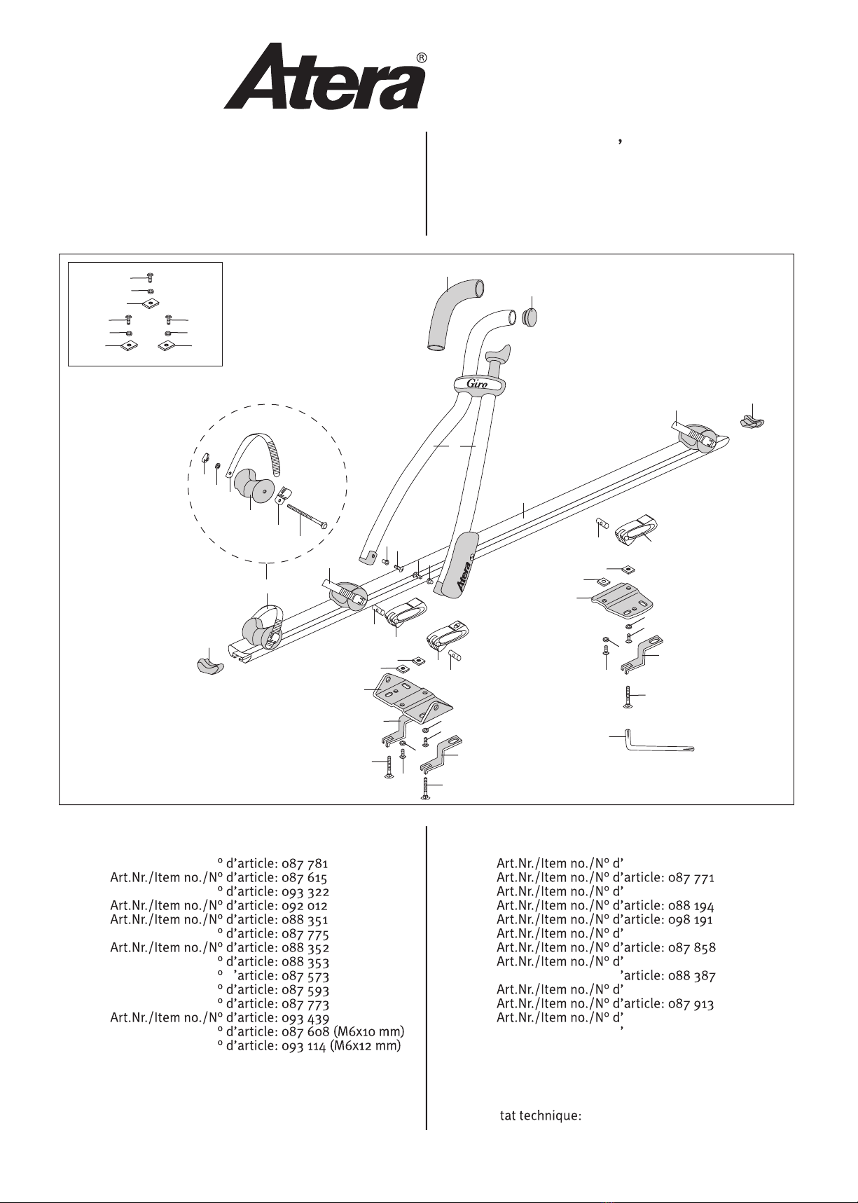
GIRO
Art.-Nr./Art. no./N° d’article: 082 216