Manitou DORADO EXPERT 37MM User manual

DORADO EXPERT 37MM SERVICE GUIDE

3
DORADO EXPERT 37MM SERVICE GUIDE
This manual is intended to guide the user through basic service of Manitou
Dorado Expert 37mm front forks. We highly suggest the service on these forks
be performed by an experienced suspension mechanic. Service is supported by
the identication of common parts and assemblies that have been assembled into
Service Kits. The purpose of this manual will be to describe conditions that may
drive the need for service and to provide installation instructions for the kits.
Please read through the manual carefully before beginning the service of your
fork. Having a basic understanding of the tasks you are about to perform will
assist you greatly in the disassembly and re-assembly of your fork.
Please read through the required tools page and be sure you have all of the items
you will need for the service of your fork. The 50 hour service only requires the
dust wiper seals and lubricants to be replaced. The complete 200 hour service
requires all O-rings and seals shown in this guide to be replaced.
For any assistance with the service of your Dorado Expert please contact our
Technical Service Department at 888-686-3472 and email them at
techsupport@hayesbicycle.com.
INTRODUCTION
We highly recommend that service be performed by a certied bicycle mechanic.
Failure to follow instructions presented in this manual could lead to serious injury
or death. Any questions about the servicing of this fork or the manual itself
should be directed to Hayes Customer Support at:
WARNING
! !
Hayes
Bicycle
USA
5800 W Donges Bay Road Mequon WI 53092
Phone: 888.686.3472
Email: techsupport@hayesbicycle.com
Hayes
Bicycle
Europe
Dirnismaning 20 a 85748 Garching (b. Munich) Germany
Phone: +49 89 203237450
Email: techsupportEU@hayesbicycle.com
Hayes
Bicycle
Asia
16F, No. 37, Sec. 3 Mincyuan E. Rd. Zhongshan District
Taipei City 10476 Taiwan ROC
Phone: 886-2-2518-1108
5800 W Donges Bay Rd
Mequon, WI 53092
manitoumtb.com
888.686.3472
Support: manitoumtb.com/support
MANITOU
For full warranty information please
visit hayesbicycle.com/warranty
WARRANTY

4 5
DORADO EXPERT 37MM SERVICE GUIDE DORADO EXPERT 37MM SERVICE GUIDE
table of contents
SECTION PAGE NUMBER
Tools And Materials 5
Damping Leg Service Disassembly 6
Damping Leg Service Assembly 11
Spring Leg Service Disassembly 16
Spring Leg Service Assembly 19
Dust & Oil Seal Replacement 22
Travel Change 24
Exploded View, Parts List, & Torque Table 25
O-Ring Placement Diagram & Table 28
tools and materials
Below is a list of tools that will be used in the complete service of a Dorado fork:
• Dorado Complete Rebuild Kit – Manitou Part number 141-38361-K001 (Needed for
200 hour complete service)
• Dorado 37mm Seal Kit - Manitou Part Number 141-38380-K019 (Needed for 50 hour
basic service)
• Dorado Clamp Blocks – Manitou Part Number 172-31464
• 34mm and 37mm Seal Press – Manitou Part Number 172-37540-K002
• 5wt Maxima Fork oil - Manitou part number 85-0023
• Manitou 5w40 Semi-Bath Oil - Manitou part number 85-0022
• Slickoleum™ Grease - Manitou part number 141-33604-K001
• Torque Wrench
• 12mm Combination Wrench
• 13mm Combination Wrench
• 22mm Combination Wrench
• 22mm Crow’s Foot
• 2mm Allen Wrench
• 2.5mm Allen Wrench
• 5mm Allen Wrench
• 6mm Allen Wrench
• 24mm at ground Socket with ratchet
• 26mm Socket
• 16 notch Bottom Bracket Tool
• Cassette Tool (only needed for Pro fork IRT removal)
• Small Flat Blade Screwdriver
• Snap-ring Pliers
• Pick or similar tool for removing O-rings
• Blue Loctite
6 7
DORADO EXPERT 37MM SERVICE GUIDE DORADO EXPERT 37MM SERVICE GUIDE
1 4
Loosen the damping leg top
cap using a 16 notch Bottom
Bracket Tool. It helps if the leg is
still clamped in the lower crown
assembly while breaking the top
cap loose (be sure the upper
crown is loosened, you only
want the lower tightened when
breaking loose the top cap).
Only loosen the top cap at this
point. Do not remove it.
2
Loosen the pinch bolts on the
lower crown and remove the
damping leg from the fork. You
will need to remove the frame
bumpers to do so. Put them
in a safe place so you do not
misplace them.
Tip: The ends of the Dorado sag
guide can be used to spread
the clamps apart and aid in leg
removal.
3
DAMPING LEG Disassembly DAMPING LEG Disassembly
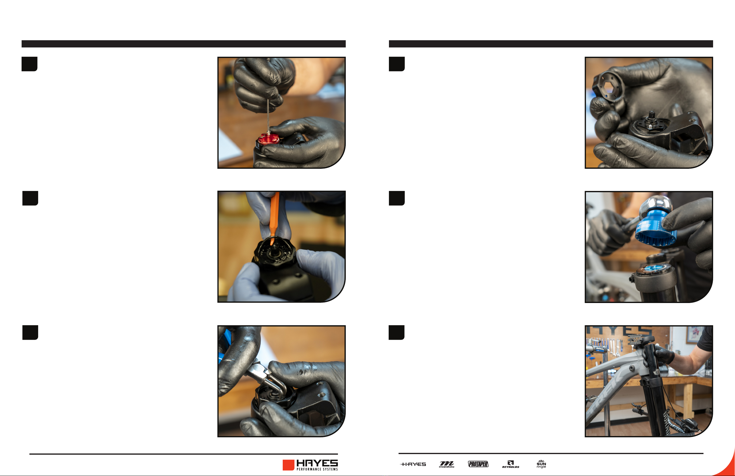
Orient the fork with the knobs
facing up. Using a 2mm Allen
wrench, remove the TPC+
adjuster knob.
Remove O-ring and be sure you
capture the 2 detent balls and
springs under the knob.
Next you will remove the High
Speed adjuster knob. Remove
the c-clip that holds the knob
on using a snap ring pliers or
similar tool.
Once the c-clip is removed pull
the knob up. Be sure to capture
the O-ring, 2 detent balls and
springs under the knob.
5
6
8 9
DORADO EXPERT 37MM SERVICE GUIDE DORADO EXPERT 37MM SERVICE GUIDE
DAMPING LEG Disassembly DAMPING LEG Disassembly
10
11
12
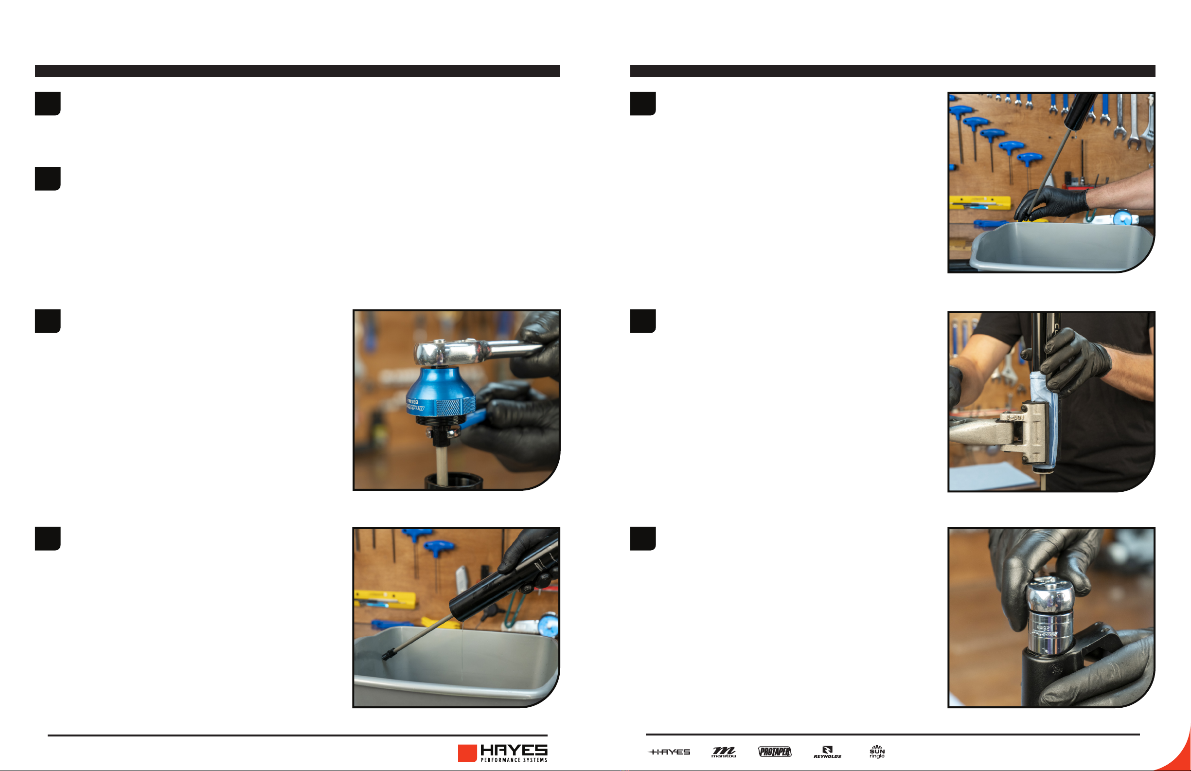
Remove the damping cartridge
from the inner leg using a
26mm socket.
13
8
Wrap the inner leg in a rag and
lightly clamp it into a bike stand
with the rebound shaft pointing
down towards the oor.
9You will now remove the top cap
from the rebound shaft. Place
a 12mm wrench on the ats of
the rebound shaft and use a
16 notch Bottom Bracket Tool
to unthread the top cap from
the shaft. Once the top cap is
unthreaded, remove the rebound
knob from the top cap.
Remove the fork leg from the
bike stand and pour the oil out of
the leg. Slide the inner leg out of
the outer leg and leave the outer
leg to drain in a drainage pan.
7Holding the inner leg over a
drainage pan, stroke the rebound
shaft several times to drain the
rest of the oil from the inner leg.
Remove the top cap from the fork leg using a 16 notch Bottom Bracket
Tool. The top cap is still attached to the rebound shaft at this point.
Clamp the upper sleeve of the fork in bike stand.
10 11
DORADO EXPERT 37MM SERVICE GUIDE DORADO EXPERT 37MM SERVICE GUIDE
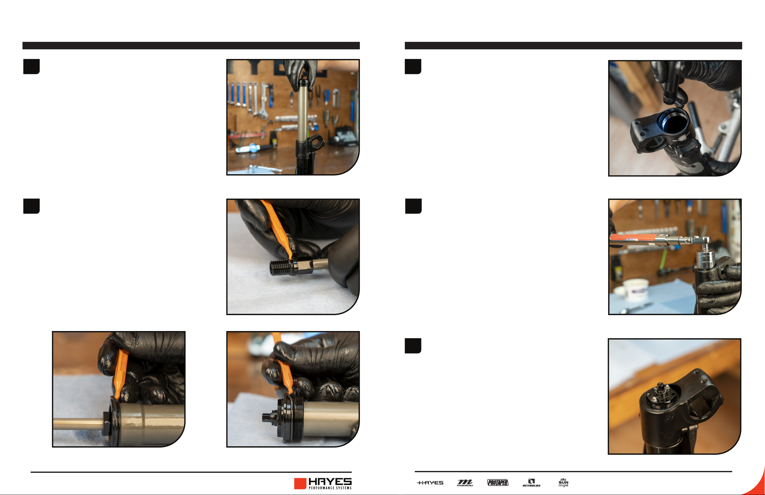
Replace the following O-rings on
the rebound damper assembly.
A. O-ring #100-012 - This is the
O-ring above the threads on the end of
the damper assembly.
B. O-ring #100-122 - This is the larger
O-ring on the damper end cap.
C. O-ring # 100-026 - This is the O-ring that
is around the outside of the compression
assembly top cap.
15
14
DAMPING LEG Disassembly
1Inspect the inner and outer
damper tubes and be sure
they are free from debris and
contaminants.
2
3
Apply a small amount of
Slickoleum grease to the O-ring
installed on the damper end cap.
Install the assembly in the inner
leg by sliding it into the bottom
of the leg. Use a 26mm socket to
tighten it into the leg. Tighten to
6.8-9 Nm (60-80 in lb).
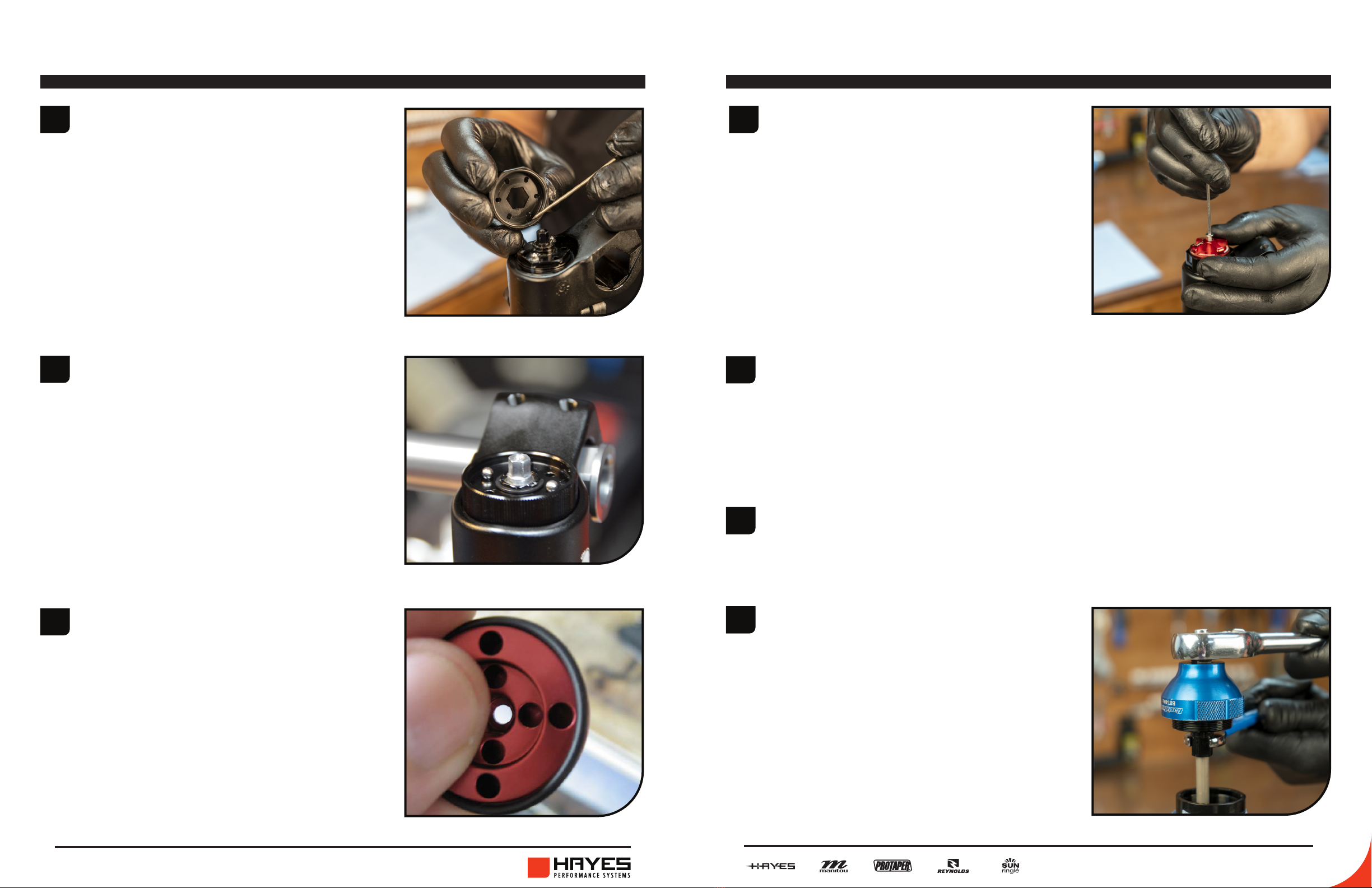
Insert the detent springs into
opposite holes in the end cap
and place the detent balls on top
of the springs. To hold the detent
balls in place on the spring use a
small dab of grease.
DAMPING LEG assembly
A
CB
TIP: You can also refer to the O-ring diagram on pages 28-29.
Pull the damping cartridge
completely out of the inner leg.
12 13
DORADO EXPERT 37MM SERVICE GUIDE DORADO EXPERT 37MM SERVICE GUIDE
DAMPING LEG assembly
7Install the TPC+ adjuster knob
onto the end cap and secure
with the 2mm screw.
5
6
Insert the springs into opposite
holes on the TPC+ adjuster knob
and then place the detent balls
in the corresponding holes of the
high speed adjuster knob.
Place O-ring # 100-024 around
the TPC+ knob and apply a
small amount of grease to it.
DAMPING LEG assembly
10 Install the top cap onto the end
of the rebound shaft. Use a 16
notch Bottom Bracket Tool and a
12mm wrench to tighten to the
proper torque of 6.8-9.0 N m
(60-80 in lb).
9Replace O-ring # 100-027 on the top cap.
8Replace the oil and dust seals on the outer leg following the directions on
pages 22-23. Inspect the inside of the outer leg and the outside of the
inner leg and be sure they are free from debris and contaminants. Lube the
oil seal and dust wiper on the outer leg with a small amount of Slickoleum
grease. Slide the inner leg into the outer leg and clamp into the bike stand.
4Install the high speed adjuster onto
the end cap. Be sure that O-ring
# 100-025 below the adjuster is
in place and greased. Secure the
adjuster with the c-clip (retaining
ring pliers are recommended for
use during installation).
14 15
DORADO EXPERT 37MM SERVICE GUIDE DORADO EXPERT 37MM SERVICE GUIDE
DAMPING LEG assembly DAMPING LEG assembly
13
14
After you have properly set the oil height fully extend the inner leg and
tighten down the top cap using a 16 notch Bottom Bracket Tool to the
proper torque of 6.8-9.0 N m (60-80 in lb).
Reinstall the damping leg into
the fork crowns on the bike.
11
12
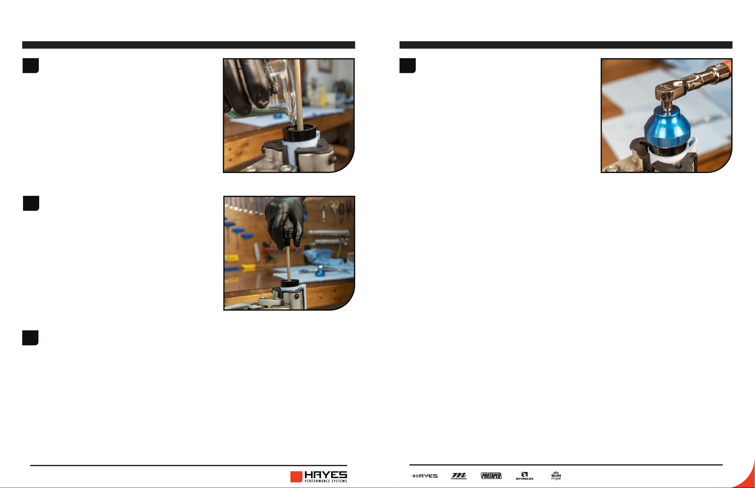
Pour damper oil (5wt fork oil)
into the leg. Fill with 200cc of
damper uid.
Stroke the rebound shaft to
bleed the system and release
the air. You want to stroke the
rebound shaft a few times with
the rebound fully closed, then
turn the rebound knob open two
clicks counterclockwise. Stroke
the rebound shaft another 15-20
times and the system will be bled.

16 17
DORADO EXPERT 37MM SERVICE GUIDE DORADO EXPERT 37MM SERVICE GUIDE
1
2
3
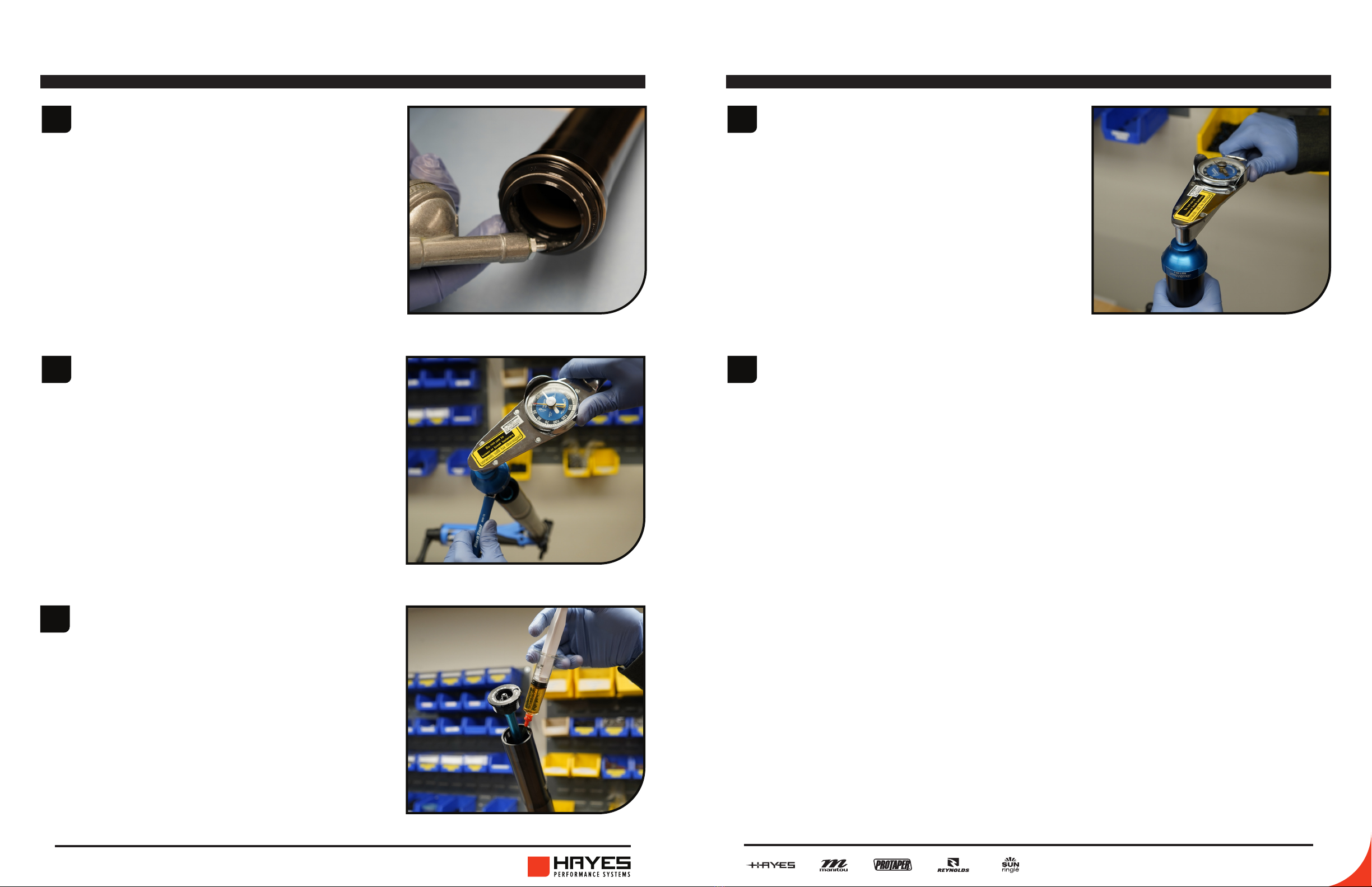
Release the air from the system.
Remove the air cap from the top
of the fork leg, and release the
air pressure using a shock pump.
Ensure all air is released by
gently depressing the air shaft
with a 3mm hex wrench.
If the fork is equippped
with an IRT Ensure all air is
released from that as well!
The air spring leg top cap needs
to be loosened. Loosen the
pinch bolt on the top crown, and
crack the top cap loose with a 16
notch Bottom Bracket Tool.
spring leg disassembly
Loosen the pinch bolts on the
lower crown, and remove the
leg from the fork. Be sure not
to misplace the frame bumper
that will need to come o the
fork leg.
TIP: The ends of the Dorado
sag guide can be used to
spread the clamps apart and
aid in leg removal.
spring leg disassembly
4
5
Lightly clamp the fork leg in a
bike stand. Remove the top cap
from the leg with a 16 notch
Bottom Bracket Tool. Remove the
top cap from the compression rod
with a 13mm wrench on the top
of the compression rod and a 16
notch Bottom Bracket Tool.
Pour the uid out of the leg, and
slide the inner leg out of the
outer leg. Remove the outer
leg from the stand and let it sit
above a drainage pan.
6Wrap the inner in a rag and clamp it lightly in the bike stand with the
compression rod pointing towards the ceiling.

18 19
DORADO EXPERT 37MM SERVICE GUIDE DORADO EXPERT 37MM SERVICE GUIDE
7
8
Loosen the Compression Rod Assembly from the inner leg with a
22mm wrench.
Remove Compression Rod
Assembly from the inner leg.
spring leg disassembly
9
10
Carefully remove the glide ring (129-27922-L013), back up ring (129-
31523-L338) and air piston quad seal (110-215). We recomend using a
plastic pick to ensure the piston is not damage.
Clean air piston then lightly grease the air piston quad seal with Slickoleum
grease and slide it on the air piston. Next install the back up ring and glide
ring on to the air piston.
For information on travel change see page 24 of this guide.
1Inspect the inner leg, inside and out, clean it and be sure it is free from
debris and contaminants. Lube the threads on inside of the inner leg, lube
the outer diameter of the air piston, and ll the piston cup with 3cc of
Slickoleum grease and 1cc Manitou 5w/40 Bath Oil.
2
3
Insert the compression rod, piston rst, into the top of the inner leg using
rotational motion.
Use a 22mm crows foot to
tighten the air spring end cap to
the proper torque of 1.8-2.8 N m
(15-25 in lb).
spring leg assembly
4Replace O-ring #100-027 on the
top cap.
20 21
DORADO EXPERT 37MM SERVICE GUIDE DORADO EXPERT 37MM SERVICE GUIDE
7Inject 35cc of Manitou Semi Bath
oil (5/40wt. Synthetic oil, P/N:
85-0023) into the outer leg on
top of the inner leg.
6Install the top cap onto the end
of the compression rod. Use a 16
notch Bottom Bracket Tool and a
13mm wrench to tighten to the
proper torque of 3.4-4.5 N m
(30-40 in lb).
spring leg assembly
8
9
Fully extend the inner leg and
tighten down the top cap to the
proper torque of 6.8-9.0 N m
(60-80 in lb).
Fill the fork to the desired air pressure.
spring legassembly
5Replace the oil and dust seals
on the outer leg following the
directions on page 22. Inspect
the inside of the outer leg, and
be sure it is free from debris and
contaminants. Coat the inside of
the seal with Slickoleum grease.
Slide the inner leg into the outer
leg, and clamp the top of the
outer leg in the bike stand.

22 23
DORADO EXPERT 37MM SERVICE GUIDE DORADO EXPERT 37MM SERVICE GUIDE
1Using a pick or small blade
screwdriver remove the wear
ring from the outer leg.
2
3
Gently pry out the old dust seal
from the outer leg. A tool we
have found that works well is a
downhill tire lever. If using a at
blade screwdriver to remove
the seal be careful the tip of the
blade does not catch on the lip
inside the outer leg.
Remove the foam ring. Clean seal bore and bushing thouroughly.
dust & oil seal replacement
4Soak new foam in Manitou bath oil. Place foam ring in the bottom of the
seal bore.
dust & oil seal replacement
5
6
Place the new dust seal into the
leg and use the 37mm end of the
seal press to press it completely
into the leg.
Install the wear ring back onto the outer leg.

24 25
DORADO EXPERT 37MM SERVICE GUIDE DORADO EXPERT 37MM SERVICE GUIDE
The Dorado is capable of being internally adjusted from 203mm of travel to 190
or 180mm of travel. This may be done with no change to the spring rate for a
given spring air pressure.
travel change
Wiith the comp-rod assembly
removed locate the top-out nut
(16mm) and screw (20mm) on the
comp-rod. Loosen and unthread the
nut from the screw, then slide apart
to reveal the retaining ring. Lightly
splay the retaining ring to remove
from groove and move to groove
corresponding to the desired travel
position; 203mm is the position
closest to the air piston, 180mm is
the position closest to the end cap.
Rethread the top-out screw and bolt
over the retaining ring, torque to 3,4
N-M [30 IN-LB].
NOTE: Consult pages 16-21 for
air leg assembly and reassembly.
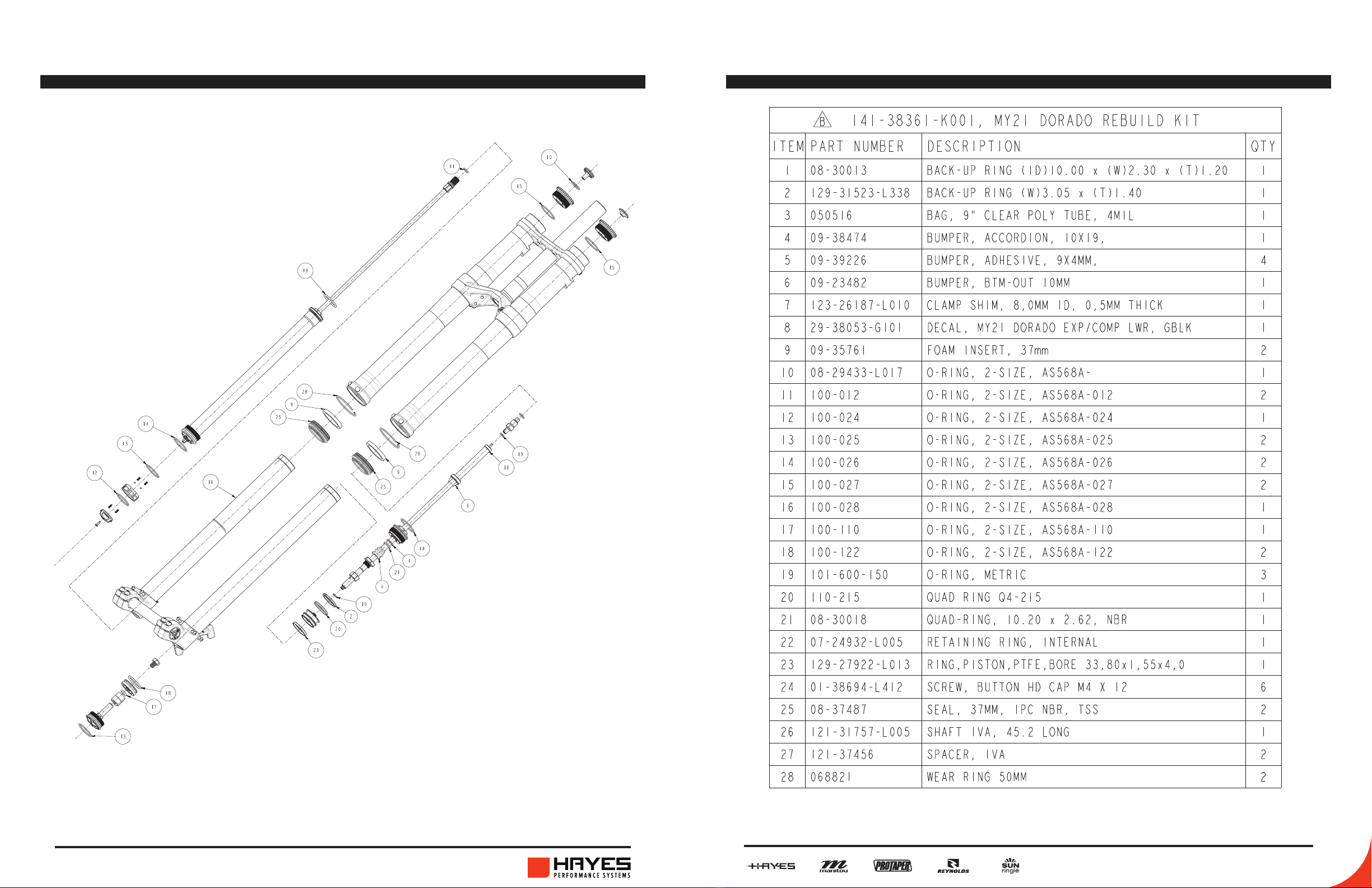
dorado expert exploded view
26 27
DORADO EXPERT 37MM SERVICE GUIDE DORADO EXPERT 37MM SERVICE GUIDE
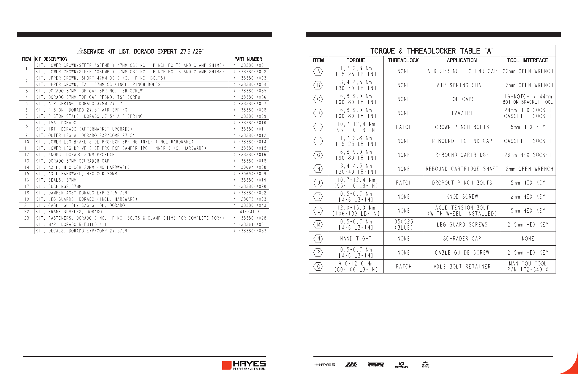
ServiceKit LISt(refernceexplodedview) TORquetable(referenceexplodedview)
28 29
DORADO EXPERT 37MM SERVICE GUIDE DORADO EXPERT 37MM SERVICE GUIDE
O-ring Diagram O-ring chart (Use Diagram for reference)
16F, No. 37, Sec. 3
Mincyuan E. Rd.
Zhongshan District
5800 W. Donges Bay Rd.
Mequon, WI 53092
Dirnismaning 20 a
85748 Garching (b. Munich)
Germany
16F, No. 37, Sec. 3
Mincyuan E. Rd.
Zhongshan District
GLOBAL HEADQUARTERS &
HAYES BICYCLE GROUP USA
HAYES BICYCLE GROUP EU
HAYES BICYCLE GROUP ASIA
facebook.com/ManitouMTB
instagram.com/ManitouMTB
#ScienceofSmooth
Table of contents
Other Manitou Bicycle Accessories manuals

Manitou
Manitou Mara Pro User manual

Manitou
Manitou MATTTOC PRO User manual

Manitou
Manitou BLACK COMP 80/100 User manual

Manitou
Manitou R7 EXPERT User manual

Manitou
Manitou LUXE COMP User manual

Manitou
Manitou MARA PIGGYBACK User manual

Manitou
Manitou Jack SL Dropper Seat Post User manual

Manitou
Manitou SIX User manual

Manitou
Manitou XVERT R User manual

Manitou
Manitou Circus Expert User manual


