atersa A-75M User manual

Professional Photovoltaic Module
EN
DISTRIBUTOR
Intl. Phone numbers
Tel. +34 961 038 430
Fax.+34 961 038 432
E-Mail: atersa@elecnor.com
ATERSA MADRID
C/ Princesa, 25, 2º-2
el: 915 178 452
Fax: 914 747 467
28008 Madrid - Spain
T
ATERSA VALENCIA
P.Industria Juan Carlos I
46440 Almussafes
Valencia - Spain
Tel: 902 545 111
Fax: 902 503 355
Avda. de la Foia, 14
MODULE
Installation and User Manual
(www.atersa.com)
Last revision 17/01/2017
Printed on recycled paper
UNE-EN ISO 14001
UNE-EN ISO 9001
ER-0979/1997 GA-2009/0396
OHSAS 18001
SST-0134/2012
Dispose of the device at an environmental disposal point when it reaches the end of its useful life
EN-MU-41 (4)-E

First, ATERSA and his team thank are grateful for your confidence by purchasing
our products for your photovoltaic installation. This manual contains important
information about handling, installation and maintenance. Please carefully read and
understand this manual before any handling. ATERSA not liable for damages caused
due to improper handling, installation or maintenance.
1.-GENERAL SAFETY 1
2.- TRANSPORT AND HANDLING 1
3.- WARNINGS 2
4.- POSITIONING AND INCLINATION 2
5.- INSTALLATION 3
7
8
6.- MAINTENANCE 8
7.- TECHNICAL SPECIFICATIONS 8
8.- GUARANTEE AND CERTIFICATES 8
5.2.2.- Ground Connection
5.3.- Installation and Guiding of Electrical Cables
INDEX
3
3
4
5
5
5
5.1.- Mechanical Installation
5.2.- Electrical Installation
5.1.1.- Directly on the Structure
5.1.2.- Hook Fixing System
5.1.3.-Guide Insertion
5.2.1.- Electrical Connection of the Juntion Box
MODULE
Installation and User Manual
EN-MU-41 (4)-E

1.-GENERAL SAFETY
2.- TRANSPORT AND HANDLING
.
If not otherwise specified, it is recommended that requirements of the latest national or international
electrical standards be used.
isable to cover the
modules with an opaque material. Do not touch the terminals with both hands and always use
insulated tools on the electrical connections.
Only allow access to the facility by qualified personnel.
Reversing the polarity of the cables destroys the bypass diodes of the junction box.
In normal conditions, the module can produce more current or voltage than the indicated for standard
measurement conditions. So that, when dimensioning the system (cables section, fuses,…) the Isc
and Voc values should be multiplied by 1,25.
Keep children and animals away from PV modules.
Install the modules in a strong structure and that this maintains the fire safety class.
Avoid uneven shade on the PV module surface. Shaded cells may become hot (“hot spot”
phenomenon) which may result in permanent damage to the module.
Follow all safety precautions of other system components used.
Use module for its intended function only.
Store modules in a dry and ventilated room.
Do NOT place modules on an uneven surface
Do NOT place excessive loads on the module or twist the module frame, it may cause severe micro-
cracks at the cell level
Do NOT stand, step, walk and/or jump on the module.
Do NOT drop module or allow objects to fall on module.
Do NOT mark the modules with sharp instrument. Avoid the contact of module back sheet with sharp
objects, as scratches may directly affect product safety
Do not use the junction box to hold or transport the module.
Broken or damaged modules must be handled carefully and with appropriate protective
equipment.(Broken glass can be sharp and can cause injury if it is not handled int he right way .
When carrying a bigger module, two or more people should carry it by its frame and wear non-slip
gloves (to avoid injury by a slipping module, cuts by the edge of a frame etc.
Module placement unsafely before installation can cause breakage, excessive deformation ... that
affect the reliability of the module.
Modules must NOT be manipulated from the central part of the long sides of the frame.´
x
x
x
x
x
x
x
x
x
x
x
x
x
x
x
x
x
x
x
x
x
The modules must be handled carefully during transport, storage and unpacking.
The safety instructions contained in this manual must be strictly followed in order to
guarantee the safety of the user and the integrity of the module.
x
x
Ensure that the installation instructions provided in this document are followed. Guarantees or claims
will not be valid if the described process has not been followed
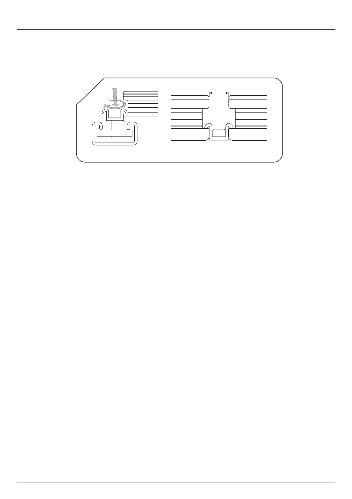
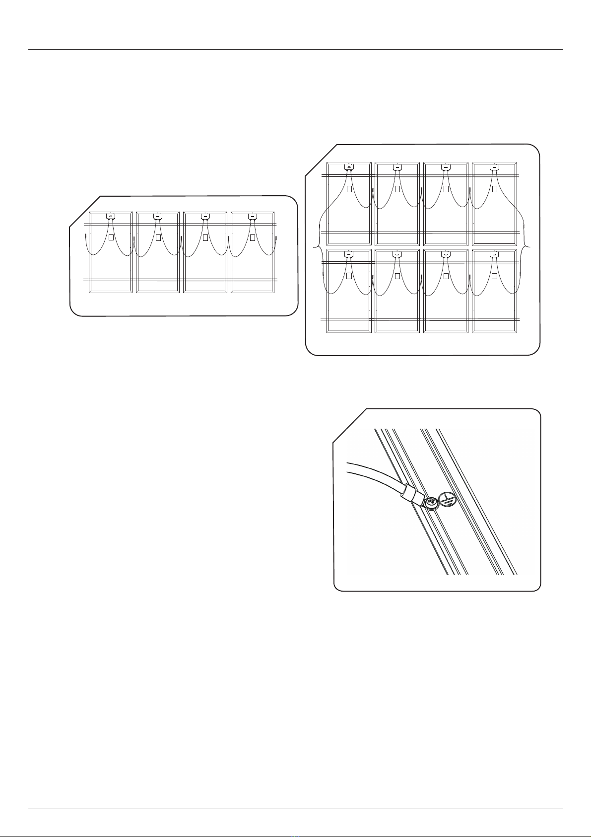
The cable pathway must provide mechanical support for the conductors and must provide sufficient
protection, in accordance with the Low Voltage Electrotechnical Regulations (REBT).
It must be handled by qualified personnel only. When exposed to the light, the modules generate
electricity. If several modules are connected in series, dangerously high voltages may be generated.
To reduce potential electrical hazards during the installation process, it is adv
1
MODULE
Installation and User Manual
EN-MU-41 (4)-E

2
3.-
4.-POSITIONING AND INCLINATION
x
x
x
x
x
x
x
x
x
x
x
x
NO debe intentar reparase ni emplearse ningún modulo roto, ya que el contacto con alguna parte de
este puede provocar en una electrocución.
NO exponer directamente la parte trasera a la luz solar.
Work ONLY under dry conditions, with dry modules and Insulated tools.
Do NOT install the module where flammable gases or vapors are present.
Do NOT drill holes in the frame or glass of the module.
Do NOT treat back sheet and front surface of the module with paint and adhesives.
Do NOT artificially concentrate light on the module.
Do NOT wear metallic jewelry while installing or trouble shooting the module.
Do NOTdisassemble, modify or adapt the module or remove any part of the module.
Be sure to completely ground all modules.
Do not touch terminals while module is exposed to light or during installation.
The connectors must be protected from dust, sund, wather,..., If the connectors are to remain
disconnected in the field.
The modules may be installed on plots of land, terraces, roofs and patios. ATERSA
provides a series of accessories for installations on façades, windows, balconies, walls
and cornices.
In order to ensure optimum performance the modules must not be placed in the shadow
of other objects (plants, snow, buildings, construction elements, other modules, etc.),
at least during the main hours of daylight.
The panels must face south if installed in the northern hemisphere.Guidelines for
achieving maximum annual power output from a fixed installation are provided below. A
design period will be established in order to calculate the size of generator in accordance
with the consumption requirements and radiation. To determine the optimum
inclination we will use the following table (1):
Do not install the solar module in a location where it could be immersed in water or
continually exposed to water, e.g. from a sprinkler.
WARNINGS
Failure to follow these instructions could result in the destruction of the equipment or
personal injury.
HORIZONTAL
INCLINATION
SOLAR LIGHT
SOUTH
(North hemisphere)
INCLINATION
WINTER
DESIGN PERIOD
SUMMER
ANNUAL
Latitude +10º
Latitude -20º
Latitude -10º
1
MODULE
Installation and User Manual
EN-MU-41 (4)-E

The installation in a saline environment must be done with isolators to prevent galvanic
corrosion between the module and the support structure.
When solar modules are connected in series,
they must all face the same direction and have
the same angle of inclination. There must also
be a proper gap (minimum 30cm) between
the module and the surface for ventilation
purposes.
(2)
The ATERSA modules design allows the correct
evacuation of water. They have open edges in
the inside tube.
The modules must be installed on independent fixed structures. The structure must not
transmit stress to the modules.
The longest side of the aluminium frame has a series of 6,7mm diameter drill holes.
Use M6 stainless steel screws to install it on the structure and the proper torque
values should be between 6 to 8Nm. The following screw system should be
employe .
.
5.- INSTALLATION
5.1.- Mechanical Installation
5.1.1.-Directly on the Structure
d (3)
IMPORTANT: NOTDo install the modules
with the junction box in the lower side. View
image
RECOMMENDED
2
NO
* Nota: Use M6 DIN 9021 washer for Hook V4 profile.
Use M6 DIN 125 washer for Hook V1 profile.
M6 WASHER
M6 GROWER WASHER
M6 SCREW
3
FRAME
M6 NUT
STRUCTURE
*M6 WASHER
3
‘
MODULE
Installation and User Manual
EN-MU-41 (4)-E

The placement of the screws, will be always at the distance B (except for ½ 6” 4x9
format modules, where the distance must be C), as shown in the image of the anex
(11-12). Minimum 4 screws per module must be situated.
(5).
5 .1.2.-
:
*Note
*Note
: In corrosive environments (salt spray), place nylon washers to insulate the
panel from the metal parts of the structure.
The aluminium frames of ATERSA’s photovoltaic modules have side channels that make
it easier to fix the module onto the profiles of the installation.
The Hook Fixing System is used to install the modules.This system can be installed on
standard structures , “U” type guide rail or guide insertion.
Fixing on standard structures is carried out using the dead-end clamp, the M8x20
serrated head Allen screw, flat washer and M8 nut. View image (4).
For this type of installation you need a 41x41mm or 41x21mm "U" type perforated
profile. These elements do not come with the Hook Fixing System.
The assembled fixing should look like the picture shown in next figure:
: In corrosive environments (salt spray), place nylon washers to insulate the
panel from the metal parts of the structure.
Installation on standard structures
Installation on “U” type guide rail:
Hook Fixing System
M8 WHASER
M8 NUT
M8x20 ALLEN SCREW
DEAD-END CLAMP
4
M8x20 ALLEN SCREW
DEAD-END CLAMP
M8 GUIDE NUT
5
4
MODULE
Installation and User Manual
EN-MU-41 (4)-E

Installation
5.1.3.- Guide Instertion
5.2.1.-
The proper torque values should be between 16 to 19Nm.
The placement of the dead end clamp (Hook clamp or another type), will be always at
the distance B (except for ½ 6”4x9 format modules, where the distance must be C),as
shown in the image of the annex (11-12). Minimum 4 dead end clamps per module
must be situated.
Assembly drawings depending on the applied load are displayed in annex.(View images
13-14)
Appropriate cable sections must be used to prevent voltage drops, which could cause a
drop in the power of the installation. As a rule, voltage drops in excess of 1,5% must
not be allowed.
(*)Check table of intensities max. of manufacturer's cable and the applicable
regulations.
5.2.- Electrical Installation
CABLE SECTION (Copper section):
Put the first two fixing sets in place, and ensure they are vertically aligned. Fully
tighten the Allen screw (6).
Attach the other two fixing sets, aligning them vertically and move them along the rail
until they reach the panel.
Check that the modules are horizontally and vertically aligned and fully tighten the
screws to ensure the modules are firmly fixed to the guide rail.
The final fixing sets should be attached in the same way as the first two but in reverse.
Take a module that is already in place and then attach the set of fixings.
The modules are ready for installation by inserting into a guide system.
After insertion into the guide rails, panels must be fixed to prevent free sliding on the
guides.
Electrical Connection of the Juntion Box
6
20 mm
-1.5
+1.5
5
MODULE
Installation and User Manual
EN-MU-41 (4)-E

TOTAL SECTION (External diameter):
ELECTRICAL CONNECTION:
A direct cable connection can be made to the direct connect junction box using (max.
4mm ,AWG12) the cable termination spring clips in the junction box. In the manner
shown below, direct connection of cable sizes AWG14 and AWG12 can be
accommodated. The sealing grommet in the 2 rail assembly can accommodate
insulation diameters up to 8.0mm (0.31 inches). To ensure proper termination, cable
insulation should be stripped as shown in figure(7).
On multi-stranded conductors, it is recommended to use wire pins or at least to twist
the strand bundle to ensure all strands are captured in the spring clip. To open the
spring clip window for the cable, use the appropriate tool (see ATERSA product) or a
little screw, to insert vertically into the window as seen in figure 1.View image (8)
The cable can be inserted through the opened window into the clip (figure 2). Once the
cable is installed, lift the screw and the cable is fixed. Attention to the polarity of the
wires. Make sure that the cable is inside the clip and is fixed correctly, if the cable is not
installed correctly the juntion box will be deteriorated (electric arc).
After termination, tighten the grommet nut to compress the grommet around the
cable. Tightening torque for cable screw nut max. 1.5 Nm (0.34 lbf) depends on the
type of cable isolation. Hold cable screw joint with tool.
Connection boxes with integrated cable glands are used with 4mm² cable (AWG 12).
The tightening torque is 1.3 Nm (0.29 lbf). For this is recommended the use of a
slotted socket wrench with wrench size oh 13mm (0.51 inches). ,
. On models
72 and 60 cells, ATERSA provides wiring junction box installed. In these cases,
provided cables may not be modified, deleted, or be replaced by other.
rated 600/1000 V..
2
+0.2
The cable must fulfill the requirements to be used in photovoltaic systems
The cable used
by ATERSA in its modules is for outdoors use, UV resistent, double isolation layer, 1kV,
working temperature range -40ºC to 110ºC,
7
X= 11mm, 0.43 inches
8
Figure 1 Figure 2
6
Modules of 36 cells and ½ 36 cells
MODULE
Installation and User Manual
EN-MU-41 (4)-E

For the junction box to maintain its Class II safety standard, the cables must also be
Class II.
The ground wire must be .To ground the modules, you must use a stainless steel
lug terminal and a self-tapping screw between 4,2x4,5mm and 4,2x16mm. Esto
irá unido a un terminal de ojete semiaislado de 4mm .Ver imagen (10).
Make sure the lug terminal is placed between the wire and module frame. The wire
must fully clamped with the lug terminal and must make good contact with the frame.
There are two drill holes in the solar modules for this purpose, which are marked with a
ground connection (Earthing hole 4mm). View image of annex (11-12). The proper
torque values should be between 1,5 to 2Nm.
The photovoltaic system will be earthed according to the local and national regulations.
2
It is not recommended to connect modules in series with a total Voc higher than the
system Vmax .(View electrical characteristics). View image (9).
4mm
4mm
2
2
10
7
Series installation
Parallel installation
9.1
9.2
5.2.2.- Ground connection
Connect the modules and the support
structure to ground, which will ensure that
any current leakage to any of the
components of the installation will not
reach the installer or user under any
circumstances.
The module frame material is aluminium.
Ground wires must be connected to the
module’s frame at the ground location.
View imagen (10).
MODULE
Installation and User Manual
EN-MU-41 (4)-E

5.2.- Installation and guiding of the electrical cables
All the cables used in the installation must be secured in order to prevent movements
that could cause damage or breakages.
ATERSA solar modules hardly require any maintenance but you must follow a set of
guidelines to ensure good condition.
Our solar modules are made from high-efficiency square cells that are capable of
producing power with low solar radiation. All the models from 75W to 320W have by-
pass diodes in the junction box.
The technical characteristics of the modules are shown in the attached table and
grapichs. View table on page 9 (Polycrystalline) and page 10 (Monocrystalline).
ATERSA guarantees the power output for up to 25 years and provides a 10-year
warranty covering manufacturing flaws.
The modules comply with IEC 61215:2005 and IEC 61730 standards, in addition to
being manufactured under strict UNE-EN ISO 9001:2008, UNE-EN ISO 14001:2004
quality standards.and OHSAS 18001:2007.
6.- MAINTENANCE
7.-
8.-
x
x
x
x
x
x
x
x
x
x
x
x
Maintenance work should be carried out by qualified personnel, as it could involve working with
dangerously high voltages.
Check that dirt has not accumulated on the glass of the panel.
Should this be the case, clean the glass with a sponge and soapy water
In case if water is not available,Module can be dry cleaned with the help of a soft cloth or with soft
sponge to remove dirt, dust.
DO NOT use brushes or abrasive products as they can damage the glass and reduce the power
module.
DO NOT use any chemical abrasive cleaners, degreasers, or cleaning.
DO NOT use water jet cleaning system.
DO NOT clean the panels at their hottest (midday).
Check the cables and electrical connections.
DO NOT use lubricant oils or sprays to connect the connectors..
Appropriate electrically insulating Personal Protective Equipment (PPE) must be worn during any
cleaning or inspection operations.
Check that the mechanical components are not damaged.
TECHNICAL SPECIFICATIONS
GUARANTEE AND CERTIFICATES
According to the norm IEC 61730-1, the application class for this product (ATERSA
module) is class A, which corresponds to modules working in voltages above 50V or
powers above 240W where the access to a general contact is forecasted. The modules
clasified for security within this category fulfill the requirements for ClassII.
8
MODULE
Installation and User Manual
EN-MU-41 (4)-E

* Tyco Electronics Corporation.
** Solar Cable 4mm2
*** Overcurrent protection (Max.
Recommended).
**** Without any additional protection.
(0/+5 W)
14,90%
8,07 A
8,67 A
44,67 V
35,93 V
(0/+5 W)
1645x990x40
1639x984x32
3 / SCHOTTKY Sl1010
Yes (1100mm, Negro)
15,16%
8,14 A
8,78 A
44,82V
36,23 V
(0/+5 W) (0/+5 W)
36 ½
778x659x35
619
68
389
6,20
No
192
Hook V1
TYCO IP65
2 / SCHOTTKY Sl1010
No
15
43
2
20,25 A
18A / 45V / 175ºCm
14,63%
4,05 A
4,24 A
23,20 V
18,52 V
± 8%
14,39%
7,98 A
8,42 A
22,30 V
17,54 V
± 5%
15,42%
8,10 A
8,47 A
23,20 V
18,52 V
± 5%
16,45%
8,43 A
8,84 A
23,40 V
18,99 V
15,68%
8,29 A
8,88 A
37,80 V
30,76 V
36
1476x659x35
619
200
738
11,90
No
416
Hook V1
TYCO IP65
2 / SCHOTTKY Sl1010
No
41
15
2
20,25 A
18A / 45V / 175ºCm
60
15,96,%
8,35 A
8,95 A
37,98 V
31,20 V
(0/+5 W)
16,27%
8,40 A
9,01 A
38,14 V
31,55 V
938
284,5
822,5
21,50
500,5
Hook V4
24
1000 V
-0,43%/ºC
-0,32%/ºC
0,04%/ºC
1000 V
-0,43%/ºC
-0,32%/ºC
0,04%/ºC
Electrical specifications measured in STC. TONC: 47±2ºC
A-75P A-140P
½ 6”4x9
A-150P
6”4x9 6”6x10
290 W 295 W
75 W 140 W 150 W 160 W 255 W 260 W 265 W
A-160P A-255P
1000 V
-0,43%/ºC
-0,32%/ºC
0,04%/ºC
TYCO IP65
15
2
20,25 A
18A / 45V / 175ºCm
A-260P A-265P A-290P A-295P A-300P
300 W
15,42%
8,21 A
8,89 A
44,97 V
36,52 V
A-305P
305 W
(0/+5 W)
15,67%
8,27 A
8,78 A
45,97 V
36,88 V
A-310P
310 W
(0/+5 W)
15,93%
8,35 A
8,83 A
46,14 V
37,14 V
6”6x12
72
1000 V
-0,43%/ºC
-0,32%/ºC
0,04%/ºC
1965x990x40
938
445,5
982,5
24
No
660,5
Hook V4
TYCO IP65
Yes (1250mm, Negro)
3 / SCHOTTKY Sl1010
18A / 45V / 175ºCm
20,25 A
15
21
2
± 5% (0/+5 W)
9
13,65%
4,22 A
4,42 A
23,40 V
18,99 V
A-80P
± 8%
80 W
A-315P
315 W
(0/+5 W)
16,19%
8,43 A
8,88 A
46,31 V
37,37 V
16,45%
8,51 A
8,93 A
46,49 V
37,61 V
(0/+5 W)
320 W
A-320P
Polycrystalline
MODULE
Installation and User Manual
Dimensions (mm ± 2mm)
PHYSICAL CHARACTERISTICS
Isc ( ) Temperature Coefficient
α
Voc ( ) Temperature Coefficient
β
Open Circuit Voltage ( )
Voc
Short-circuit Current ( )
Isc
Max. Power Voltage ( )
Vmp
Number of cells in series
Max. System Voltage
P ( ) Temperature Coefficient
γ
Protection Diodes ( )
Amperes/Vmax/Tj
Protection Diodes (Nº/Type)
Serial Fuse (A) (***)
Max. Nº Modules in Serie
Max. Nº Modules in Parallel (****)
Max. Reverse Current (during 2h)
Max. Power Current ( )
Imp
Laminate Dim. (mm ± 2mm; Fig. 13)
ELECTRICAL CHARACTERISTICS
Tolerance
A (mm) (Figure 12)
B (mm) (Figure 12)
C (mm) (Figure 12)
D (mm) (Figure 12)
Weight (kg approx)
Frame type
Connection Box (*)
Cables (**)
Format
Power
Module Efficiency
EN-MU-41 (4)-E

10
1645x990x40
1639x984x32
3 / SCHOTTKY
Yes (1100mm, Negro)
36 ½
778x659x35
619
68
389
6,20
No
192
Hook V1
TYCO ip65
2 / SCHOTTKY
No
15
43
2
15,1 A
18A / 45V / 175ºCm
14,63%
4,13 A
4,39 A
22,57 V
18,21 V
± 8%
15,60%
4,28 A
4,55 A
22,84 V
18,63 V
± 8%
15,42%
8,25 A
8,79 A
22,57 V
18,21 V
± 5%
16,45%
8,56 A
9,11 A
22,84 V
18,63 V
± 5%
36
1476x659x35
619
200
738
11,90
No
416
Hook V1
TYCO IP65
2 / SCHOTTKY
No
41
15
2
15,1 A
18A / 45V / 175ºCm
60
16,57%
8,59 A
9,07 A
38,65 V
31,44 V
(0/+5 W)
938
284,5
822,5
21,50
500,5
Hook V4
24
1000 V
-0,43%/ºC
-0,34%/ºC
0,03%/ºC
1000 V
-0,43%/ºC
-0,34%/ºC
0,03%/ºC
A-75M A-80M
½ 6”4x9 6”4x9 6”6x10
75 W 80 W 150 W 160 W 270 W
A-150M A-160M
1000 V
-0,43%/ºC
-0,34%/ºC
0,03%/ºC
TYCO IP65
15
2
15,1 A
18A / 45V / 175ºCm
A-270M A-295M
295 W
(0/+5 W)
15,16%
8,13 A
8,68 A
44,37 V
36,31 V
A-300M
300 W
(0/+5 W)
15,42%
8,22 A
8,76 A
44,63 V
36,51 V
6”6x12
72
1000 V
-0,43%/ºC
-0,34%/ºC
0,03%/ºC
1965x990x40
938
445,5
982,5
24
No
660,5
Hook V4
TYCO Ip65
Yes (1250mm, Negro)
3 / SCHOTTKY
18A / 45V / 175ºCm
15,1 A
15
21
2
A-305M
305 W
(0/+5 W)
15,68%
8,31 A
8,84 A
44,89 V
36,71 V
(0/+5 W)
15,66%
8,34 A
8,89 A
37,76 V
30,57 V
(0/+5 W)
15,97%
8,44 A
8,99 A
37,90 V
30,79 V
(0/+5 W)
15,35%
8,24 A
8,79 A
37,62 V
30,35 V
255 W 260 W
250 W
A-250M A-255M A-260M
16,27%
8,54 A
9,04 A
38,40 V
31,03 V
(0/+5 W)
265 W
A-265M A-310M
(0/+5 W)
15,94%
45,15 V
36,91 V
8,40 A
8,92 A
310 W
(0/+5 W)
A-320M
320 W
16,52%
8,52 A
8,99 A
46,08 V
37,56 V
16,19%
8,45 A
8,94 A
45,72 V
37,30 V
(0/+5 W)
315 W
A-315M
MODULE
Installation and User Manual
Monocrystalline
Dimensions (mm ± 2mm)
PHYSICAL CHARACTERISTICS
Isc ( ) Temperature Coefficient
α
Voc ( ) Temperature Coefficient
β
Open Circuit Voltage ( )
Voc
Short-circuit Current ( )
Isc
Max. Power Voltage ( )
Vmp
Number of cells in series
Max. System Voltage
P ( ) Temperature Coefficient
γ
Protection Diodes ( )
Amperes/Vmax/Tj
Protection Diodes (Nº/Type)
Serial Fuse (A) (***)
Max. Nº Modules in Serie
Max. Nº Modules in Parallel (****)
Max. Reverse Current (during 2h)
Max. Power Current ( )
Imp
Laminate Dim. (mm ± 2mm; Fig. 13)
ELECTRICAL CHARACTERISTICS
Tolerance
A (mm) (Figure 12)
B (mm) (Figure 12)
C (mm) (Figure 12)
D (mm) (Figure 12)
Weight (kg approx)
Frame type
Connection Box (*)
Cables (**)
Format
Power
Module Efficiency
* Optionally ATERSA have available junction boxes with
QUAD (Ip54) version on request.
** Solar Cable 4mm2
*** Overcurrent protection (Max.
Recommended).
**** Without any additional protection.
Electrical specifications measured in STC. TONC: 47±2ºC
EN-MU-41 (4)-E

Professional Photovoltaic Module
EN
ANNEX
Installation and User Manual
Printed on recycled paper
UNE-EN ISO 14001
UNE-EN ISO 9001
ER-0979/1997 GA-2009/0396
OHSAS 18001
SST-0134/2012
Dispose of the device at an environmental disposal point when it reaches the end of its useful life
ANNEX
EN-MU-41 (4)-E

Dimensions in mm
6,7
A
D
C
B
HOOK V1
29
35
HOOK V4
38
40
B
5
15
A
984
32
* The areas marked in the drawing (A and B) are intended for the
fixation of the laminate and ensure proper installation.
Always use fastening systems that do not damage the
laminate/module
A 80 mm.
11 mm. B 13 mm.
9 mm. B 10 mm. (6”4x9 / 6”4x9)½
225±25.0 595±25.0 595±25.0 225±25.0
1639
11 General dimensions Polycrystalline modules
Dimensions in mm
Module Laminate
*
ANNEX
EN-MU-41 (4)-E

12
6,7
A
D
C
B
HOOK V1
29
35
HOOK V4
38
40
225±25.0 595±25.0 595±25.0 225±25.0
B
1639
5
15
*
A
984
32
A 80 mm.
11 mm. B 13 mm.
9 mm. B 10 mm. (6”4x9 / 6”4x9)½
General dimensions Monocrystalline modules
Module Laminate
ANNEX
Dimensions in mm
* The areas marked in the drawing (A and B) are intended for the
fixation of the laminate and ensure proper installation.
Always use fastening systems that do not damage the
laminate/module
Dimensions in mm
EN-MU-41 (4)-E

Clamping method Hook M8 (*)
Short side
14
Module assembly drawings depending on the applied mechanical load
Clamping method Other(*)
Long side
2400Pa
0000000000000
Clamping method Other(*)
Short side
0000000000000
0000000000000
Clamping method Hook M8 (*)
Long side
0000000000000
0000000000000
Guide instertion
(*) The areas marked in the drawing (A and B) are intended for the fixation of the laminate and ensure
proper installation.
Always use fastening systems that do not damage the laminate.
According to standard IEC 61215:2005
Note: ATERSA reserves the right to modify the product specifications without notice.
For more extensive information about the terms of the warranty and certificates y, please see our website: www.atersa.com
13
13.2
Polycrystalline and Monocrystalline
13.1
Laminate assembly drawings depending on the applied mechanical load
14.1
E
0000000000000
F 80 mm.
11 mm. G 13 mm.
E 225 ± 25.0 mm=
Laminates 60 cells
Using two sidebars at distance E from
the edge and a central.
E
G
F
E
Special clamps for laminates (*)
Long side
F
2400Pa
BB
0000000000000
A
BB
0000000000000
Directly on the Structure
BB
BB
Distance A: Distance B:60mm (Minimum)/ module 72 cells B 445.5 mm; modulel 60 cells B 284.5 mm= =
5400Pa
Clamping method Hook M8 (*)
Long side
Clamping method Other(*)
Long side Screws
A
EE
ANNEX
EN-MU-41 (4)-E
Module with 72 cells and 4.0 mm. of thickness of the glass.
With 3.2 mm. 2.400 Pa.
This manual suits for next models
29
Table of contents
Other atersa Solar Panel manuals
Popular Solar Panel manuals by other brands

Grape Solar
Grape Solar GS-300-KIT Quick connect guide

Thermo King
Thermo King ThermoLite installation guide

LDK Solar
LDK Solar LDK-160D-24s installation guide

BougeRV
BougeRV ISE179 user manual

Maxeon
Maxeon SunPower SPR-MAX5-415-E3-AC Safety and installation instructions

Bosch
Bosch TSS Series Installation and maintenance instructions

Silicon Solar
Silicon Solar MarineSol ThinFilm 12V30W user manual

Brunton
Brunton Solaris 26 instruction manual

FREEFORCE
FREEFORCE ULTRALITE 600 user manual

Dometic
Dometic NDS BS 115WP Short Operating Manual

Flexopower
Flexopower SK79 instructions

Wolf
Wolf CFK-1 Installation, operating and maintenance instructions