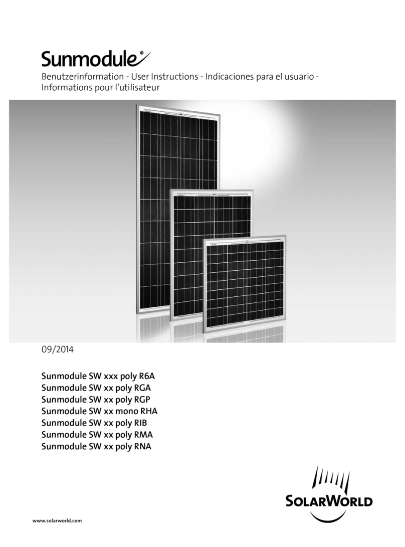
SolarWorld SW poly/RGA Series Operation manual

1
User Information
SolarWorld O Grid Solar modules
Stand: 01.03.2010
Carefully read through these instructions before installing,
operating, or servicing the PV system. Failure to follow these
instructions may result in bodily injury or damage to property.
Keep these instructions!
Classification of safety guidelines
Warning symbol, signal word Warning levels
DANGER! Warns of imminent danger of death.
WARNING! Warns of possible danger of death
and/or serious injury.
CAUTION! Warns of possible personal injury.
ATTENTION Warns of damage to property without
the possibility of personal injury.
Important information.
▹ Working on a PV system requires specialized knowledge
and must therefore be carried out only by appropriately
qualified and authorized personnel. Keep children away.
▹ If the products are used in the USA please pay attention to
the information marked [USA].
▹ This User Information gives you information on installati-
on and safety when handling photovoltaic modules from
SolarWorld AG (in the following referred to as “modules”).
Safety information
DANGER!
Danger of death from electric shock
▹ Modules generate electricity as soon as they are exposed
to light. Connections variations can cause high voltages
and/or high currents. Do not fit modules and wiring with
wet plugs and sockets.
▹ Exercise extreme caution when carrying out work on
wiring.
▹ The inverter can produce dangerous, high voltages, even
when not connected.
▹ Exercise extreme caution when working on the inverter
and wiring.
DANGER!
Danger of death from arcing
▹ Modules generate direct current (DC) when any amount
of sunlight shines on them. When breaking a connected
string of modules (e.g. when disconnecting the DC line
from the inverter under load), a lethally strong arc can
occur.
▹ Never remove the module from the inverter while it is
still connected to the main grid.
▹ Ensure that the cable connections are in perfect condi-
tion (no cracking, no soiling, or other contamination).
WARNING!
Danger of falling
▹ There is a danger of falling while working on the roof
as well as when climbing up to or down from the roof.
It is very important that you pay attention to accident
prevention regulations and use adequate fall prevention
devices.
WARNING!
Falling objects
▹ When assembling on roofs there is the risk of tools,
assembling materials or a module falling o the roof and
injuring persons below.
▹ Create a hazard zone on the ground level before
beginning with the assembly and warn persons in the
surrounding area.
WARNING!
Flammable materials
▹ Modules may not be operated in the proximity of devices
or rooms from which flammable gasses or dust may
escape or collect.
▹ Roof construction and assembly may have eects on fire
protection.
CAUTION!
Risk of hand injuries
▹ Risk of squeezing hands when mounting support frame
and module.
▹ Work may be carried out by trained personnel only.
▹ Wear protective gloves.
You can receive further information about
▹ dimensioning and setting up photovoltaic systems
▹ wiring
▹ connection technology
▹ elevation
from your photovoltaic dealer.
Intended use
Modules use the photovoltaic eect to transform light into
electricity. The modules are used outdoors and, depending
on type, mounted on support frames, stands, or flat surfaces.
Multiple modules can be connected serially or parallel. The
number of connectable modules is limited, see chart “Types
of modules”. Connect only modules of the same type within
one system. Modules must not be directly connected to an
electrical consumer. Do not take the modules apart and do
not remove the type plate. Do not drill into the frame or into
the glass of the module, this will void your warranty.
Intended use also includes following the installation guide-
lines, as well as following the mentioned maintenance and
cleaning instruc-tions. The manufacturer will not be held lia-
ble for damages caused by failure to observe the installation
guidelines.

2
A fitting of the module as overhead glazing or vertical
glazing (facade) is prohibited in several countries. It is
absolutely essential that you adhere to the current legal
requirements – such as building permission – of local,
regional, and national authorities.
To ensure proper operation of the system and prevent
damage please make sure that:
▹ the module is not shadowed by trees, antennas etc.,
▹ the module is suciently ventilated from the back side,
▹ the back sides of the modules are not treated with paint or
adhesives.
▹ sunlight is not concentrated on the modules via mirrors or
lenses.
Types of modules
SW xx poly/
RGA
SW xx poly/
RHA
SW xx poly/
RIA
SW xx poly/
R6A
SW xx mono/
R5A
Performance
[W]
30-45 50-70 70-90 100-140 70-90
Dimensions
lxwxh [mm]
572 x 680
x 34
806 x 680
x 34
1058 x 680
x 34
1508 x 680 x 34 1229 x 556 x 34
Pmax [W] 30 – 35 – 40
– 45
50 – 60 – 70 70 – 75 – 80 –
85 – 90
100 – 110 – 120
– 130 – 140
70 – 75 – 80 –
85 – 90
Weight [kg] 4,6 6,7 8,1 11,8 8,2
max. system
voltage
IEC 1000 VDC
NEC 600 VDC
IEC 1000 VDC
NEC 600 VDC
IEC 1000 VDC
NEC 600 VDC
IEC 1000 VDC
NEC 600 VDC
IEC 1000 VDC
NEC 600 VDC
max. number
of modules
connected
parallel
5 3 3 2 3
Image
Diodes 2 x F1200D 2 x F1200D 2 x F1200D 2 x F1200D 2 x F1200D
Unpacking, interim storing and handling
During assembly and electrical installation cover the modu-
les with opaque material to prevent electricity from being
generated.
Do not assemble on roofs and buildings during high winds.
Wind also increases the risk of injury when lifting or moving
support frames with several mounted modules.
▹ Leave modules in packaging until ready to install.
▹ Do not hold or transport the module by the junction box.
▹ Do not step or stand on the module.
▹ Do not drop the module and do not let anything fall onto
the module.
▹ Do not place heavy objects on the module.
▹ Do not set the module roughly onto the floor, particularly
not onto the corners.
Do not use any module with broken glass.
Assembly
▹ Recommended angle of inclination for photovoltaic opera-
ted stand-alone systems/year-round use.
Latitude Fixed angle of inclination
0° - 15° 15°
15° - 25° equal to the latitude
25° - 30° Latitude + 5°
30° - 35° Latitude + 10°
35° - 40° Latitude + 15°
over 40° Latitude + 20°
Your local photovoltaic dealer can give you information
about a suitable installation location.
Modules must be attached to support frames or with assem-
bly sets to a solid base. The whole photovoltaic system must
withstand the mechanical loads typical for the specific region.
When selecting support frames ensure that they withstand
strong winds and snow loads and comply with local ordinan-
ces and regu-lations. Ensure that the modules are not exposed
to undue forces caused by thermal expansion of the support
frame. The support frames should be made of resistant,
corrosion-proof, and UV resistant material.
Ground mounting: Choose the height of the frame so that
the module can not be covered by snow or plants for a longer
period of time.
Roof mounting: When mounting on roofs and buildings
ensure that the roof construction is adequate. In some cases a
special support frame may be required.
Mast mounting: When installing a module on a masthead
it must be ensured that the mast has sucient stability to
resist expected wind speeds and wind gusts without notably
bending. The mast must have an adequate foundation. Use an
assembly frame to attach the module to the mast.
Mounting
Screw the modules onto the four attachments designated for
this purpose. Consult your dealer if you plan to assemble the
modules in other places than those designated.
The modules can be mounted to the substructure by clamping
on (example A) at the front side or by screwing (example B) at
the back side. The clamping area (example A) of the washer
must cover at least 135 mm² per fixation point.
A torque wrench must be used for assembly.
1
2
33
1
Example A: clamping on Example B: Screwing
1 V2A-Serrated ange nut
2 V2A-Clamping washer
3 V2A-T-head bolt
Image 1: Mounting

3
Cable protection
We recommend securing the cables to the mounting system
using UV resistant cable ties. Protect exposed cables from
damage (for example by laying them in plastic pipes). Avoid
direct exposure to sunlight. A bending radius of minimum 35
mm must be maintained.
SolarWorld AG recommends laying all electrical cables and
connections in compliance with national regulations for
electrical instal-lations. Bypass diodes are factory installed.
Opening the junction box
DANGER!
Danger of death from electric shock
▹ In order to ensure protection against electrical shock the
junction box MUST be disconnected from all external
power sources while installing the cables! DO NOT
CONNECT UNDER LOAD‼!
To open, use a screwdriver with
a 3 – 5 mm wide flat head. Insert
the screwdriver into the marked
opening. Move flap until hook
re-leases the lid. Do not pull the
lid out at once.
Image 2: Open junction box
Wiring
▹ Strip 11 mm of insulation from cable.
▹ Open cable gland nut.
▹ Use a small flathead screwdriver to press and hold down
terminal clamp.
▹ Push cable through cable gland and lead it to terminal
clamp. Pay attention to polarity.
▹ Removal of tool causes a frictional connection.
▹ Tighten cable gland nut (SW 13) with 1.3 – 1.5 Nm.
Image 3: Side view of junction box (cross section)
After completing the electrical connection…
Hang the lid on the housing and, by locking the lid in place,
secure it to the lower part of the housing. Make sure that the
lid fits level on the lower part of housing and that the seal is
fitted into the area intended. To ensure this the lid must be
pressed down all around.
An expert grounding of the module frame lies in the respon-
sibility of the installing company. If the building already has
a lightning protection system or if one is intended, the PV
system must be integrated into the protection system against
direct lightning strike. Country specific standards must be
adhered to. A UL authorized grounding method is mandatory
in the USA and Canada.
In the examples shown, the tightening torque is at least 5 Nm
(using M6 screws made of V2A). Use the existing holes for
securing the module; do not drill any additional holes (doing
so will void the warranty). Use appropriate corrosion-proof
fastening materials.
Installation
Correct wiring scheme
To decrease voltage caused by indirect lightning strikes, all
connecting cables should be as short as possible. Check that
the wiring is correct before commissioning the system. If the
measured open circuit voltage diers from the specifications,
then there is a wiring fault. Ensure that the polarity is correct.
Comparison: Serial connection and parallel connection
Serial connection is applied in case of high operating voltages
(for battery storage with high operating voltage). The voltages
of the individual modules add up, the electricity stays the
same.
Parallel connection, for use when a great amount of electricity
is needed (for battery storage with high capacity). The electri-
city of the individual modules adds up, the voltage stays the
same. The modules must be protected by suitable blocking
diodes against return currents > 12 A.
Use of appropriate materials
Use only special solar cables (for example PV1-F or [USA]:
PV-Wire) and appropriate connectors. Ensure that they are in
perfect electrical and mechanical condition. Use only single
wire cables made of copper strand with a diameter between
2.5 mm² (AWG 14) and 4 mm² (AWG 12). Select an appropriate
conductor diameter to minimize voltage drop. The outer dia-
meter of the cable must be between 4.5 mm and 6.9 mm
Underwriters Laboratories Information (U.S. and Canada)
▹ The solar module electrical characteristics are within
+/-10% of the module label indicated values of Isc, Voc,
and Pmpp under Standard Test Conditions (irradiance of
100 mW/cm2, AM 1.5 spectrum, and a cell temperature of
25°C/77°F)
▹ Under normal conditions, a photovoltaic module is likely
to experience conditions that produce more current and/
or voltage than reported at standard test conditions.
Accordingly, the values of Isc and Voc marked on this
module should be multiplied by a factor of 1.25 when
determining component voltage ratings, conductor
capacities, fuse sizes, and size of controls connected to the
PV output.
▹ Refer to section 690-8 of the National Electric Code (NEC)
for an additional multiplying factor of 125% (80% de-rating)
which may be applicable
▹ Over-current protection shall be in accordance with the
requirements of Article 240 of the NEC
▹ Conductor recommendations: 14-12 AWG (2.5-4 mm2) USE-2
or PV-wire, 90°C wet rated
▹ Cable conduits should be used in locations where the
wiring is accessible to children or small animals
▹ Modification or tampering of diodes by unqualified
personnel is not permitted. Please consult a SolarWorld
Service Center for additional information regarding diode
replacement/repair.

4
Example UL [USA]:
The modules can be connected to the grounding holes using
a lay-in lug and a bolt with serrated washer, washer, and nut
(see image: “Correct connection of grounding wire“).
1
2
3
4
5
1 Nut
2 Serrated washer
3 Washer
4 Bolt
5 Lay-in lug
Image 4: Ground connection using a cable lug, a bolt, a serrated washer,
washer, and nut.
We recommend using the components listed blow.
Any UL approved PV grounding method and components are
also acceptable in the US and Canada.
Table: Recommended components
Item Description Manufacturer
/ Distributor
Manufacturer
/ Part number
Grounding lug Lay-in lug Ilsco GBL-4
Bolt #6-32, SS McMaster Carr 92314A148
Serrated washer M5, SS McMaster Carr 91120A140
Washer ID 9/64“, OD
3/8“, SS
McMaster Carr 92141A007
Nut #6-32, SS McMaster Carr 91841A007
See www.ilsco.com; www.mcmaster.com
WARNING!
Warns of explosion risk from batteries
▹ If modules are used to load batteries, the battery is to be
installed in such a manner that the performance of the
system and its users are not endangered.
▹ The recommendations and regulations of the battery
manufacturer concerning installation, operation, venti-
lation, and maintenance must be adhered to.
▹ Batteries should be kept away from persons and ani-
mals and protected from sunlight, rain, snow, or falling
objects.
▹ When loading most batteries generate gaseous
hydro-gen which can also explode. To prevent this from
happening sucient ventilation must be provided and
open flames and sparking must be avoided. For outdoor
installations the batteries should be kept in a ventilated
container provided especially for this purpose.
Maintenance
SolarWorld recommends inspecting the system in regu-
lar intervals: All PV modules should be inspected yearly for
safe electrical connections, corrosion and intact mechanical
connections. Loose connec-tions can damage the module or
the module series. During this inspection it should also be
ensured that the wiring is in good condition. Given a sucient
tilt (over 15°) it is usually not necessary to clean the modules
(rainfall will have a self-cleaning eect). Modules that are
installed horizontally (0 – 15° tilt angle) must be cleaned more
often because a sucient self-cleaning from rainfall, as with
stronger tilted modules, is not given.
In case of heavy soiling we recommend cleaning the modules
using lots of water (from a hose) without any cleaning agents
and using a gentle cleaning implement (a sponge). Dried dirt
must never be scraped or rubbed away, as this may cause mic-
ro-scratches. Any problems that may arise should be solved by
an authorized specialist. Please also observe the maintenance
information of all components used, such as support frames,
charging regulators, inverters, batteries etc.
Disclaimer of liability
SolarWorld accepts no liability for the use and functionality
of the modules in case of non compliance with this User
Information. Since compliance with this guide and the
conditions and methods of installation, operation, use and
maintenance of the modules are not checked or monitored
by SolarWorld AG, SolarWorld AG accepts no liability for
damage arising through improper use or incorrect installation,
operation, use or maintenance.
SolarWorld AG
Martin-Luther-King-Str. 24
53175 Bonn
Germany
Telefon: +49 - 228 - 55920 - 0
Telefax: +49 - 228 - 55920 - 99
www.solarworld.de
SolarWorld Ibérica, S.L.
C/La Granja 15, Bloque B-1°B
28108 Alcobendas, Madrid
Spain
Tel.: +34 - 91 - 4905999
Fax: +34 - 91 - 6574967
www.solarworld.es
SolarWorld California Inc.
4650 Adohr Lane
Camarillo, CA 93012
USA
Tel.: +1 - 800 - 947 - 6527
Fax: +1 - 805 - 388 - 6395
www.solarworld-usa.com
SolarWorld France
Hôtel de l’Entreprise,
Bouchayer-Viallet
31, rue Gustave Eiel
38000 Grenoble
France
Tel + 33 (0) 43 821 00 50
Fax +33 (0)4 38 21 00 59
http://www.solarworld.fr
SolarWorld Africa Pty. Ltd.
20th Floor
1 Thibault Square
Cape Town, 8001
South Africa
Tel.: +27 - 21 - 421 - 8001
Fax: +27 - 21 - 421 - 8002
www.solarworld-africa.co.za
SolarWorld Asia Pacific Pte. Ltd.
72 Bendemeer Road
#07-01, Luzerne
Singapore 339941
Singapore
Tel.: +65 - 6842 - 3886
Fax: +65 - 6842 - 3887
www.solarworld.sg
This manual suits for next models
4
Other SolarWorld Solar Panel manuals
SolarWorld
SolarWorld Sunmodule SW xx poly RGA User manual
SolarWorld
SolarWorld Sunmodule Protect Series User manual
SolarWorld
SolarWorld Sunmodule SWA XL mono Series User manual
SolarWorld
SolarWorld Sunmodule Plus User manual
SolarWorld
SolarWorld Sunmodule SW xx poly RHA User manual
SolarWorld
SolarWorld SunCarport User manual

SolarWorld
SolarWorld Suntub User manual
SolarWorld
SolarWorld Kit User guide
SolarWorld
SolarWorld Sunmodule SW *** poly User manual
SolarWorld
SolarWorld solar modules User manual
