Athena UPS APA-103T User manual
USER’S MANUAL
Line interactive UPS
650VA/1KVA/1.5KVA/2KVA/
3KVATR/5KVATR/7.5KVATR PM/10KVATR PM

1
Uninterruptible Power Supply
CONTENTS
1. INTRODUCTION .............................................………………….........
2
2. SAFTY INSTRUCTION...................……...………………………..…....
3
3. SYSTEM DESCRIPTION..........................……..........................….....
6
4. OUTLINE DESCRIPTION..............................……….…………...........
8
5. CABLE CONNECTION……………………………………………………
21
6. OPERATION ................................................……...............................
22
7. TROUBLE SHOOTING GUIDE.......................……….……………...…
27
8. OPERATION MODES OF THE UPS ..............……….……………......
29
9. COMPUTER INTERFACE ...........................……...............................
31
10. SPECIFICATION…………………........……………….…..….…..…....
32

2
1. INTRODUCTION
1.1 General Description
The continuity of electrical power is an essential requirement for critical load
operations .The Uninterruptible Power System (UPS) is designed to meet the
user‘s need of present computer, server and the equipment of office automation
that make the UPS more compact and less noisy.
To choose the UPS as your equipment protector is a wise investment because it
supplies reliable,pureandstablepower at affordableprice.
1.2 Key features
Line-interactive Sine-wave Topology
Intelligent Charger w/PFC
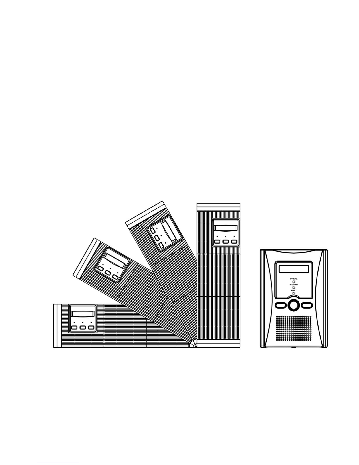
Detachable Dot-Matrix LCD Panel (1K and above)
Compact Size,
Rack/Tower Convertible (1K to 10K)
Intelligent Fan Speed Control
Integrate with Generator Set
Hot Swappable Battery (Rack model )
Multiple Interface Options (1K and above)
Cold Start

3
1.3 Important Notices
To be sure that the UPS will operate correctly, the following items should be
noticed:
1. Read instructions carefully before operating the UPS.
2. UPS power connection instruction should be followed.
3. Please don‘t open the case to prevent danger.
4. If the UPS will be stored for long period, the battery must be charged once
every 60 days.
5. Retain the load within the rating of the UPS to prevent faults.
6. Handle unusual events according to the trouble-shooting guide.
7. Keep the UPS clean and dry.
2. SAFTY INSTRUCTION
2.1 Transporting
1. Disconnect all power cables if necessary.
2. Be careful not to damage the UPS while transporting.
3. Don‘t move or put the UPS upside down.
4. Please transport the UPS system only in the original packaging (to protect
against shock and impact).

4
2.2 Positioning
1. Do not put the UPS on rugged or declined surface.
2. Do not install the UPS system near water or in damp environments.
3. Do not install the UPS system where it would be exposed to direct sunlight or
near heat.
4. Do not block off ventilation openings in the UPS system’s housing and don’t
leave objects on the top of the UPS.
5. Allow a minimum distance of 10 cm in the rear and two sides of the UPS for
ventilation.
6. Keep the UPS far away from heat emitting sources.
7. Do not expose it to corrosive gas.
8. Ambient temperature : 0℃- 40℃
2.3 Installation
1. Connect the UPS system only to an earthed shockproof socket outlet.
2. Do not connect domestic appliances such as hair dryers or office equipment
that would overload the UPS system (e.g. laser printers) to UPS output
sockets.
3. Place cables in such a way that no one can step on or trip over them.

5
2.4 Operation
1. Do not disconnect the mains cable on the UPS system or the building wiring
socket outlet during operations since this would cancel the protective earthing
of the UPS system and of all connected loads.
2. The UPS has its own internal power source (batteries). The output terminals
may be live even when the UPS is not connected to the AC supply.
3. Ensure that no fluids or other foreign objects can enter the UPS system.
2.5 Maintenance and Service
1. Caution - risk of electric shock.
Even after the unit is disconnected from the mains power supply (building
wiring socket outlet), components inside the UPS system are still connected to
the battery and are still electrically live and dangerous. Before carrying out any
kind of servicing and/or maintenance, disconnect the batteries and verify that
no current is present.
2. Only persons adequately familiar with batteries and with the required
precautionary measures may exchange batteries and supervise operations.
Unauthorized persons must be kept well away from the batteries.
3. Batteries may cause electric shock and have a high short-circuit current.
Please take the precautionary measures specified below and any other
measures necessary when working with batteries:
- remove wristwatches, rings and other metal objects
6
- use only tools with insulated grips and handles.
4. When changing batteries, install the same number and same type of batteries.
5. Do not attempt to dispose of batteries by burning them. This could cause
battery explosion.
6. Do not open or destroy batteries. Escaping electrolyte can cause injury to the
skin and eyes.
3. SYSTEM DESCRIPTION
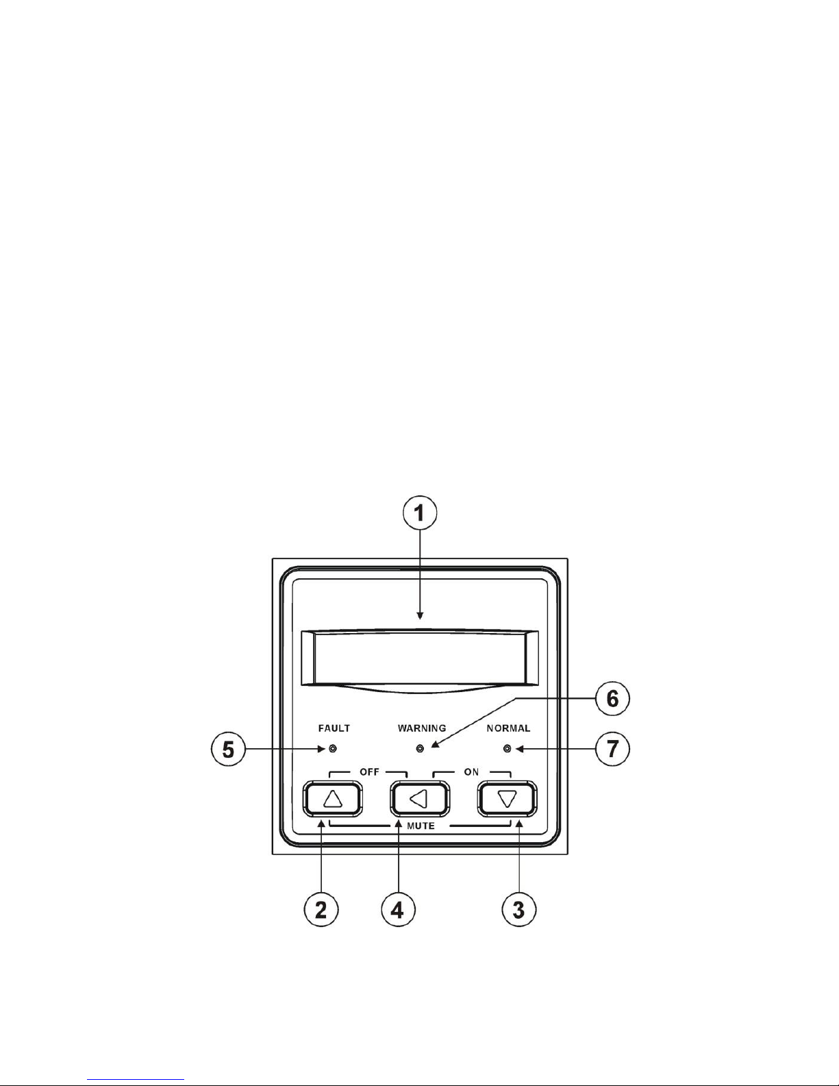
3.1 Front Panel Description for LCD Model
7
Buttons
Description
1. LCD Display
WhenAC plugs in (UPS is not switched on.) this LCD
display light will be on. UPS operation information can be
seen including UPS status, input/output voltage,
input/output frequency, battery voltage, battery capacity,
load capacity, temperature, and event logs. UPS output
voltage and frequency can be set from it here, too.
2. Up Key
Press to select upward.
3. Down Key
Press to select downward.
4. Enter Key
Press to enter the setting page and save the settings.
Switch ON
Press both Key (3) and Key (4)
simultaneously for 3 seconds
until UPS beeps for twice.
Switch Off
Press both Key (2) and Key (4)
Simutaneouly for 3 secnonds
until UPS beeps for twice.
Mute
When UPS is on and is on DC mode, UPS
will beep every 4 seconds. Press both
Key (2) and Key (3) simultaneously for 3
seconds to turn off UPS buzzer.
NOTE:UPS beeper will be enabled automatically in server
cases such as overload, overheat, and battery low...etc.
LED indication:
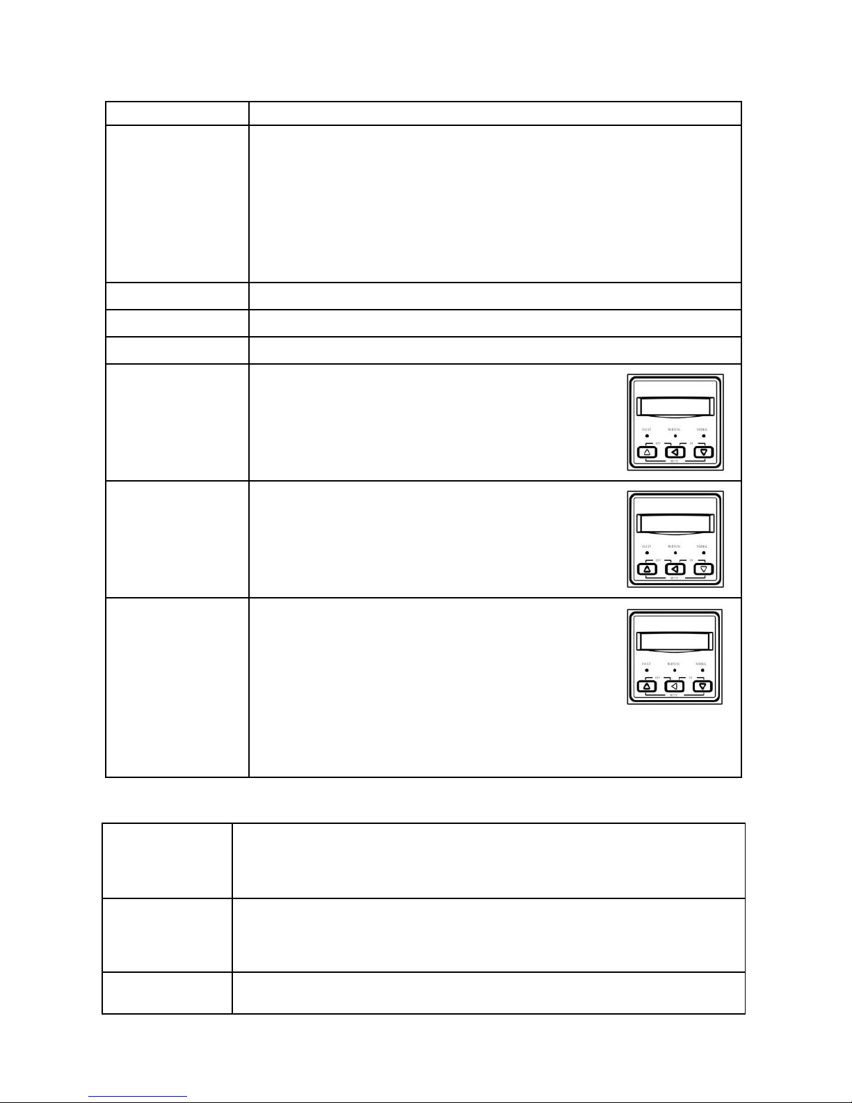
5. Fault
LED
Red LED indicates that the UPS is in a fault condition.
There are problems needed to be solved. Such as
inverter abnormal or over-temperature or DC_BUS fault.
6. Warning
LED
Yellow LED indicates that the UPS is in a status which the
user should be aware but not worried yet. Such as UPS
overload or UPS is on battery back-up.
7. Normal
LED
Green LED indicates that the UPS is operating normally.

8
4. OUTLINE
4.1.Description
650VA Tower Case

9
1KVA/ 1.5K/ 2KVA Tower Case
10
1KVA/ 1.5KVA/ 2VA Rack & Tower Convertible Case
11
3KVA Rack & Tower Convertible Case
12
5KVA Rack & Tower Convertible Case
13
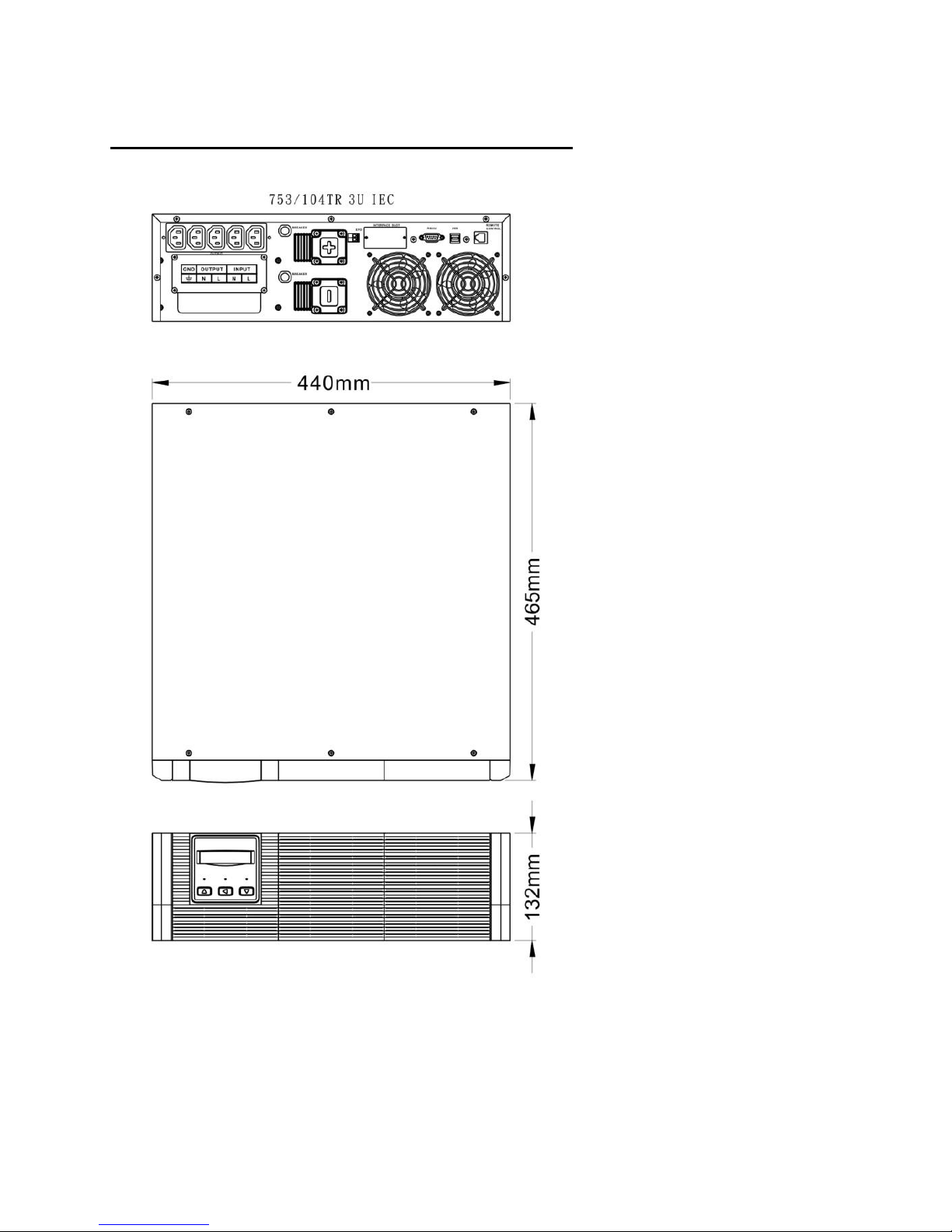
7.5KVA/ 10KVA Rack & Tower Convertible Case

14
1KVA/ 1.5KVA Rack 1U Case

15
4.2 Back View Description
650VA Tower Case
1. USB Port
5. Fan
2. Fax / Modem Surge Protection
(Option)
6. Breaker
3. Remote Control
(Detachable LCD Panel, Option)
7. Input Socket
4. Output Socket (NEMA or IEC)
16
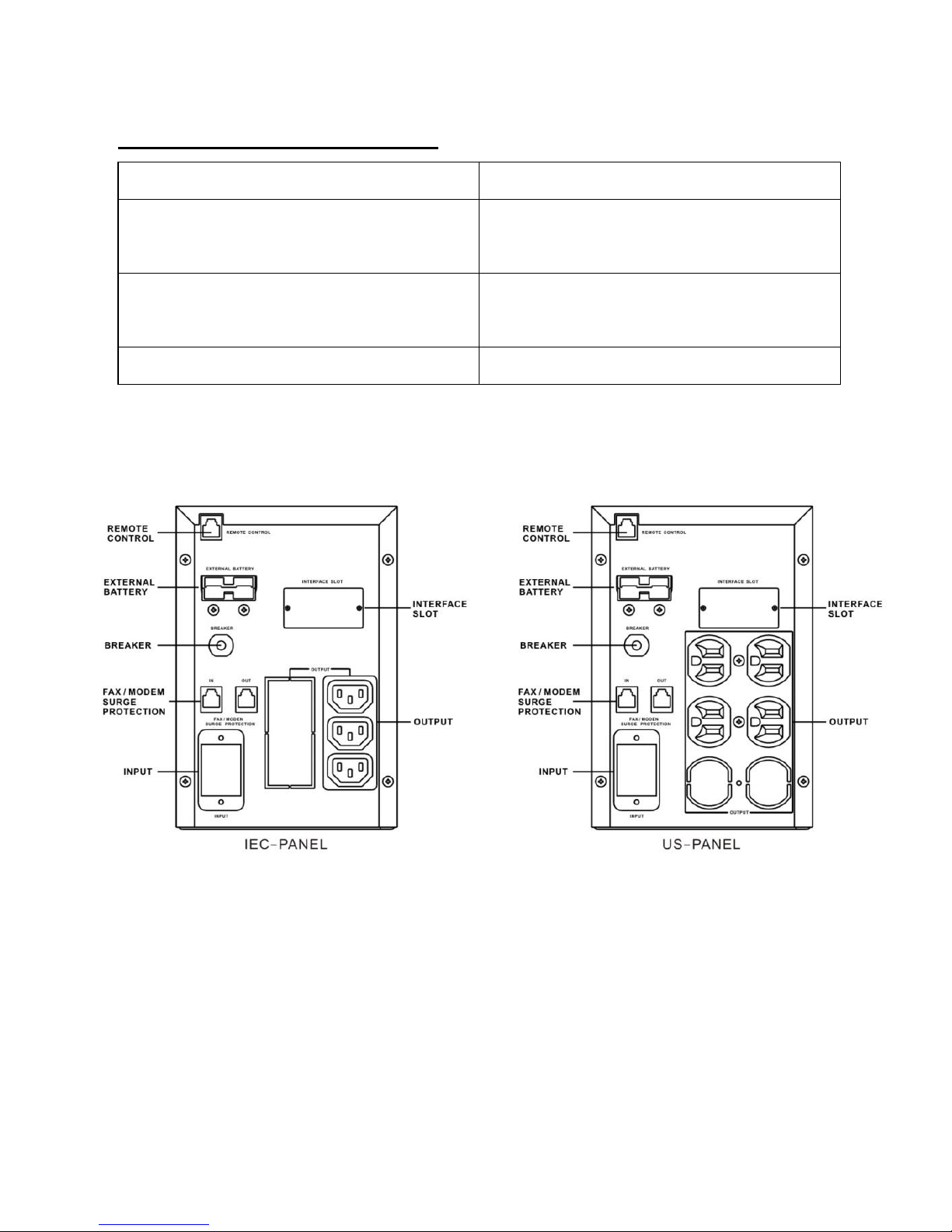
1KVA/ 1.5KVA/ 2KVA Tower Case
1. SNMP Interface Slot (Option)
5. External Battery Socket ( L )
2. Fax / Modem Surge Protection
(Option)
6. Breaker
3. Remote Control
(Detachable LCD Panel, Option)
7. Input Socket
4. Output Socket (NEMA or IEC)

17
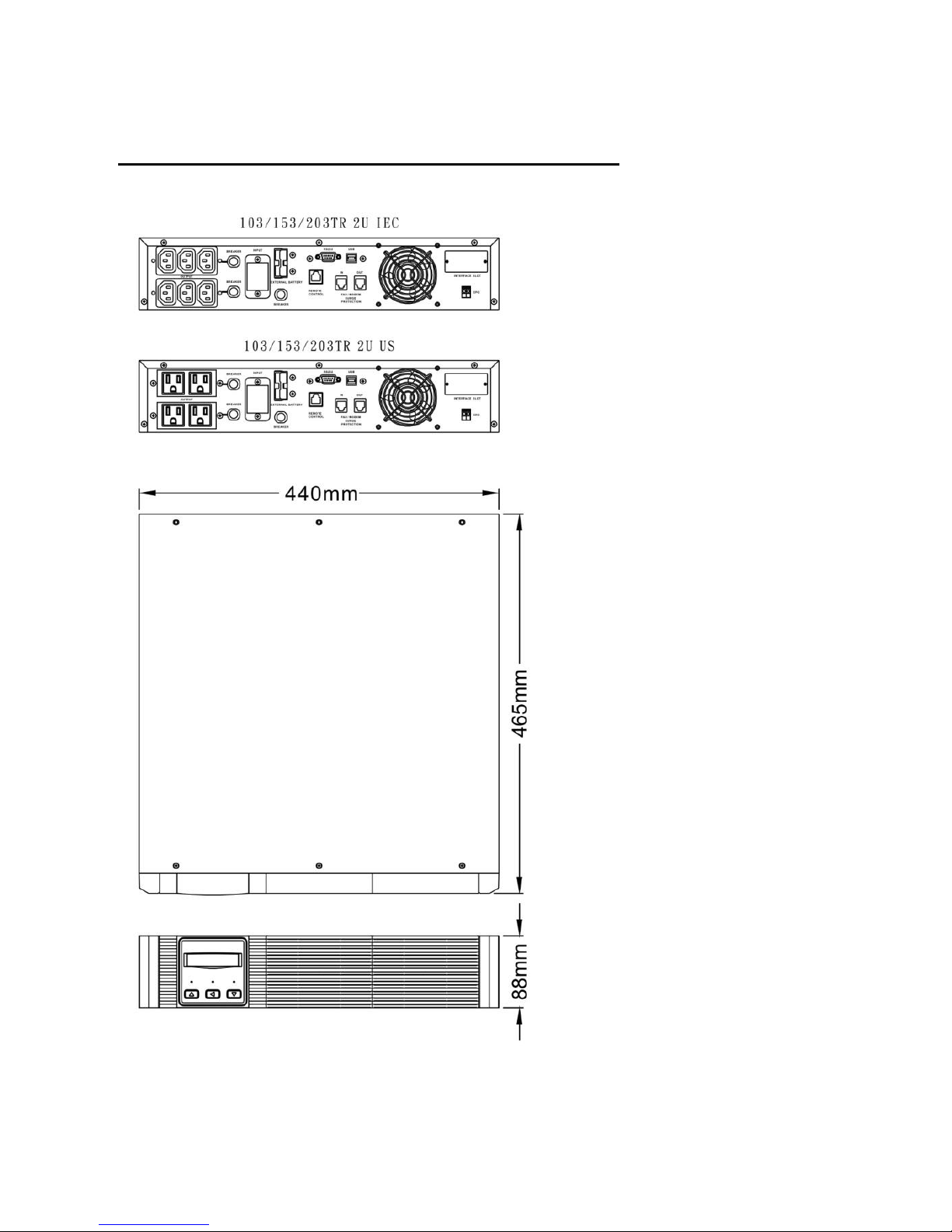
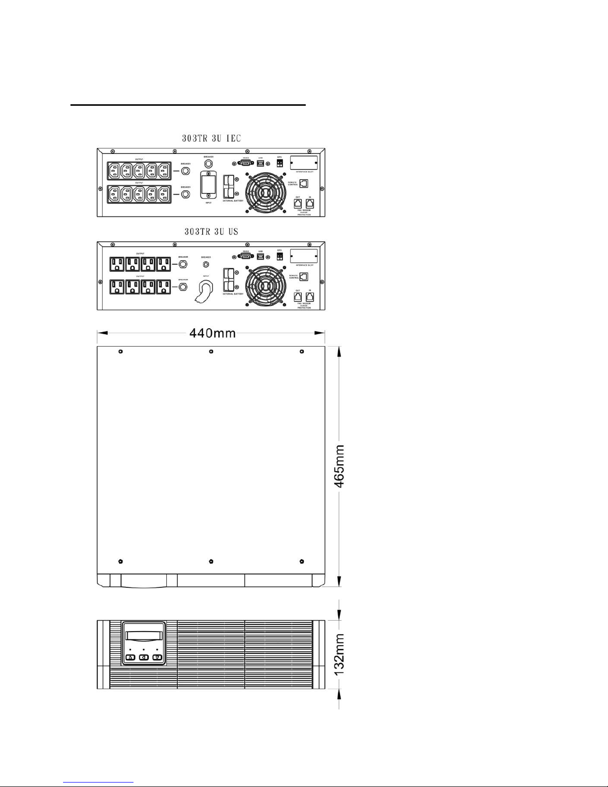
1KVA/ 1.5KVA/ 2VA Rack & Tower Convertible Case
1. RS-232 Interface Port & USB Port
(for Multi card, Option)
6. Fan
2. SNMP Interface Slot (Option)
7. External Battery Socket ( L )
3. Fax / Modem Surge Protection
(Option)
8. Breaker
4. Remote Control
(Detachable LCD Panel, Option)
9. Input Socket
5. Output Socket (NEMA or IEC)
10. EPO (Option)
18
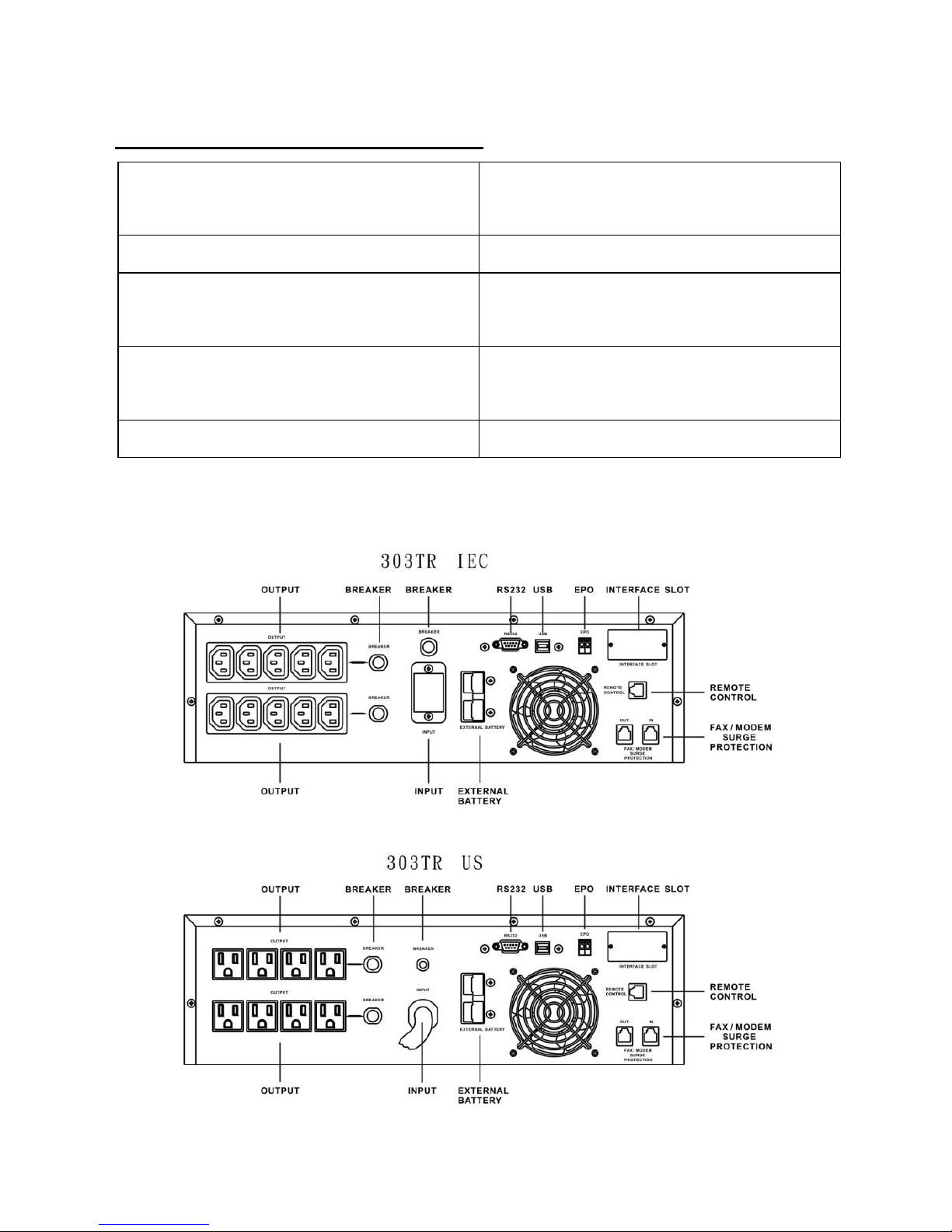
3KVA Rack & Tower Convertible Case
1. RS-232 Interface Port & USB Port
(for Multi card, Option)
6. Fan
2. SNMP Interface Slot (Option)
7. External Battery Socket ( L )
3. Fax / Modem Surge Protection
(Option)
8. Breaker
4. Remote Control
(Detachable LCD Panel, Option)
9. Input Socket
5. Output Socket (NEMA or IEC)
10. EPO (Option)

19
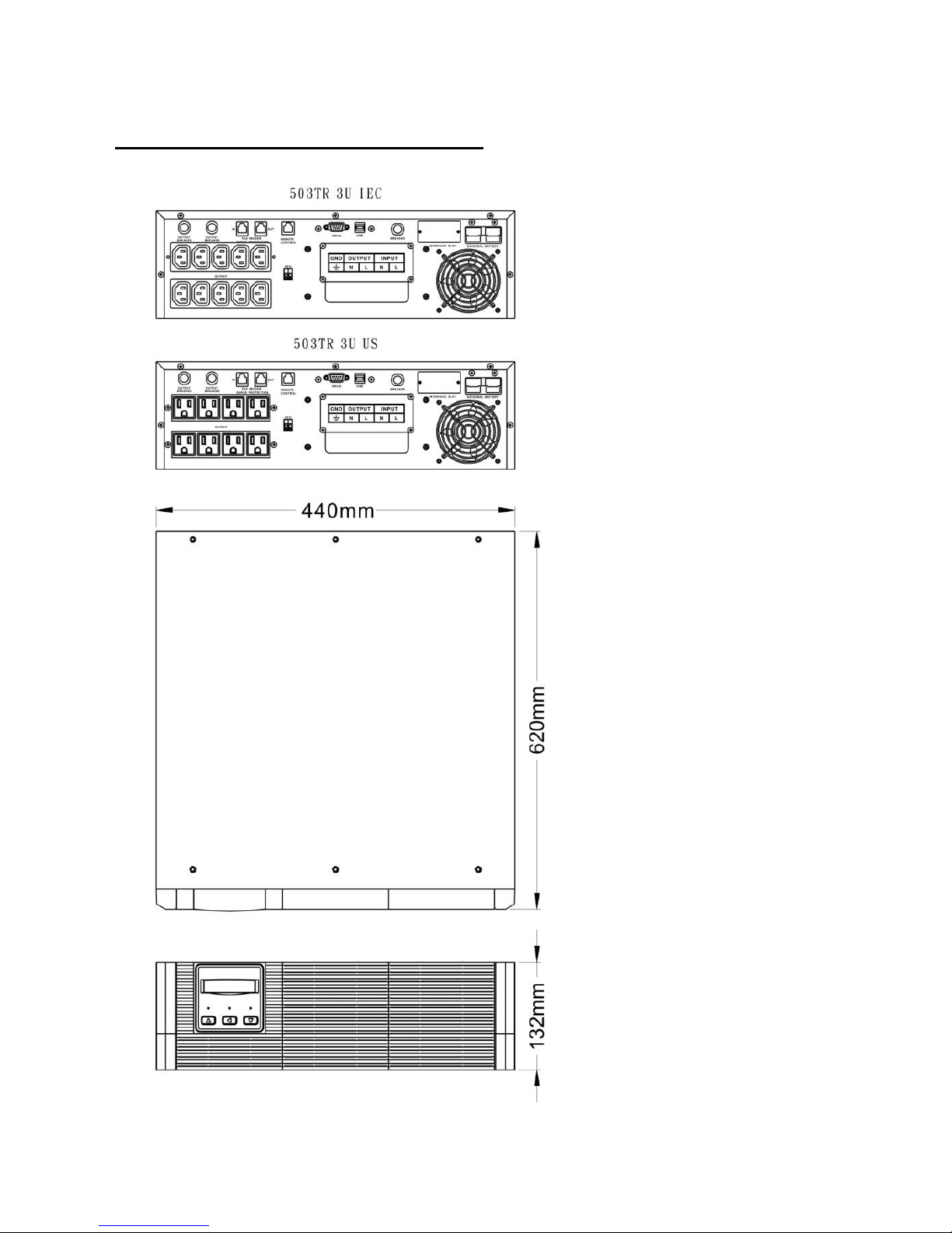
5KVA Rack & Tower Convertible Case
1. RS-232 Interface Port & USB Port
(for Multi card, Option)
6. Fan
2. SNMP Interface Slot (Option)
7. External Battery Socket ( L )
3. Fax / Modem Surge Protection
(Option)
8. Breaker
4. Remote Control
(Detachable LCD Panel, Option)
9. Terminal Block
5. Output Socket (NEMA or IEC)
10. EPO (Option)
This manual suits for next models
15
Table of contents
Popular UPS manuals by other brands


DuraComm
DuraComm RU2-1524-UPS owner's guide

HP
HP R1500 XR SERIES installation instructions

socomec
socomec Green Power 2.0 Installation and operating manual

Toshiba
Toshiba 4400 Series Installation and operation manual

Panduit
Panduit smartzone 1-3KVA user manual

Sola Hevi Duty
Sola Hevi Duty S3K2U user manual