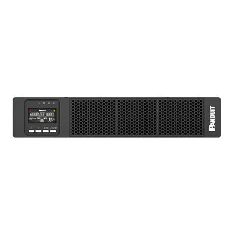
Panduit smartzone 1-3KVA User manual

User Manual V3.2
UninterruptiblePower Supply
1-3KVA(SINGLE PHASE)

SMARTZONE UPS USER MANUAL
1
Table of Contents
Section 1 – System Overview....................................................................................3
Key Features ........................................................................................................4
Basic Operations...................................................................................................5
Double Conversion Overview..............................................................................5
Line Interactive Overview....................................................................................6
UPS Modes .......................................................................................................6
Normal Mode..................................................................................................6
ECO Mode.....................................................................................................8
Convert Frequency (CF) Mode........................................................................9
Generator Mode...........................................................................................10
UPS States......................................................................................................12
Normal State................................................................................................12
ECO State....................................................................................................12
CF State ......................................................................................................12
Gen State.....................................................................................................12
AVR State....................................................................................................13
Battery State................................................................................................13
Bypass State................................................................................................13
Fault State ...................................................................................................13
Battery Test State.........................................................................................14
UPS Physical Features and Accessories...............................................................15
Physical Features ............................................................................................15
UPS Front Panel...........................................................................................15
UPS Rear Panel...........................................................................................16
UPS Accessories .............................................................................................22
External Battery Pack (UVP024, UVP036, UVP048, UVP072))........................22
Battery Cartridge ..........................................................................................23
Network Card (UNCP01)...............................................................................24
Relay Card (URC005)...................................................................................26
Section 2 – Front Panel Display (FPD) .....................................................................28
Status LEDs........................................................................................................28

SMARTZONE UPS USER MANUAL
2
Function Buttons .................................................................................................29
Turning ON/OFF the UPS....................................................................................30
Starting the UPS on Main Input Power:..............................................................30
Cold Starting the UPS (Start the UPS on Battery):..............................................30
Properly Shutting Down the UPS:......................................................................31
Color Display Operation.......................................................................................31
Monitor Operation............................................................................................31
Setup Operation...............................................................................................37
Double Conversion VRLA UPS......................................................................38
Double Conversion Li UPS............................................................................42
Line Interactive Li UPS..................................................................................46
Appendix A: 1 to 3kVA Fault Codes & Alert LEDs .....................................................49
Appendix B: Troubleshooting...................................................................................52
Appendix C: State Transitions Based on External Events.........................................54
Appendix D: Maintenance and Storage ...................................................................56
Maintenance.......................................................................................................56
Storage/Transportation........................................................................................56

SMARTZONE UPS USER MANUAL
3
Section 1 – System Overview
The Panduit SmartZone™ UPS units in this manual are line interactive or true on-line
double conversion systems that deliver highly efficient and reliable power protection for
your computer, IT, communications, and automatic equipment. These units have high
electrical performance, intelligent monitoring, and network functionality to properly
monitor and condition the world’s power anomalies (power failures, power sags, power
surges, under-voltages, over-voltages, electrical line noises, frequency variations,
switching transients, and harmonic distortion).
Each UPS comes equipped with a color display and has multiple options for interfacing
with the unit. The UPS is standardly equipped with a network card for remote network
monitoring, control, and configuration. The UPS may be optionally ordered without a
network card. Additionally, a Network Card or a Dry Contact Relay Card may be
ordered as accessories.
These UPS units support Li (Lithium-Ion) or VRLA (Valve Regulated Lead-acid)
batteries as the backup power storage system.The UPS topology of these units is
either on-line double conversion with a built-in economy (ECO) mode or line interactive.
The on-line double conversion topology supplies the best power conditioning by
recreating a true sinewave on the UPS outputs. The on-line double conversion topology
converts the input AC power to a DC power and then regenerates the AC power on the
UPS outputs. This double conversion allows the UPS to eliminate the inconsistencies in
the input power provided by the utility company. The UPS may be optionally switched to
ECO mode to increase the unit’s efficiency when the input power is known to be stable
(requires minimal conditioning).
The line interactive architecture supplies good power conditioning by monitoring the
input and adjusting the UPS outputs. Like the double conversion topology, line
interactive topology allows the UPS to eliminate most inconsistencies in the input
power, provided by the utility company. The line interactive topology compensates for
power failures, power sags, power surges, under-voltages, over-voltages, electrical line
noises, switching transients, and harmonic distortion on the input AC power. However,
the line interactive topology does not compensate for frequency variations. The line
interactive UPS provides good power conditioning with an increased efficiency.
SMARTZONE UPS USER MANUAL
4
Key Features
Integrated data center solution – All VRLA UPS units integrate with multiple
External Battery Packs (EBP), offering an excellent choice for data center
deployment.
Easy to Maintain – All UPS units support hot swappable battery cartridges. All
UPS double conversion units support options to switch to a bypass state.
Long Lasting – UPS units are available with Lithium-Ion battery cartridges for
extended battery life.
Reliable - All UPS units are controlled by Digital Signal Processors (DSPs) which
increases reliability, performance, self-protection, and self-diagnostics.
User Friendly Color Display with Color Status LEDs - allow the user to easily
set operational parameters and get UPS status.
Intelligent Monitoring Function – UPS units are standardly equipped with a
Network card for remotely controlling and monitoring the UPS via a user-friendly
Web Interface.
Load Shedding – All UPS units with outlets have one or two controllable outlet
groups may be used to shed non-critical loads while on battery backup. All UPS
units with a network card have the capability to gracefully shutdown smart loads.
EPO Function - All UPS units are equipped with an Emergency Power Off
(EPO) interface to turn OFF the UPS output via a remote dry contact switch.

SMARTZONE UPS USER MANUAL
5
Basic Operations
The basic operations of a double conversion UPS are explained through the high-level
generic block diagram in Figure 1. The generic diagram is only used for a simple high-
level explanation of the UPS working modes and operating states. This block diagram is
not the actual block diagram of the UPS units.
The basic operations of a line Interactive UPS are explained through the high-level
generic block diagram in Figure 2. The generic diagram is only used for simple high-
level explanation of the UPS working modes and operating states. This block diagram is
not the actual block diagram of the UPS units.
Double Conversion Overview
The UPS input is connected to an AC power source via an input plug. The output is
connected to loads via outlets on the UPS. The load may be powered from the input
source (directly or through the rectifier/inverter) or the battery(through the inverter).The
UPS power-switching circuitry may be isolated from the power chain while continuing to
power the load (ECO Mode or bypass state).The following UPS Modes and UPS States
sections use the simplified block diagram to help explain the modes and states of the
UPS.
Figure 1: High-Level Generic Double Conversion UPS Block Diagram

SMARTZONE UPS USER MANUAL
6
Line Interactive Overview
The UPS input is connected to an AC power source via an input plug. The output is
connected to loads via outlets on the UPS. The load may be powered from the input
source (through the Automatic Voltage Regulation (AVR) – boost/buck circuitry) or the
battery (through the inverter).The following block diagram explains the UPS Modes and
UPS States described in the sections below.
Figure 2: High-Level Generic Line Interactive UPS Block Diagram
UPS Modes
The double conversion UPS may be configured into four different working modes. The
line interactive UPS may be configured into two different working modes. This section
explains these settable working modes. The UPS working mode is manually configured
into the UPS at setup time. The selected mode will become the Default state of the UPS
until the working mode is manually changed.
Normal Mode
Double Conversion
Normal mode is the default working mode of the double conversion UPS units. When
the UPS is operating in Normal mode, it provides a stable pure sinusoidal AC power
output and charges or maintains the charge on the battery. In Normal mode, the input
and output relays are closed, and the bypass relay is open. The rectifier/charger derives
power from the AC Input and supplies DC power to the inverter while simultaneously
charging or maintaining the charge on the battery. The inverter inverts the DC power to
AC power and supplies it to the load with a stable pure sinusoidal AC waveform.

SMARTZONE UPS USER MANUAL
7
If the input power is lost or has anomalies outside of the set ranges while the UPS is
operating in Normal mode:
The batteries will stop charging (input relay will open)
The bypass relay will remain opened
The output relay will remain closed
The battery will start providing the DC power to the DC to AC inverter, continuing
to provide uninterrupted AC power to the load
The UPS is now in the Battery state and will indicate an alarm; the UPS will continue to
provide power to the load for a limited time (runtime of the battery backup system
connected to the UPS for the percentage of load connected).
If an internal or an external output power event occurs while operating in Normal mode:
The input relay may open (depending on the internal event)
The output relay will open
The bypass relay will close (assuming the input is not outside of the input bypass
range), continuing to provide minimally conditioned AC power to the load.
The UPS is now in the Bypass state and will indicate an alarm. Refer to Appendix C:
State Transitions Based on External Events for state transitions based on
input/output events.
Note: This unit does have short-circuit protection but only when power is being provided
to the load through the inverter. If the unit is in ECO mode or in the bypass state when a
short-circuit occurs on the output of the UPS, the UPS unit may be damaged.
Line Interactive
Normal mode is the default working mode of the line interactive UPS units. When the
UPS is operating in Normal mode it provides a stable AC power output. The batteryis
always being charged or maintained if there is input power within range. In Normal
mode, the input and output relays are closed, and the INV relay is switched away from
the inverter. In this state the input power is filtered and provided directly to the load. If
the input voltage is surging or sagging, the UPS will transition to the AVR state. In the
AVR state,if the input voltage needs to be increased, the boost and buck relays will be
in the boost position (up). If the input voltage needs to be decreased, the boost and
buck relays will be in the buck position (down).
If the input power is lost or has anomalies are outside of the set ranges while the UPS is

SMARTZONE UPS USER MANUAL
8
operating in Normal mode, the INV relay will switch to the inverter and the batterywill
continue to provide uninterrupted AC power to the load through the inverter. The UPS is
now in the Battery state; the UPS will continue to provide power to the load for a limited
time (runtime of the battery backup system connected to the UPS for the percentage of
load connected).
If an internal or an external output event occurs while operating in Normal mode, the
input relay remains closed, the INV relay may switch to the inverter (depending on the
internal or external event), and the output relay may open (depending on the internal or
external event). Power may be lost to the load. Refer to Appendix C: State
Transitions Based on External Events for state transitions based on input/output
events.
Note: This unit does have short-circuit protection but only when power is being provided
to the load through the inverter (from the battery).If the unit is in Normal mode when a
short-circuit occurs on the output of the UPS, the UPS unit may be damaged.
ECO Mode
This mode is only supported on the on-line double conversion UPS units. When the
UPS is in Normal mode and the power requirements for the load are not critical and the
input source is stable (no power anomalies), the UPS may be set to Energy Savings
(ECO) mode to increase the efficiency of the power supplied through the UPS. In ECO
mode, all voltage increases and decreases will be passed along to the load.
Additionally, any frequency variations on the input will get passed on to the load. When
the UPS is manually configured for ECO mode, the output relay opens, and the bypass
relay closes. The input relay remains closed, continuing to keep the backup batteries
charged. When the UPS is in ECO mode, the source power is minimally conditioned.
If the input power is lost while the UPS is operating in ECO mode:
The batteries will stop charging (input relay will open)
The bypass relay will open
The output relay will close
The battery will start providing the DC power to the DC to AC inverter, continuing
to provide uninterrupted AC power to the load.
The UPS is now in the Battery State. When the UPS is operating in ECO mode, if the
input power has any anomaly (power sags, power surges, under-voltages, over-
voltages, electrical line noises, frequency variations, switching transients, and harmonic
distortion) that are outside of the bypass set ranges:

SMARTZONE UPS USER MANUAL
9
The input relay will remain closed (continuing to charge the battery– assuming
the anomaly is still within the operating range of the UPS)
The bypass relay will open
The output relay will close
The rectifier will start providing the DC power to the DC to AC inverter, continuing
to provide uninterrupted AC power to the load.
The UPS is now in the Normal state. If the anomaly is outside of the UPS operating
range, then the UPS will transition to the Battery state. Refer to Appendix C: State
Transitions Based on External Events for state transitions based on input/output
events.
If an internal or an external output event occurs while operating in ECO mode, the
bypass relays will open, the input relay will open and the output will shut down. AC
power to the load will be lost.
Note: This unit does have short-circuitprotection but only when power is being provided
to the load through the inverter. If the unit is in ECO mode or in the bypass state when a
short-circuit occurs on the output of the UPS, the UPS unit may be damaged.
Convert Frequency (CF) Mode
This mode is only supported on the on-line double conversion UPS units. The UPS may
be set to CF mode to increase the allowable input frequency range of the UPS while
maintaining the desired output frequency. Setting the UPS to CF mode requires the
UPS unit to be derated. The 1-3kVA UPS units in CF mode are derated to 80% of the
maximum output but will maintain a 50Hz output frequency with an input frequency from
46Hz to 54Hz, or a 60Hz output frequency with an input frequency from 56Hz to 64Hz.
When CF mode is set, the Bypass state is automatically disabled (the unit cannot switch
to the Bypass state under any conditions, and frequency conversion is not supported
through the bypass path).
If the input power is lost or has any anomalies outside of the set ranges while the UPS
is operating in CF mode:
The batteries may stop charging (input relay will open)
The bypass relay will remain opened
The output relay will remain closed
The battery will start providing the DC power to the DC to AC inverter, continuing
to provide uninterrupted AC power to the load.

SMARTZONE UPS USER MANUAL
10
The UPS is now in the Battery state; the UPS will continue to provide power to the load
for a limited time (runtime of the battery backup system connected to the UPS for the
percentage of load connected). Refer to Appendix C: State Transitions Based on
External Events for state transitions based on input/output events.
If an internal or an external output event occurs while operating in CF mode, the output
relay will open and the output will shut down, AC power to the load will be lost.
Generator Mode
Double Conversion
The UPS may be set to Generator mode to enable the UPS to have a wider input
frequency range (40Hz to 70Hz). Setting the double conversion UPS to Generator mode
requires the UPS unit to be derated. The 1-3kVA double conversion UPS units in
Generator mode are derated to 75% of the maximum output but will maintain a 50Hz or
60Hz output frequency over the full input frequency range.
Note: The Generator mode is not saved on the 1-3kVA UPS units; when the 1-3kVA
UPS unit is powered OFF and restarted, the units will restart in Normal mode.
If the input power is lost or has input anomalies outside of the operating range of the
UPS while the UPS is operating in Generator mode:
The batteries will stop charging (input relay will open)
The bypass relay will remain opened
The output relay will remain closed and the battery will start providing the DC
power to the DC to AC inverter, continuing to provide uninterrupted AC power to
the load.
The UPS is now in the Battery state; the UPS will continue to provide power to the load
for a limited time (runtime of the battery backup system connected to the UPS for the
percentage of load connected).
If an internal or an external output event occurs while operating in Generator mode, the
input and output relays open and the bypass relay closes (assuming the input is not
outside of the input bypass range), continuing to provide unconditioned AC power to the
load.
The UPS is now in the Bypass state with no frequency or voltage conditioning. Output
frequency and voltage will equal input frequency and voltage. Refer to Appendix C:
State Transitions Based on External Events for state transitions based on

SMARTZONE UPS USER MANUAL
11
input/output events.
Line Interactive
The UPS may be set to Generator mode to enable the UPS to have a wider input
frequency range (40Hz to 70Hz). Setting the line interactive UPS to Generator mode will
not require the UPS unit to be derated. The 1-3kVA line interactive UPS units does not
perform frequency conversion. The output frequency will be the same as the input
frequency.
Note: The Generator mode is not saved on the 1-3kVA UPS units; when the 1-3kVA
UPS unit is powered OFF and restarted, the units will restart in Normal mode.
If the input power is lost or has input anomalies outside of the operating range of the
UPS while the UPS is operating in Generator mode:
The input relay will open
The INV relay will switch to inverter
The output relay will remain closed
The battery will start providing the DC power to the DC to AC inverter, continuing
to provide uninterrupted AC power to the load.
The UPS is now in the Battery state. The UPS will continue to provide power to the load
for a limited time (runtime of the battery backup system connected to the UPS for the
percentage of load connected).
If an internal or an external output event occurs while operating in Generator mode, the
input relay may open (depending on the internal fault) and the INV relay will switch to
inverter (depending on the external fault), continuing to provide conditioned AC power to
the load.
The UPS is now in the Battery state. The UPS will continue to provide power to the load
for a limited time (runtime of the battery backup system connected to the UPS for the
percentage of load connected). If the external fault is an overload, the output replay will
open and power to the load will be lost. Refer to Appendix C: State Transitions
Based on External Events for state transitions based on input/output events.
Note: This unit does have short-circuitprotection but only when power is being provided
to the load through the inverter. If the unit is in Generator mode or in the bypass state
when a short-circuit occurs on the output of the UPS, the UPS unit may be damaged.

SMARTZONE UPS USER MANUAL
12
UPS States
The UPS automatically transitions to different states based on internal or external
events; the user may also force the UPS into some statesthrough one of the user
interfaces. There are eight different states that the UPS may be in. Refer to Appendix
C: State Transitions Based on External Events for state transitions based on
input/output events.
Normal State
The UPS will go into the normal statewhen the UPS is set to Normal Mode at setup
time. This is the default mode and state that the UPS will power up in on new units from
the factory.If the UPS is set for Normal Mode, the Normal state is the default state
where the UPS will return to after the internal or external event has been cleared or the
forced state has expired.
If an internal or external event occurs while operating in the normal state, the UPS will
automatically transition to battery, bypass, fault, or battery test state depending on the
event.
ECO State
The UPS will go into the ECO state when the UPS is set to ECO Mode at setup time. If
the UPS is set for ECO Mode, the ECO state is the default state where the UPS will
return to after the internal or external event has been cleared or the forced state has
expired.
If an internal or external event occurs while operating in the ECO state, the UPS will
automatically transition to battery, fault, or batterytest state depending on the event.
CF State
The UPS will go into CF state when the UPS is set to CF Mode at setup time. If the UPS
is set for CF Mode, the CF state is the default state where the UPS will return to after
the internal or external event has been cleared or the forced state has expired.
If an internal or external event occurs while operating in the CF state, the UPS will
automatically transition to battery, bypass, fault, or battery test state depending on the
event.
Gen State
The UPS will go into Gen state when the UPS is set to Generator Mode at setup time. If
the UPS is set for Generator Mode, the Gen state is where the UPS will return to after
the internal or external event has been cleared or the forced state has expired.

SMARTZONE UPS USER MANUAL
13
If an internal or external event occurs while operating in the Gen state, the UPS will
automatically transition to battery, bypass, fault, or battery test state depending on the
event.
AVR State
This state is only supported on the line interactive UPS units. The UPS automatically
transitions to the Automatic Voltage Regulation (AVR) state when the input voltage goes
outside of the set input voltage range (refer to Appendix C: State Transitions Based
on External Events). The UPS will automatically return to the default state when the
input source recovers.
If an internal or external output event occurs while operating in the AVR state, the UPS
will transition to the Batterystate and continue to provide power to the load for a limited
time (until the battery hits its EOD).
Battery State
The UPS automatically transitions to the battery state with no power interruption to the
load when input power is out of the operating range or power is lost. The UPS will
automatically return to the default state when the input source recovers.
If an internal or external output event occurs while operating in the battery state, the
output will shut down. AC power to the load will be lost.
Bypass State
The UPS may automatically transition to the bypass state with no power interruption
when an internal or an external output event occurs (depending on the event). The UPS
may also be set to the bypass state by turning the invertor OFF, but the input voltage
and frequency must be within the specified upper and lower limits of the bypass as
specified during the UPS setup. For 1-3kVA UPS units, press the ON/OFF button on the
Front Panel Display to turn off the inverter and force the UPS into the bypass state.
While the UPS is in the bypass state, the source power is not fully conditioned as in the
Normal, CF, or Gen state;most variations in frequency and voltage will get passed on to
the load.
If another internal or an external output event occurs while operating in the bypass
state,the UPS will transition to the Fault state and the output will shut down. AC power
to the load will be lost.
Fault State
The UPS automatically transitions into the fault state when the UPS is unable to provide
power to the load. The input, output, and bypass relays will all open. If the fault clears,

SMARTZONE UPS USER MANUAL
14
the UPS should transition back to the Default state (depending on the fault that is
cleared).
Battery Test State
The UPS may be manually or automatically put into the battery test state, but the UPS
will automatically transition back to the default state when the test is complete. The
battery test will automatically run when the UPS is powered ON and periodically while
the unit is operating. The battery test may also be manually executed at any time. The
frequency and duration of the batterytest may have an impact on the batterylife. All
battery tests are preset for a duration of 10 seconds. The user can select the frequency
of the test. The battery test may be automated through the network card on all 1-3kVA
UPS units.
The 1-3kVA UPS does not go into the battery state when the battery test is run. The
UPS stays in the default state for powering the load, but the battery charger is turned
OFF and the battery discharges for 10 seconds through an internal load. If the battery is
damaged or disconnected, the UPS presents a No Battery Alarm, which means the user
should replace the battery or check the battery connection. The UPS will automatically
turn the battery charge back ON when the batterytest completes.

SMARTZONE UPS USER MANUAL
15
UPS Physical FeaturesandAccessories
The following sections provide an overview of the human and electrical interfaces on the
UPS unit. All UPS units are rack mountable with a display on the front side of the unit.
Physical Features
UPS Front Panel
The UPS Front Panel for all 1-3kVA Models are the same. Air flow vents occupy ¾ of
the front panel and a display module occupies the left ¼ of the front panel. The front
panel display module contains four status LEDs, a 2.8-inch segmented color display
and four function buttons.
Figure 3: 1-3kVA Font Panel
Air Flow Vents
The air flow vents are critical to the operation of the UPS unit. These vents must remain
clean and clear of all objects that may restrict the air flow through the UPS unit.
Status LEDs
Each unit has four Status LEDs, Normal LED (green), Battery LED (yellow), Bypass
LED (blue), and Alert LED (red/yellow). These LEDs provide a quick high-level view of
the unit’s operating conditions. Refer to UPS Front Panel section for further details.
Color Display
The unit has a 2.8-inch segment color display. This display is used for monitoring,
control, and configuration. The display may be manually rotated to the orientation of the
unit. Remove the UPS faceplate, rotatethe screen ¼ turn and then reinstall the UPS
faceplate.
Function Buttons
The UPS has four function buttons, the UP button, the DOWN button, the CANCEL/OFF
button, and the ENTER/ON/MUTE button. These buttons are used to navigate the
Monitor and the Setup screens, used to change settings, used to turn ON/OFF the UPS

SMARTZONE UPS USER MANUAL
16
and used to mute/unmutethe audio alerts.
UPS Rear Panel
The rear panel varies based on the model of the UPS unit. Refer to the UPS Physical
Feature call out table and the Model specific figures in this section for details. The rear
panels of models may change, refer to the Customer Drawing for the latest view of the
rear panel of a specific UPS unit.
1 to 3kVA 1-Phase UPS Physical Feature Call Out Table:
1. Input Power Cord
5. Intelligent Slot
9. USB Communications
2. Input Circuit Breaker
6.Net Surge Protection Ports
10. Chassis Ground Point
3. Output Receptacles
7. EPO Signal Port
11. Output Circuit Breakers
4. EBP Connection
8. RS232 Communication
Input Power Cord (INPUT)
Each UPS Model may have unique power input connector, labeled INPUT on the back
of the unit. Refer to the corresponding Product Specification Sheet for detailed
definition.
Input Circuit Breaker (BREAKER)
All UPS units have an input circuit breaker to protect form overload conditions, labeled
BREAKER with a line to the input interface on the back of the unit. Refer to the
corresponding Customer Documentation for details.
Output Receptacles
Each UPS Model has unique groups of power output connectors, labeled GROUP 1 and
GROUP 2. The figures in this section show output receptacle types per SKU. Refer to
the corresponding Product Specification Sheet for latest detailed definition.
EBP Connection (+ xxVDC -)
Each VRLA UPS unit has an External Battery Pack (EBP) power connection, labeled
with + 24VDC -, + 36VDC -, + 48VDC -, or + 72VDC – on the back of the unit. These
UPS Model have been calibrated to a specific EBP and EBP Operating Voltage. These
EBP units are not interchangeable between UPS units with different KVAs. Note: The Li
UPS units do not support External Battery Pack (EBP) units.
Intelligent Slot (INTELLIGENT SLOT)
Each UPS unit is standardly equipped with a Network Management Card installed in the
intelligent slot, labeled INTELLIGENT SLOT on the back of the unit. Alternatively, the
UPS may be ordered with an empty Intelligent Slot, and later updated with a UPS

SMARTZONE UPS USER MANUAL
17
Network Management Card or a UPS Relay Card.
Network Surge Protection Ports (RJ45 NET SURGE PROTECTION)
Each UPS unit comes equipped with an internal Network/Fax/Modem Surge protection
module, labeled RJ45 NET SURGE PROTECTION on the back of the unit. The module
includes RJ45 pass-through ports, either port may be used for input or output.
EPO Signal Port (EPO)
Each UPS unit comes equipped with an Emergency Power Off Signal Port, labeled EPO
on the back of the unit. The UPS comes equipped with a 2-pin plug wired to provide a
short that results in normal UPS operation.
CAUTION!
IF THE PLUG OR SHORTING WIRE IS REMOVED, THE UPS
SYSTEM WILL BE COMMANDED TO SHUT DOWN. IN TYPICAL
APPLICATIONS, THE PLUG WILL BE WIRED TO A REMOTE
NORMALLY CLOSED DRY CONTACT TO PROVIDE A SHORT
FOR NORMAL OPERATION. THE REMOTE DRY CONTACT
COULD BE OPENED TO COMMAND THE UPS TO SHUT DOWN
IN AN EMERGENCY.
DB9 Coms Port (RS232)
All units have a DB9 equipped with RS232 serial communications port, labeled RS232
on the back of the unit. This serial port is reserved for UPS core Firmware Update.
USB Coms Port (USB)
All units have a USB serial communications port, labeled USB on the back of the unit.
This communication port is reserved for “Future Use”.
Chassis Ground Connection Point ( )
All units have a chassis ground connection, labeled with a ground symbol on the back of
the unit. This is used to ground the UPS and EBP chassis to the rack/cabinet. For safety
and proper grounding procedures, this grounding connection point must be connected
to the rack/cabinet ground. Refer to the UPS Installation Manual for proper connections
to this ground.

SMARTZONE UPS USER MANUAL
18
Output Circuit Breakers (BREAKER)
Some UPS units have output circuit breakers to protect from load overload conditions,
labeled with BREAKER and a line to the outlet group it protects on the back of the unit.
Refer to the corresponding Customer Documentation for details.
1kVA North America Model Rear Panels (U01x11V / U01x13V / U01x11L)
The 1kVA North American (NA) UPS units have a permanently connected input power
cord with a NEMA 5-15 plug. These units have two groups of outlets. Group 1 (4x 5-
15R) outlets are the main outlets that are not switchable. These outlets should contain
the critical loads. Group 2 (2x 5-15R) are switchable outlets. These outlets could contain
the non-critical loads. When the UPS is operating in the batterystate, Group 2 outlets
may be programmed to turn off earlier to conserve battery capacity for the Group 1
outlets.
Figure 4: 1kVA VRLA NA Rear Panel View (U01x11V & U01x13V)
Figure 5: 1kVA Li NA Rear Panel View (U01x11L)
2kVA and 1.5kVA North America Model Rear Panels (U02x11V / U02x11L)
The 2kVA VRLA unit has a permanently connected input power cord with a NEMA 5-
20P plug. The 1.5kVA Li unit has a permanently connected input power cord with a

SMARTZONE UPS USER MANUAL
19
NEMA 5-15P plug. These units have two groups of outlets. For the 2kVA VRLA UPS
unit Group 1 (4x 5-20R) outlets are the main outlets that are not switchable, and Group
2 (2x 5-20R) are switchable outlets. For the 1.5kVA Li UPS unit Group 1 (4x 5-15R)
outlets are the main outlets that are not switchable, and Group 2 (2x 5-15R) are
switchable outlets. Group 1 outlets should contain the critical loads and Group 2 outlets
could contain the non-critical loads. When the UPS is operating in the battery state,
Group 2 outlets may be programmed to turn off earlier to conserve battery capacity for
the Group 1 outlets.
Figure 6: 2kVA VRLA NA Rear Panel View (U02x11V)
Figure 7: 1.5kVA Li NA Rear Panel View (U02x11L)
3kVA North America Model Rear Panels (U03x11V / U03x11L)
The 3kVA NA UPS units have a permanently connected input power cord with a NEMA
L5-30 plug. These units have two groups of outlets. Group 1 (2x 5-20R and 1x L5-30R)
outlets are the main outlets that are not switchable. These outlets should contain the
critical loads. Group 2 (2x 5-20R) outlets are switchable. These outlets could contain the
non-critical loads. When the UPS is operating in the battery state, Group 2 outlets may
be programmed to turn off earlier to conserve batterycapacity for the Group 1 outlets.
Table of contents
Other Panduit UPS manuals

Panduit
Panduit UPS003LSM User manual

Panduit
Panduit SmartZone User manual

Panduit
Panduit smartzone 5-10KVA User manual

Panduit
Panduit UPS003024024015 User manual

Panduit
Panduit UPS003LSM User manual

Panduit
Panduit smartzone U01N11L User manual

Panduit
Panduit Smartzone U01N11V User manual

Panduit
Panduit UPS00100DC User manual

Panduit
Panduit SmartZone User manual
Popular UPS manuals by other brands

CyberPower
CyberPower Paragon OL1500RMXL2U Specification sheet

Eaton
Eaton Powerware 9390 Installation and operation manual

MGE UPS Systems
MGE UPS Systems Pulsar ellipse 1200 Installation and user manual

MGE UPS Systems
MGE UPS Systems PULSAR 1000 Installation and user manual

GE
GE Power Supply user manual

Aros
Aros Flexus FM Series user manual