ATI Technologies B14 User manual

Fax: 610-917-0992 Fax: +44 (0)1457-874-468
O&MManual
B14
MonitorSystem
HomeOfficeEuropeanOffice
AnalyticalTechnology, Inc.ATI(UK)Limited
6Iron BridgeDriveUnit 1& 2GateheadBusiness Park
Collegeville, PA 19426 Delph NewRoad, Delph
Phone: 800-959-0299 SaddleworthOL3 5DE
610-917-0991Phone: +44 (0)1457-873-318
Fax: 610-917-0992Fax: +44(0)1457-874-468
Email: sales@analyticaltechnology.com Email: sales@atiuk.com
Web: www.Analyticaltechnology.com

O&M Manual
Rev-P(7/15)2
TABLEOFCONTENTS
INTRODUCTION.......................................................................................................................................................4
B12 SENSOR/TRANSMITTER .......................................................................................................................................5
B14 RECEIVER MODULE.............................................................................................................................................5
A17 POWER SUPPLY MODULE....................................................................................................................................5
NEMA 4X ENCLOSURE..............................................................................................................................................5
EXPLOSION-PROOF ENCLOSURES................................................................................................................................5
A UDIBLE HORN ..........................................................................................................................................................6
S TROBE LAMP ............................................................................................................................................................6
A19 BATTERY BACK-UP.............................................................................................................................................6
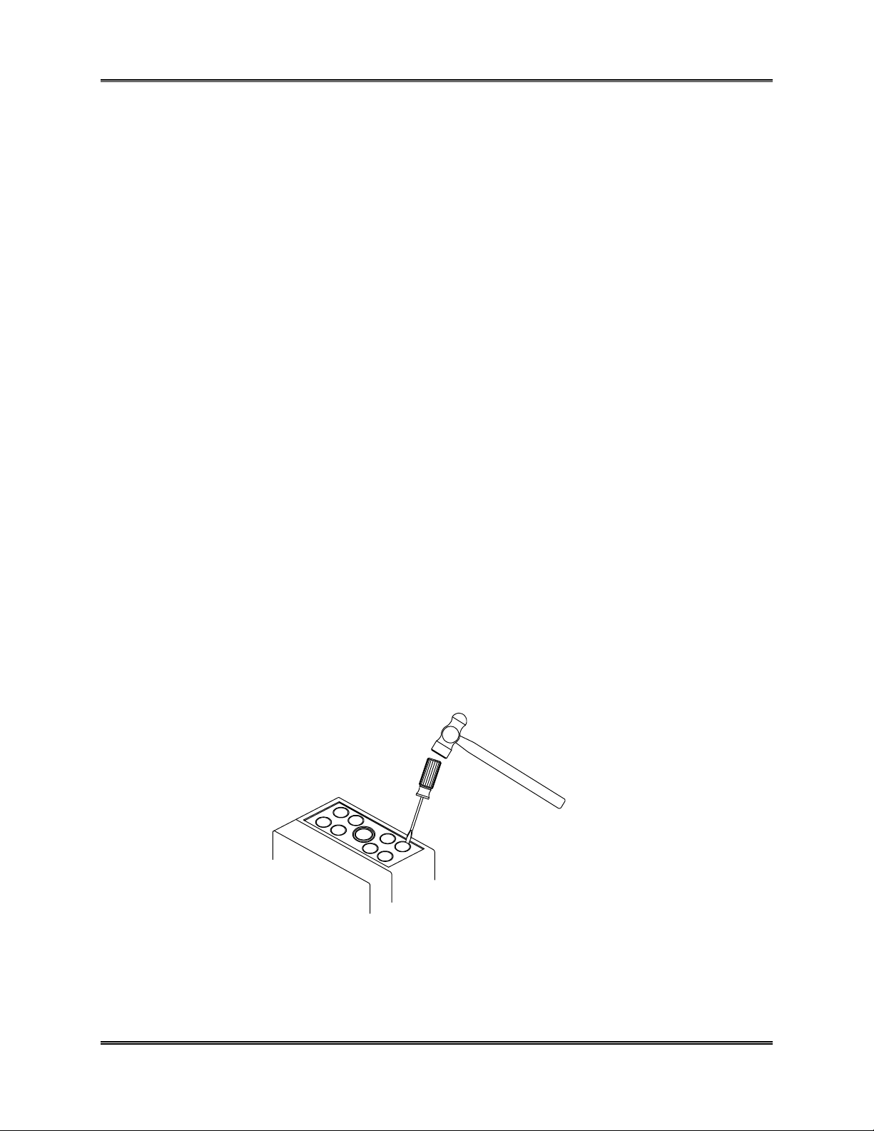
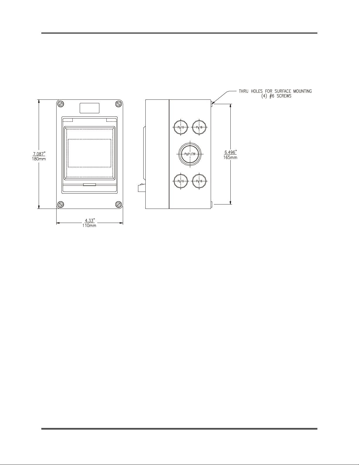
MECHANICALINSTALLATION...........................................................................................................................7
ELECTRICALINSTALLATION..........................................................................................................................12
B14 RECEIVERMODULE.....................................................................................................................................24
ELECTRICAL CONNECTION .......................................................................................................................................24
FACTORY CONFIGURATION ......................................................................................................................................26
CONFIGURATION SWITCHES .....................................................................................................................................27
OPERATING RANGE CHART ......................................................................................................................................28
SETPOINT SELECTION ...............................................................................................................................................29
RANGE SELECTION ...................................................................................................................................................30
RELAY CONFIGURATION...........................................................................................................................................30
EXTERNAL HORN RELAY..........................................................................................................................................31
OPERATION.............................................................................................................................................................32
ALARM ACKNOWLEDGEAND RESET ........................................................................................................................32
TROUBLE ALARM AND RELAY..................................................................................................................................33
LAMPAND HORN TEST.............................................................................................................................................33
INHIBIT MODE ..........................................................................................................................................................33
REMOTE RESET.........................................................................................................................................................34
ANALOG OUTPUT .....................................................................................................................................................34
TROUBLESHOOTING..................................................................................................................................................34
RECEIVER MODULE PARTS LIST......................................................................................................................35
UNIVERSALPOWERSUPPLY.............................................................................................................................36
CAUTION ...............................................................................................................................................................36
POWER SUPPLY PARTS LIST.............................................................................................................................38
BATTERY BACK-UP UNIT..................................................................................................................................39
INSTALLATION..........................................................................................................................................................39
OPERATION...............................................................................................................................................................40
REMOVALFROM SERVICE.........................................................................................................................................40
BATTERY BACK-UP PARTS LIST......................................................................................................................41
STROBELIGHT......................................................................................................................................................42
STROBE PARTS LIST............................................................................................................................................43

O&M Manual
Rev-P(7/15)3
TABLEOFFIGURES
Figure1 -SingleModuleSystemEnclosure Dimensions(80-0005)............................................................ 8
Figure2 -TwoModule SystemEnclosure Dimensions(80-0006)............................................................... 9
Figure3 -Three ModuleSystemEnclosure Dimensions(80-0007).......................................................... 10
Figure4 -SixModuleSystemEnclosure Dimensions(80-0008)............................................................... 11
Figure5 -SinglePoint ReceiverInternalWiring (ATI-0172)...................................................................... 12
Figure6 -DualPoint ReceiverInternalWiring (ATI-0173)......................................................................... 13
Figure7 -FourPoint ReceiverInternalWiring (ATI-0174)......................................................................... 14
Figure8 -ReceiverConnectionto 65WPowerSupply(ATI-0545)............................................................ 15
Figure9 -TypicalSystemWiring, Nemz-4 TransmitterVersion (ATI-0175).............................................. 16
Figure10 -TypicalSystemWiring, Explosion-ProofB12 Sensor/Transmitter(ATI-0176)........................ 17
Figure11 -TypicalSystemWiring, B12-17 Combustible Sensor/Transmitter(ATI-0215)......................... 18
Figure12 -TypicalSystemWiring, C12-17 Combustible Sensor/Transmitter(ATI-0609)........................ 19
Figure13 -TypicalSystemWiring, A12 2-WireTransmitter(ATI-0179).................................................... 20
Figure14 -TypicalSystemWiring, A12-17 Combustible Transmitter(ATI-0355)..................................... 21
Figure15 -TypicalSystemWiring, D12 Transmitter(2-Wire Hookup)(ATI-0610)................................... 22
Figure16 -TypicalSystemWiring, D12 Transmitter(3-Wire Hookup)(ATI-0611).................................... 23
Figure17 -Front PanelControls&LEDs(ATI-0177)................................................................................. 24
Figure18 -ReceiverModule Terminals(ATI-0178)................................................................................... 25
Figure19 -Configuration BoardSwitchLocation....................................................................................... 28
Figure20 -PowerSupplyTerminalConnections(ATI-030)....................................................................... 37
Figure21 -BatteryBack-up Mounting Dimensions.................................................................................... 39
Figure22 -ExternalStrobe Light Connections(ATI-0202)........................................................................ 42

ATI B14AlarmSystemSection 1-Overview
O&M Manual
Rev-P(7/15)4
INTRODUCTION
The B14 isan on-linemonitoring systemforthe detection ofhazardousgasesinambient air.It is
designed todetectandalarmgasleaksfromstorage cylinders,process piping,orgasfeed equipment in
virtuallyanytypeofindustrialplant environment. Systemsareavailableformonitoringavarietyofgases
asshownin Table 1-1.
TABLE 1-1
GAS CODE NO.STD. RANGE MIN. RANGE MAX.RANGE
GENERALGASES
Ammonia 15 0-100 PPM 0-50 PPM 0-500 PPM
Carbon Monoxide 16 0-100 PPM 0-50 PPM 0-500 PPM
Hydrogen 18 0-4 %0-2000 PPM 0-10 %
NitricOxide 25 0-100 PPM 0-25 PPM 0-500 PPM
Oxygen 19 0-25% 0-10% 0-100%
Phosgene 20 0-2 PPM 0-1 PPM 0-100 PPM
OXIDANTGASES
Bromine 10 0-2 PPM 0-1 PPM 0-100 PPM
Chlorine 11 0-10 PPM 0-1 PPM 0-100 PPM
ChlorineDioxide 12 0-2 PPM 0-1 PPM 0-100 PPM
Fluorine 13 0-2 PPM 0-1 PPM 0-100 PPM
HydrogenPeroxide 34 0-10 PPM 0-10 PPM 0-100 PPM
Ozone 14 0-2 PPM 0-1 PPM 0-100 PPM
Iodine 35 0-2 PPM 0-1 PPM 0-100 PPM
ACID GASES
HydrogenChloride 21 0-20 PPM 0-10 PPM 0-200 PPM
HydrogenCyanide 22 0-20 PPM 0-10 PPM 0-200 PPM
HydrogenFluoride 23 0-20 PPM 0-10 PPM 0-200 PPM
HydrogenSulfide 24 0-50 PPM 0-10 PPM 0-500 PPM
Nitrogen Dioxide 26 0-20 PPM 0-5 PPM 0-200 PPM
SulfurDioxide 27 0-20 PPM 0-10 PPM 0-200 PPM
HYDRIDEGASES
Arsine 28 0-1000 PPB 0-1000 PPB 0-100 PPM
Diborane 29 0-1000 PPB 0-1000 PPB 0-100 PPM
Germane 30 0-1000 PPB 0-1000 PPB 0-100 PPM
HydrogenSelenide 31 0-1000 PPB 0-1000 PPB 0-100 PPM
Phosphine 32 0-1000 PPB 0-1000 PPB 0-100 PPM
Silane 33 0-10 PPM 0-1000 PPB 0-100 PPM
The B14 systemconsistsof modularcomponentsthat can be used in avarietyofconfigurationstofit
specificapplication requirements. Adescription ofthemajorsystemcomponentsfollows:

ATI B14AlarmSystemSection 1-Overview
O&M Manual
Rev-P(7/15)5
B12 Sensor/Transmitter
Consistsofan electrochemicalgassensorcloselycoupledto aNEMA4Xtransmitter.This
componentmeasuresgasconcentrationandconvertsthe measurement to4-20mAcurrentfor
transmission to areceivermodule. It mustbe mounted inthe area wheregasleakage orbuildup is
expected, and can eitherbe wall mounted orsupported byelectricalconduitcarrying interconnecting
wiring. Forhazardousareas, explosion-proofsensor/transmitters are available.
B14 ReceiverModule
Receivescurrent data from the sensor/transmitterand providesanLEDdisplayof gasconcentration,
three gasalarmsetpoints,three gasalarmrelays,an isolated4-20mAoutput,and atroublealarmand
relay.The receiverispackaged inacompactDINrailmount housing, and fitseasilyintoNEMA4X
enclosuressuitableforone, two, three, orsixmodules.Eachmoduleisswitchprogrammableforfull
scalerange, alarmsetpoints,relaylatch/non-latchoperation, and relaynormal/fail-safeoperation. A
singleswitch(marked A/R)on thefront panelprovidesalarmacknowledgeandreset functions,and can
alsobe used to testfront panelLEDindicators and toinhibitalarmrelays.LEDbars on the front panel
provide visualindication of alarmstatus.
A17 PowerSupplyModule
Provides12VDCpowertooneortworeceivermodulespluspowerforanaudiblehornand for
charginganexternalbattery.Packaged inthesamecompactDIN rail mount moduleusedforthe
receiver,the powersupplyis designedforusethroughout theworld. Input to thismodulemaybe anyAC
(50 or60 Hz.)orDC voltagebetween85 and270volts.The supplyisself-regulating,meaning no jumper
changes,nochangesinswitchsettings,andnovariation inwiringpattern.Apowerfailurealarmrelayis
includedinthemodule to signalthe loss ofinputpower.
NEMA4X Enclosure
Fourstandardenclosuresareavailableforhousing receiverand powersupplymodules.Polystyrene
enclosuresaresuitableforoutdoorenvironments,anddigitaldisplaysand alarmindicators areclearly
visiblethroughaclearpolycarbonatewindowon the front. The windowhingesopen to gainaccess to
the receiverA/R controlswitch, and theentirefront section ofthe enclosurecan be removed foreaseof
mounting and wiring. Enclosuresareprovided with knockoutson all foursidesto facilitatewiring, and½”
FNPTconduithubsare provided with eachenclosure.
Explosion-proofEnclosures
Twoversionsareavailableto allowuseofthe receiverand powersupplymodulesinhazardous
areas.One version issuitableforasinglereceivermodule, whilethe second is large enough tocontain
bothapowersupplyandareceiver.EnclosuresareratedforClass 1, Division 1,GroupsC&D.Group
Benclosuresarealsoavailableifrequired. Allexplosion-proofenclosurescan be supplied with an
externalacknowledge and reset switch.

ATI B14AlarmSystemSection 1-Overview
O&M Manual
Rev-P(7/15)6
AudibleHorn
A12 VDC piezoelectricalarmhornisavailableformounting intoanyofthe NEMA4Xenclosures.
The horniswired tothe receivermoduleandwillsound intermittentlywhenthe warning setpointis
reached, and continuouslywhen thealarmsetpoint isreached. The horncan be silencedbypushing the
A/R switchonthereceiverfront panel.Asinglehorncanbewired through multiplereceivers andwill
sound ifanyreceivergoesinto alarm.
StrobeLamp
Providesabrightvisualindication ofan alarm condition. The strobe usesaxenon flashlampto give
ahighintensityflashapproximately70 timesaminute. The strobe iswiredto one ofthe alarmrelays,
withpowerforthestrobesuppliedfromthe powersupplymodule.Mountingis by½”MNPTnipple,
making it convenient tomount directlyto a NEMAenclosure.
A19 BatteryBack-up
Providesa12VDC, 4AHbatteryand chargingcontrolcircuitryinaseparate NEMA4Xenclosure.
The batterybackup connectsdirectlyto the A17powersupplymoduleto providestandbypowerto the
detection system. IfAC powerislost, the batteryinsuresthat detection continuesuninterrupted.
B14 componentsallowsimpleassemblyofeithersingleormultipoint detection systems.Eachpoint
ofdetectionrequiresonesensor/transmitterandonereceiver.The sensor/transmitterismounted inthe
hazardarea, and thereceiverislocated anywherewithin1000 feet. Ifthe userhasaregulated 12-28
VDC powersupplyand anenclosuretohousethereceiver,nothingelseisrequired.Ifnot, onepower
supplyforeverytwo receivers isneededforpower,and anenclosureofasizetocontainthemodulesis
needed forenvironmentalprotection. Anoptionalhornand strobe maybe added ifdesired.

ATI B14AlarmSystemSection 2–Mechanical Installation
O&M Manual
Rev-P(7/15)7
MECHANICALINSTALLATION
Systemenclosures,batteryback-up units,andsensortransmitters areall designed forsurface
mounting using screwsorboltsinsertedthroughtherecessed mountingholesat eachcornerofthe
enclosures.Includedwitheachsystemenclosureisatemplate withmounting holedimensionsfortwo
and three modulesystemenclosures,batteryback-upenclosure, and sensor/transmitterenclosure.The
template can be used to markhole centers on wallsormounting panels.
Mountingrecessesaresuitablefor#6 or#8 machine screwsorwood screws.Screwlength will vary
with specificsite conditions.
Twoand threemodulesystemenclosuresprovide knockoutson all foursidesto allowwiring conduit
to be connected inthemostconvenient way.Enclosuresareshippedwithall knockoutsinplaceexcept
forthe largerknockout on the bottom,wheretheaudiblehornisinstalledifordered.See Pages1-6
through 1-9 fordimensionaldrawingsofthe one, two, three and sixmodule enclosures.
Eachenclosureissuppliedwith conduithubsforconnection of½”NPTthreaded conduit. Also
included isasealringforeachhub.Seal ringsare requiredto provideawatertight conduithub
connection to theenclosure. The followingliststhenumberofhubsthat shouldbe included witheach
enclosuretype.
Two moduleEnclosure -4 hubs
Three moduleEnclosure -6 hubs
SixModuleEnclosures-6 hubs
Batteryback-up Enclosure -2 hubs
Sensor/TransmitterEnclosure -1 hub
Conduithubsareinstalledin anyenclosure knockout labeledPG16. Note thatsomeknockoutshave
morethan onedesignation,suchasPG11/16. Thosewithtwodesignationswillhaveconcentriccircles
forknockouts.The innercirclemarksthe lowerPGnumberwhilethe outercirclemarks the higher
number.Placeathinbladed screwdriverintothe circularslot orthe desired knockout sizeand tapfirmly
with ahammer.Toinstall the hub, placethe sealringoverthethreadedpartofthehub. Locatethehub
nut on the inside ofthe enclosureand screwthe hubintothehub nut fromthe outside.Tighten firmlyto
insure that the sealring providesa good sealbetween the hub and the outside ofthe enclosure.

ATI B14AlarmSystemSection 2–Mechanical Installation
O&M Manual
Rev-P(7/15)8
Forinstallationswhereconduitwillnot beused, cableglandsealfittingsmustbe installed inthe
conduithubs.Plasticcableglandsareavailablefrommostelectricalsupplystores.Gland sealswith ½”
NPTthreadswill screwdirectlyinto the conduithub. GlandsealsarealsoavailablefromATIfor
installationdirectlyinto theenclosuresinplaceofthe conduithubs.Referto the partslistforthe correct
part numberofthe cablegland seals.
Figure 1 -Single Module SystemEnclosure Dimensions (80-0005)

ATI B14AlarmSystemSection 2–Mechanical Installation
O&M Manual
Rev-P(7/15)9
THRU HOLES FORSURFACE
MOUNTING (4)#6 SCREWS
SIDEVIEW
FRONTVIEW
BOTTOMVIEW
Figure 2 -Two Module SystemEnclosure Dimensions (80-0006)

ATI B14AlarmSystemSection 2–Mechanical Installation
O&M Manual
Rev-P(7/15)10
THRU HOLES FORSURFACE
MOUNTING(4) #6 SCREWS
SIDE VIEW
FRONTVIEW
BOTTOMVIEW
Figure 3 -Three Module SystemEnclosure Dimensions (80-0007)

ATI B14AlarmSystemSection 2–Mechanical Installation
O&M Manual
Rev-P(7/15)11
Figure 4 -Six Module SystemEnclosureDimensions (80-0008)

ATI B14AlarmSystemSection 3–Electrical Installation
O&M Manual
Rev-P(7/15)12
ELECTRICALINSTALLATION
Fieldwiringrequired foradetectionsystemincludesconnectionofACpower,connectionoftwo
conductorcablebetween the receiverand thesensor/transmitter,and connectionofthe batteryback-up
unitifitwaspurchasedwiththe system.ATIdoesnot supplyan ACpowercordwith thesystem.A25
foot lengthof2conductorinterconnectcableissupplied forconnection ofthe sensor/transmitterto the
receiver. Longerlengthsup to 1000 feet maybe usedwhenrequired.
Singlepointdetection systemsaresuppliedwith thepowersupply,receiver,and optionalhorn
factorywiredasshown in Figure5 below.
AnalyticalTechnology, Inc.
Figure 5 -Single Point ReceiverInternal Wiring (ATI-0172)
Figure18 onpage 24 ofthismanualshowsadetailed terminalwiringdrawingforthe Receiver
module. Figure20 on page36 showsa detailed terminalwiring drawing forthe Powersupplymodule.
AB14gasdetection systemwill alwayscontainaB14 Receiverand eitheraB12
Sensor/Transmitter,oran A12 UniSens 2-WireTransmitter.Normally,anA17 Powersupplymodulewill
alsobe included, and an A19 BatteryBack-up Unitwilloften beused toprovide standbypowerforthe
system.Figures8and 9provide interconnecting wiring diagramsforatypicalsinglechannelsystem
connectedto aB12 Sensor/Transmitter.Figure13 providesaninterconnectwiring diagramforatypical
single channelsystemconnected to an A12 2-Wire Transmitter.

ATI B14AlarmSystemSection 3–Electrical Installation
O&M Manual
Rev-P(7/15)13
Twopoint detectors include onepowersupplyandtwo receivers.Thesesystemsareshipped
factorywiredasshown in Figure1-6 below.
AnalyticalTechnology, Inc.
Figure 6 -Dual Point ReceiverInternal Wiring (ATI-0173)

ATI B14AlarmSystemSection 3–Electrical Installation
O&M Manual
Rev-P(7/15)14
Analytical Technology,Inc.
Figure 7 -FourPoint ReceiverInternal Wiring (ATI-0174)

ATI B14AlarmSystemSection 3–Electrical Installation
O&M Manual
Rev-P(7/15)15
Figure 8 -ReceiverConnection to 65WPowerSupply (ATI-0545)

ATI B14AlarmSystemSection 3–Electrical Installation
O&M Manual
Rev-P(7/15)16
Sensor/transmitters containa terminalblockforreceiverconnection. Connection of the twowires
fromthe receiverisnot polaritysensitive. Thesewirescan be connectedwithoutregard to terminal
position.Multi-channelsystemswillduplicate the 2 conductorcable wiring between the Receiverand
Sensor/Transmitter.
Analytical Technology,Inc.
Figure 9 -TypicalSystemWiring, Nemz-4 TransmitterVersion (ATI-0175)
CAUTION:Be verycarefulwhenremoving theknockoutson thesensor/transmitterenclosure.A
small bladedscrewdrivertappedfirmlyintheknockout recessis all thatisnecessary.Donot
drivethescrewdriverbladeinto thetransmitterenclosureoritmaystrike thecircuitboardand
cause component damage.

ATI B14AlarmSystemSection 3–Electrical Installation
O&M Manual
Rev-P(7/15)17
AnalyticalTechnology,Inc.
Figure 10 -Typical SystemWiring, Explosion-ProofB12 Sensor/Transmitter(ATI-0176)

ATI B14AlarmSystemSection 3–Electrical Installation
O&M Manual
Rev-P(7/15)18
AnalyticalTechnology,Inc.
Figure 11 -Typical SystemWiring, B12-17 Combustible Sensor/Transmitter(ATI-0215)

ATI B14AlarmSystemSection 3–Electrical Installation
O&M Manual
Rev-P(7/15)19
ZERO
LELTransmitter
SPAN
Analytical Technology, Inc.
Figure 12 -Typical SystemWiring, C12-17 Combustible Sensor/Transmitter(ATI-0609)

ATI B14AlarmSystemSection 3–Electrical Installation
O&M Manual
Rev-P(7/15)20
AnalyticalTechnology,Inc.
Figure 13 -Typical SystemWiring, A12 2-Wire Transmitter(ATI-0179)
Table of contents