Manual, FT Sensor, Net F/T OEM
Document: 9610-05-1027-05
Pinnacle Park
•
1031 Goodworth Drive
•
Apex, NC 27539 USA
•
Tel: +1.919.772.0115
•
Fax: +1.919.772.8259
•
www.ati-ia.com
•
Email: info@ati-ia.com
4
Table of Contents
Foreword.......................................................................................................................................2
How to Reach Us..........................................................................................................................3
Table of Contents .........................................................................................................................4
Glossary........................................................................................................................................5
Definitions.....................................................................................................................................5
1. Safety....................................................................................................................................6
1.1 General...........................................................................................................................................6
1.2 Explanation of Warnings.................................................................................................................6
1.3 Precautions.....................................................................................................................................6
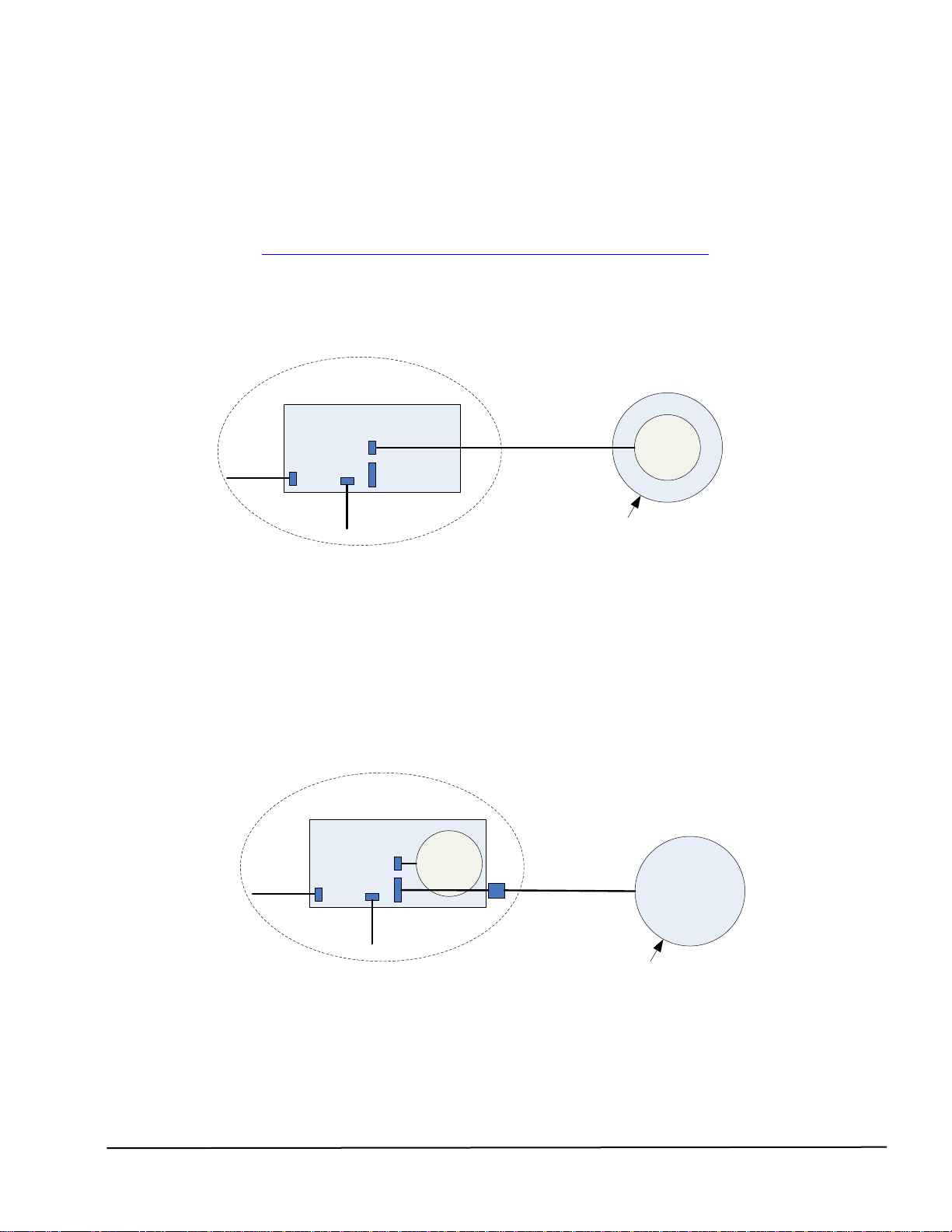
2. System Overview .................................................................................................................7
2.1 NETOEM.........................................................................................................................................7
2.2 NETAOEM......................................................................................................................................7
3. System Components Description.......................................................................................8
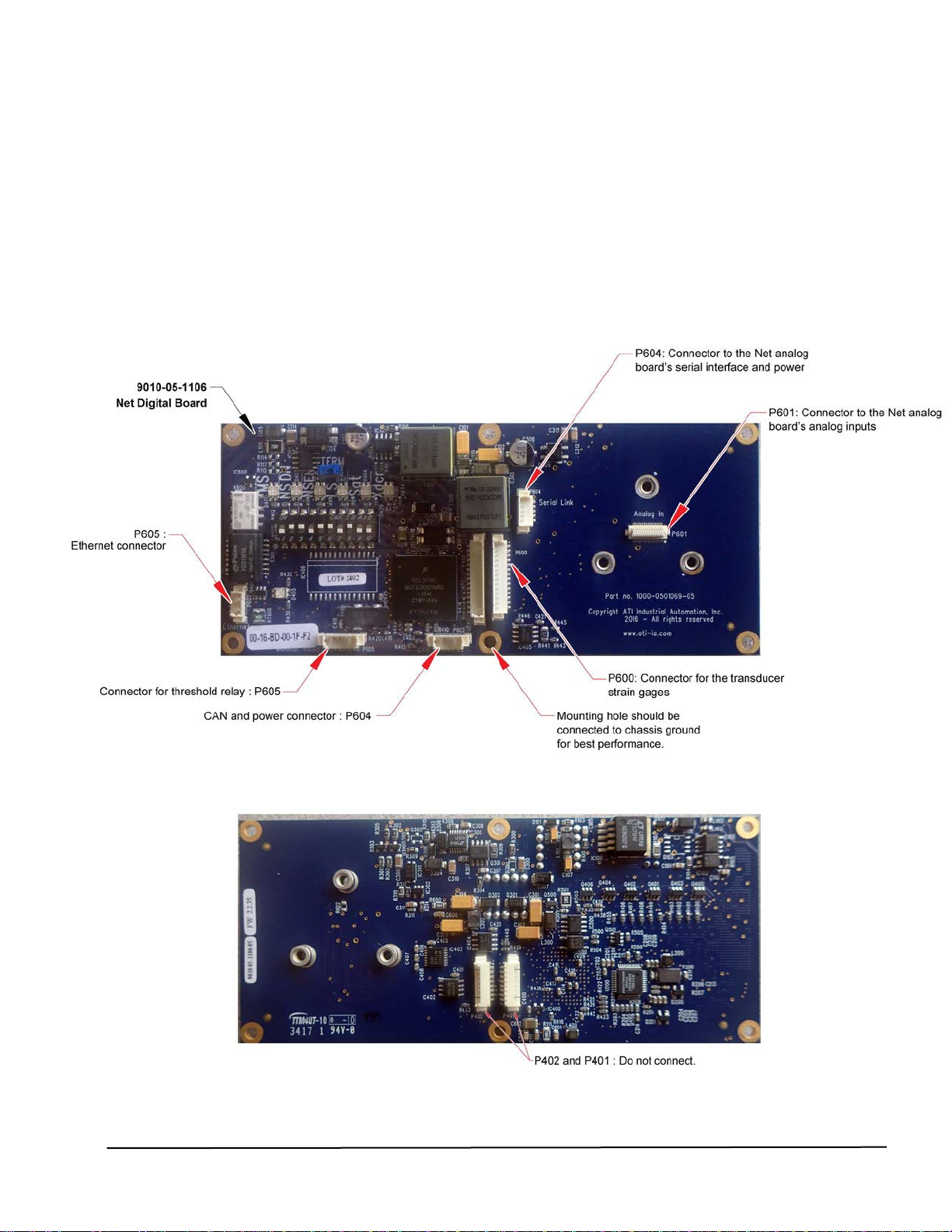
3.1 9010-05-1106 Net Digital Board.....................................................................................................8
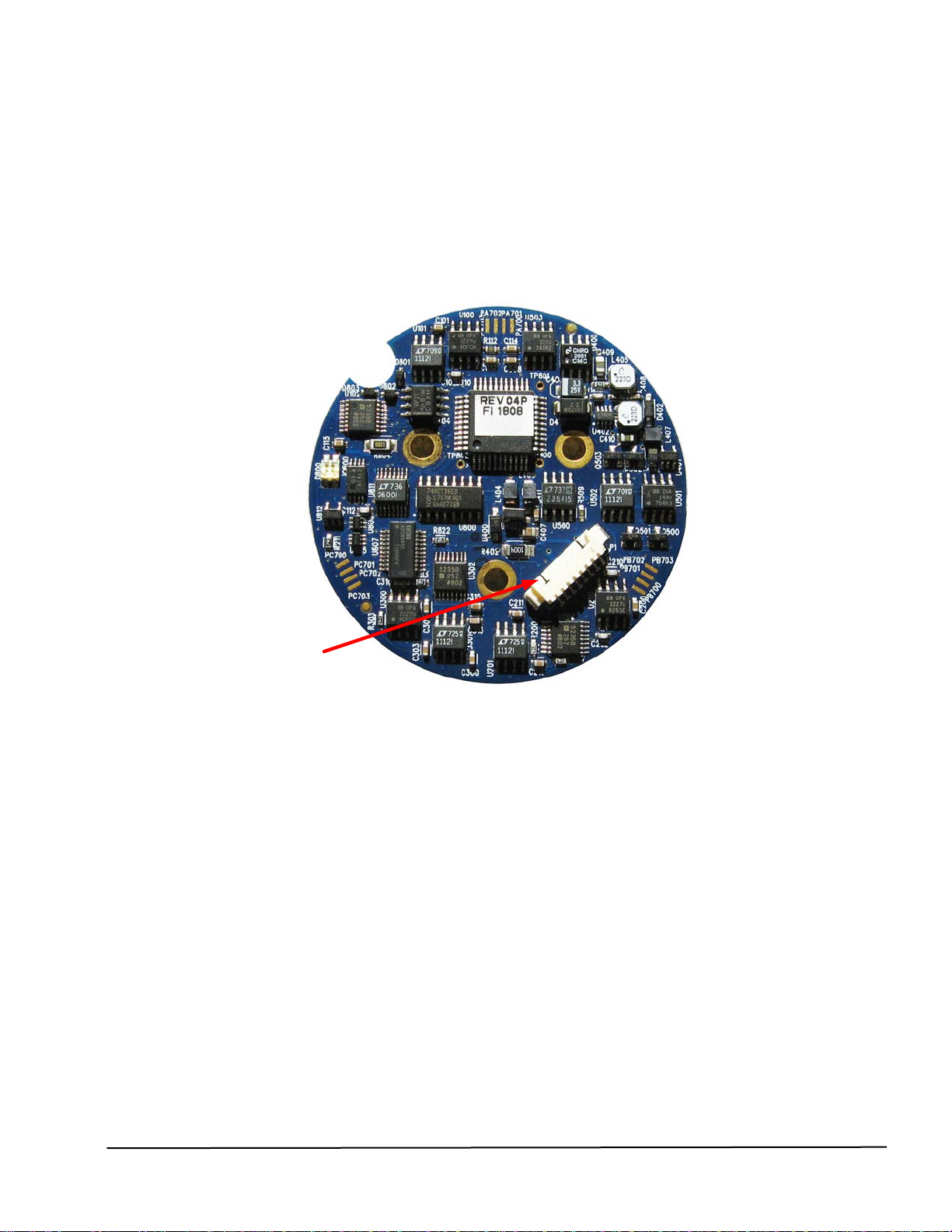
3.2 9010-05-1107 Net Analog Board....................................................................................................9
4. Connectors.........................................................................................................................11
4.1 Net Digital Board connections ......................................................................................................11
4.1.1 P600 Transducer Strain Gage Connector......................................................................11
4.1.2 P602 Ethernet Connector...............................................................................................11
4.1.3 P603 CAN and DC Power Supply Input Connector .......................................................12
4.1.4 P604 Transducer Serial Interface Connector.................................................................12
4.1.5P605 Threshold Relay Connector ..................................................................................12
4.2 Net Analog Board connections.....................................................................................................13
4.2.1 P1 Serial Interface and Power Connector......................................................................13
5. Optional Wire Harnesses...................................................................................................14
5.1 9700-0500005-04 NETAOEM Transducer Strain Gage Wire Harness........................................14
5.2 9000-05-1050 M12-4 Type D Ethernet Wire Harness..................................................................14
5.3 9000-05-1051 M12 Power/CAN Wire Harness.............................................................................15
5.4 9000-05-1052 NETOEM Transducer Wire Harness.....................................................................16
5.5 9000-05-1053 Threshold Relay Wire Harness.............................................................................17
6. Specifications.....................................................................................................................18
6.1 Storage and Operating Conditions ...............................................................................................18
6.1.1 Temperature ...................................................................................................................18
6.2 Electrical Specifications................................................................................................................18
6.2.1 Power Supply..................................................................................................................18
6.2.2 Threshold Relay..............................................................................................................18
6.3 Weights and Dimensions..............................................................................................................18
7. Drawings.............................................................................................................................19
7.1 9230-05-1372 Net Digital and Analog Board Drawing .................................................................19
8. Terms and Conditions of Sale...........................................................................................20