ATI Technologies Speedeburr 9150-AC-90 User manual

Engineered Products for Robotic Productivity
Pinnacle Park • 1031 Goodworth Drive •Apex, NC 27539 USA• Tel: +1.919.772.0115 • Fax: +1.919.772.8259 • www.ati‑ia.com • Email: info@ati‑ia.com
ATI Axially Compliant
Robotic Deburring Tools
Speedeburr™
(Models 9150‑AC‑90 and 9150‑AC‑180)
Product Manual
Document #: 9610-50-1029

Manual, Speedeburr, AC‑90 and 180 Series
Document #9610‑50‑1029‑02
Pinnacle Park • 1031 Goodworth Drive •Apex, NC 27539 USA• Tel: +1.919.772.0115 • Fax: +1.919.772.8259 • www.ati‑ia.com • Email: info@ati‑ia.com
2
Foreword
CAUTION: This manual describes the function, application, and safety considerations of this
product. This manual must be read and understood before any attempt is made to install or
operate the product, otherwise damage to the product or unsafe conditions may occur.
Information contained in this document is the property of ATI IndustrialAutomation, Inc. (ATI) and shall not be
reproduced in whole or in part without prior written approval of ATI. The information herein is subject to change without
notice. This manual is periodically revised to reect and incorporate changes made to the product.
The information contained herein is condential and reserved exclusively for the customers and authorized agents of ATI
Industrial Automation and may not be divulged to any third party without prior written consent from ATI. No warranty
including implied warranties is made with regard to accuracy of this document or tness of this device for a particular
application. ATI Industrial Automation shall not be liable for any errors contained in this document or for any incidental
or consequential damages caused thereby.ATI Industrial Automation also reserves the right to make changes to this
manual at any time without prior notice.
ATI assumes no responsibility for any errors or omissions in this document. Users’ critical evaluation of this document is
welcomed.
Copyright by ATI Industrial Automation. All rights reserved.
How to Reach Us
Sale, Service and Information about ATI products:
ATI Industrial Automation
1031 Goodworth Drive
Apex, NC 27539 USA
www.ati‑ia.com
Tel: +1.919.772.0115
Fax: +1.919.772.8259
E‑mail: info@ati‑ia.com
Technical support and questions:
Application Engineering
Tel: +1.919.772.0115, Option 2, Option 2
Fax: +1.919.772.8259
E‑mail: mech_support@ati‑ia.com

Manual, Speedeburr, AC‑90 and AC‑180 Series
Document #9610‑50‑1029‑02
Pinnacle Park • 1031 Goodworth Drive •Apex, NC 27539 USA• Tel: +1.919.772.0115 • Fax: +1.919.772.8259 • www.ati‑ia.com • Email: info@ati‑ia.com
3
Table of Contents
Foreword.......................................................................................................................................... 2
Glossary........................................................................................................................................... 5
1. Safety......................................................................................................................................... 6
1.1 ExplanationofNotications.........................................................................................................6
1.2 General Safety Guidelines............................................................................................................6
1.3 Safety Precautions........................................................................................................................6
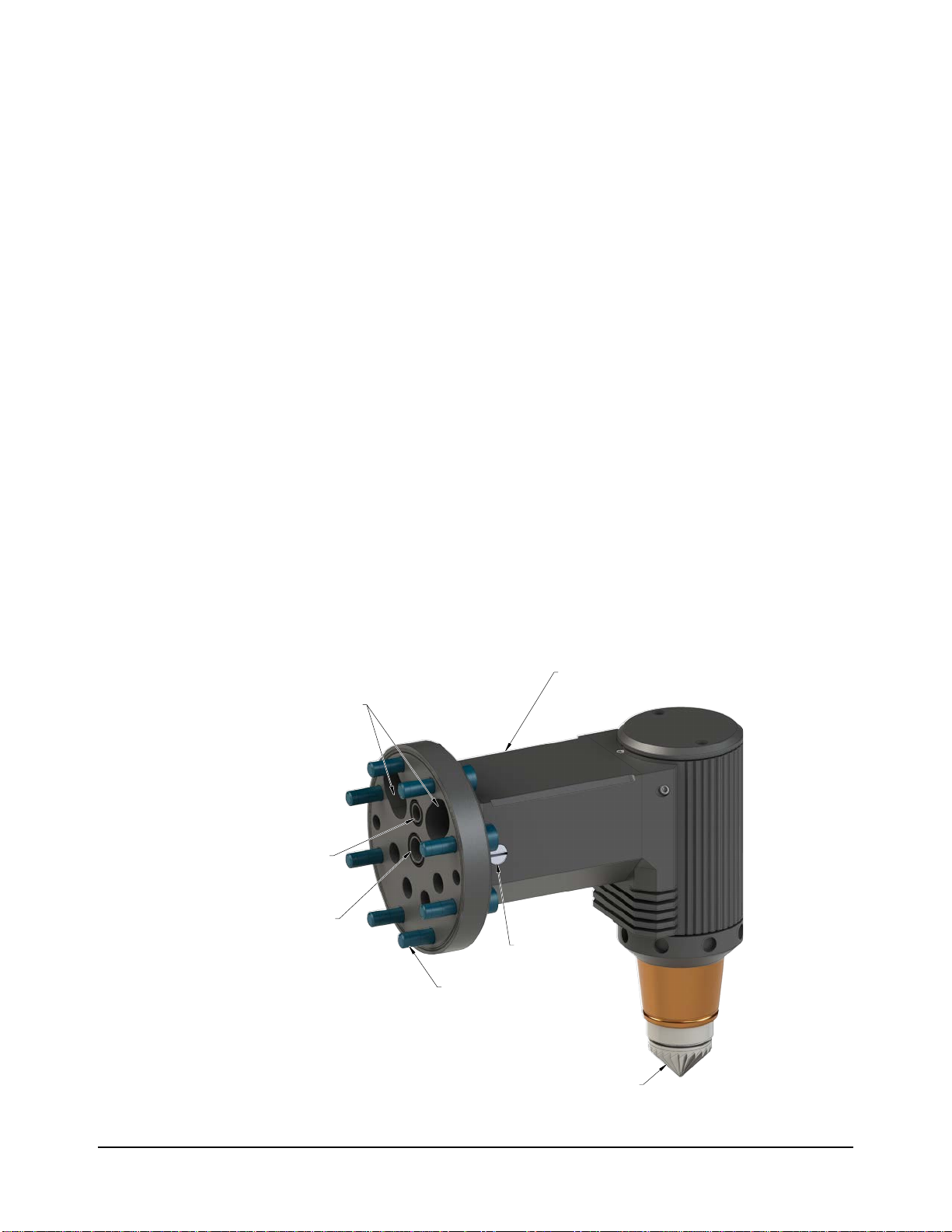
2. Product Overview..................................................................................................................... 7
2.1 FFP..................................................................................................................................................8
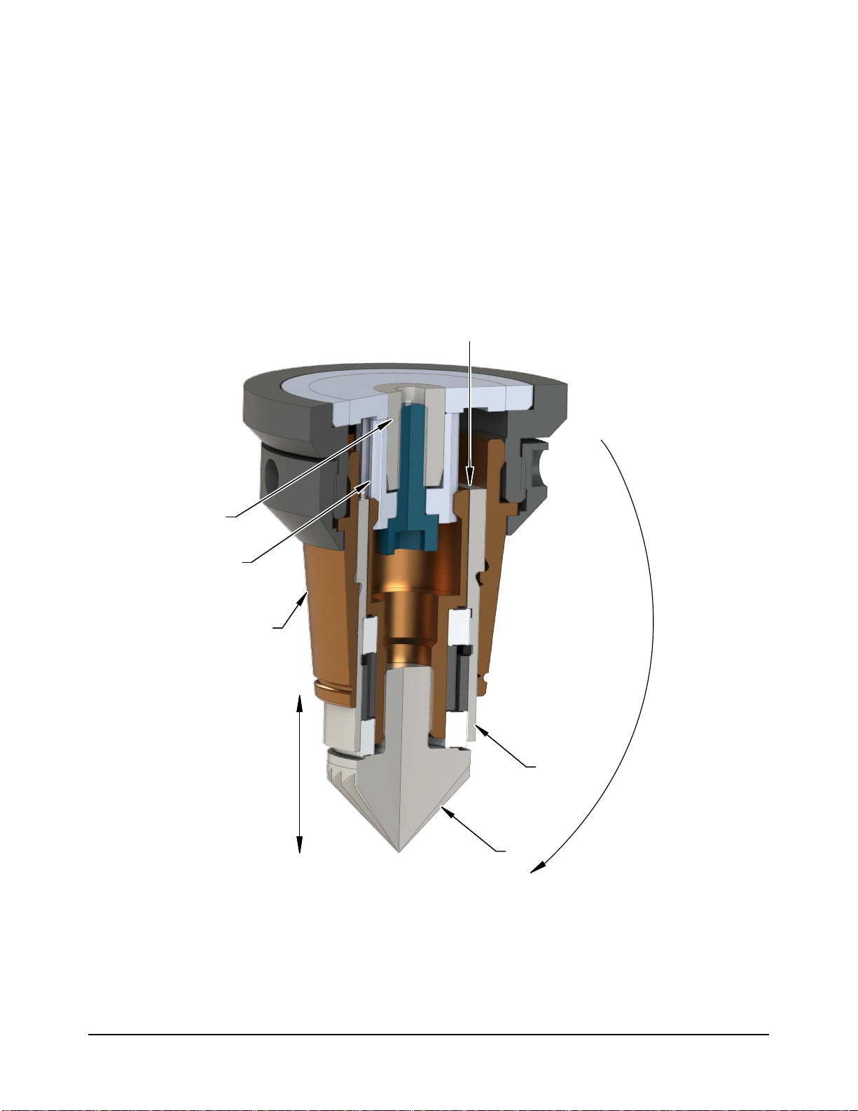
2.2 Technical Description ...................................................................................................................9
2.2.1 Environmental Limitations..................................................................................................9
2.2.1.1 Operation............................................................................................................9
2.2.1.2 Storage...............................................................................................................9
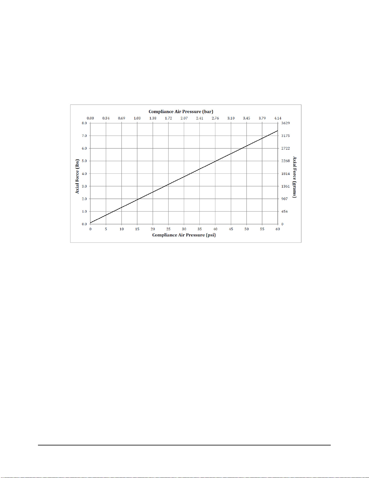
2.2.2 Axial Force/ Compliance Unit Performance .....................................................................10
2.2.3 Air Motor Performance..................................................................................................... 11
3. Installation .............................................................................................................................. 12
3.1 Protection During Transportation..............................................................................................12
3.2 Inspection of Condition When Delivered..................................................................................12
3.3 Unpacking and Handling............................................................................................................12
3.4 Storage and Preventive Maintenance During Storage.............................................................12
3.5 Mounting Installation..................................................................................................................13
3.6 Pneumatics..................................................................................................................................14
4. Operation ................................................................................................................................ 16
4.1 Safety Precautions......................................................................................................................16
4.2 Normal Operation........................................................................................................................17
4.2.1 Air Quality.........................................................................................................................17
4.2.2 Lubrication........................................................................................................................17
4.2.3 Media Selection, Design, and Maintenance.....................................................................17
4.2.4 Deburring Tool Approach Path Should Be Slow and At an Angle.....................................17
4.2.5 No Radial Loading............................................................................................................17
4.2.6 Program the Robot to Incorporate 50% Compliance Travel of the Tool ...........................17
4.3 Speedeburr Working Environment............................................................................................18
4.4 Tool Center Point (TCP) Position...............................................................................................18
4.5 Programming the Deburring Tool Path .....................................................................................18
4.6 Cutter Operation and Burr Selection.........................................................................................19
4.6.1 Bur Selection....................................................................................................................19

Manual, Speedeburr, AC‑90 and 180 Series
Document #9610‑50‑1029‑02
Pinnacle Park • 1031 Goodworth Drive •Apex, NC 27539 USA• Tel: +1.919.772.0115 • Fax: +1.919.772.8259 • www.ati‑ia.com • Email: info@ati‑ia.com
4
5. Maintenance............................................................................................................................ 21
5.1 Pneumatics..................................................................................................................................21
5.2 Lubrication...................................................................................................................................21
5.3 Bur, FFP, Cylinder, Spline, and Lock Ring Inspection .............................................................21
5.4 Overhaul.......................................................................................................................................21
6. Troubleshooting and Service Procedures........................................................................... 22
6.1 Troubleshooting..........................................................................................................................22
6.2 Service Procedures.....................................................................................................................23
6.2.1 Cleaning, Inspection, and Replacement of the Spline, Cylinder, and Lock Ring..............23
6.2.2 Bur and FFP Replacement...............................................................................................25
6.2.3 O‑Ring Replacement for the Air Supply Ports and Tool Flange .......................................27
7. Serviceable Parts ................................................................................................................... 28
7.1 Accessories.................................................................................................................................28
8. Specications ......................................................................................................................... 29
9. Drawings ................................................................................................................................. 30
9.1 AC-90 Speedeburr Customer Drawing......................................................................................30
9.2 AC-180 Speedeburr Customer Drawing....................................................................................33
9.3 Pneumatic Diagrams for AC Tools.............................................................................................36
10. Terms and Conditions of Sale............................................................................................... 38
10.1 Motor Life and Service Interval Statement................................................................................39
10.1.1 Vane Motor Products........................................................................................................39

Manual, Speedeburr, AC‑90 and AC‑180 Series
Document #9610‑50‑1029‑02
Pinnacle Park • 1031 Goodworth Drive •Apex, NC 27539 USA• Tel: +1.919.772.0115 • Fax: +1.919.772.8259 • www.ati‑ia.com • Email: info@ati‑ia.com
5
Glossary
Term Denition
AC Axially compliant.
Adapter Plate Device for attaching the deburring tool to either a robot ange or a stationary
mounting surface.
Air Filter Device for removing contamination from air supply lines. Typically refers to
removal of particulates.
Bur Cutting tool used to remove burrs from the workpiece. Alternatively referred to
as a rotary le, cutter, or bit.
Burr Any unwanted, raised protrusion on the workpiece.
Chattering Machine vibrations. The cutting tool bounces as it contact the work surface.
Coalescing Filter Device designed to remove liquid aerosols from the supply air lines.
Collet Gripping device used to hold cutting tools in the spindle.
Compliance The ability of the spindle to passively move in response to protrusions on or
deviations of the workpiece.
Deburr To remove the burrs from a piece of machined work.
End‑Eector Tool used by the robot to perform a particular function.
FFP Free ying piston. An assembly that moves within the cylinder and spline in the
deburring tool. The FFP attaches to the bur.
ISO
A series of standards that are developed and published by the International
Organization for Standardization (ISO). The standards dene, establish, and
maintain an eective quality assurance system for manufacturing and service
industries.
Positive Displacement A device that captures uid of air and discharges that uid or air at a xed rate.
Positive Stop The tool has contacted a physical limitation and can no longer move.
Regulator Device used to set and control the supplied air pressure to lower acceptable
levels.
Solenoid Valve Electrically controlled device for switching air supplies on and o.
Speedeburr An ATI series of deburring tools that use a vane‑type motor and a oating
rotary cutting bur for edge‑deburring and chamfering of parts.
Vane‑Type A positive displacement air motor design utilizing partitions (vanes) to separate
expansion regions inside a housing.
VG Viscosity Grade.

Manual, Speedeburr, AC‑90 and 180 Series
Document #9610‑50‑1029‑02
Pinnacle Park • 1031 Goodworth Drive •Apex, NC 27539 USA• Tel: +1.919.772.0115 • Fax: +1.919.772.8259 • www.ati‑ia.com • Email: info@ati‑ia.com
6
1. Safety
The safety section describes general safety guidelines to be followed with this product, explanations of the
notications found in this manual, and safety precautions that apply to the product. More specic notications are
imbedded within the sections of the manual where they apply.
1.1 ExplanationofNotications
The following notications are specic to the product(s) covered by this manual. It is expected that the user
heed all notications from the robot manufacturer and/or the manufacturers of other components used in the
installation.
DANGER: Notication of information or instructions that if not followed will result in
death or serious injury. The notication provides information about the nature of the
hazardous situation, the consequences of not avoiding the hazard, and the method for
avoiding the situation.
WARNING: Notication of information or instructions that if not followed could result
in death or serious injury. The notication provides information about the nature of the
hazardous situation, the consequences of not avoiding the hazard, and the method for
avoiding the situation.
CAUTION: Notication of information or instructions that if not followed could result
in moderate injury or will cause damage to equipment. The notication provides
information about the nature of the hazardous situation, the consequences of not
avoiding the hazard, and the method for avoiding the situation.
NOTICE: Notication of specic information or instructions about maintaining, operating,
installing, or setting up the product that if not followed could result in damage to equipment. The
notication can emphasize, but is not limited to: specic grease types, best operating practices,
and maintenance tips.
1.2 General Safety Guidelines
Prior to purchase, installation, and operation of the Speedeburr product, the customer should rst read and
understand the operating procedures and information described in this manual. Never use the deburring tool
for any purposes, or in any ways, not explicitly described in this manual. Follow installation instructions and
pneumatic connections as described in this manual.
All pneumatic ttings and tubing must be capable of withstanding the repetitive motions of the application
without failing. The routing of pneumatic lines must minimize the possibility of stress/strain, kinking,
rupture, etc. Failure of critical pneumatic lines to function properly may result in equipment damage.
1.3 Safety Precautions
CAUTION: Do not use spare parts other than ATI spare parts. Use of spare parts not
supplied by ATI can damage equipment and void the warranty.Always use genuine ATI
spare parts.
CAUTION: Do not perform maintenance or repair on the Speedeburr product unless
the tool is safely supported or placed in the tool stand and air has been turned
o. Injury or equipment damage can occur with tool not placed in a tool stand and
air remaining on. Place the tool safely in the tool stand and turn o the air before
performing maintenance or repair on the Speedeburr product.

Manual, Speedeburr, AC‑90 and AC‑180 Series
Document #9610‑50‑1029‑02
Pinnacle Park • 1031 Goodworth Drive •Apex, NC 27539 USA• Tel: +1.919.772.0115 • Fax: +1.919.772.8259 • www.ati‑ia.com • Email: info@ati‑ia.com
7
2. Product Overview
The AC deburring tool, which is also known as Speedeburr, is a robust, high‑speed, and lightweight vane‑type
air motor deburring unit with a oating rotary cutting bur for edge‑deburring and chamfering of materials such as
aluminum, plastic, and steel.
The AC deburring tool’s pneumatically controlled, articulated design allows the bur to follow the part prole and
compensate for surface irregularities while maintaining a constant force. This axial force/compliance air supply
system provides increased stiness in the path direction and decreased stiness in the contact force direction, both
of which prevent the tool from chattering.
The AC deburring tool utilizes a rotary cutting bur of tungsten carbide or coated with PCD or CBN. Because the
rotary bur has a 45° cutting angle, compliance is lateral and axial.
Custom adapter plates for mounting to the robot, work bench, or a tool xture are available from ATI. Refer to
Section 9—Drawings for more information.
The AC deburring tools have the following pneumatic ports:
• (1) port for axial force/compliance supply that provides constant force on the bur.
• (1) port for motor air supply.
• (2) port(s) for motor exhaust.
ATI has (2) models of the AC deburring tool: 9150‑AC‑90 and 9150‑AC‑180. Both models are similar except for
the following features:
• On the AC‑90, the motor housing extends perpendicular, at a 90° angle, from the mounting bracket. On the
AC‑180, the motor housing extends linearly, 180°, with the mounting bracket. Refer to Section 9—Drawings.
• On the side of the 90° angled bracket, the AC‑90 has an adjustment screw with which the user can use a
small at‑blade screw to adjust the motor speed. The motor speed can also be adjusted on both models by
adjusting the motor air supply pressure. Refer to Section 4.5—Programming the Deburring Tool Path for
more information.
Figure 2.1—AC Deburring Tool (9150-AC-90 Shown)
(2) Motor Exhaust Port
(1) Compliance/
Axial Pressure Air Port
(1) Motor Air
Supply Port
(8) M4 Socket Head
Cap Screw
Adjustment Screw
Bur
AC Deburring Tool

Manual, Speedeburr, AC‑90 and 180 Series
Document #9610‑50‑1029‑02
Pinnacle Park • 1031 Goodworth Drive •Apex, NC 27539 USA• Tel: +1.919.772.0115 • Fax: +1.919.772.8259 • www.ati‑ia.com • Email: info@ati‑ia.com
8
2.1 FFP
The FFP is an important component of the AC deburring tool.
A remotely controlled axial force/compliance air pressure pushes the FFP forward into contact with the bur
edge.
Then the air vane motor uncouples from the linear movement of the FFP to reduce inertia and increase the
stability of the contact force during deburring.
Then the spline coupling transmits torque to the bur. Ball bearings within the motor compartment of the tool
ensure the bur operates evenly.
A small amount of frictional torque is transmitted through the ball bearings to the FFP cylinder that rotates
slowly inside the stationary outer cylinder. This small frictional torque prevents stick‑slip or static friction of
the FFP. The FFP cylindrical body is precision grounded to minimize friction in the axial direction.
Figure 2.2—FFP (AC-180 Shown)
8 mm
(0.315”)
Bur
Cylinder
FFP
Axial Stroke
Spline
Air Vane Motor
Axial Force/
Compliance
Pressure

Manual, Speedeburr, AC‑90 and AC‑180 Series
Document #9610‑50‑1029‑02
Pinnacle Park • 1031 Goodworth Drive •Apex, NC 27539 USA• Tel: +1.919.772.0115 • Fax: +1.919.772.8259 • www.ati‑ia.com • Email: info@ati‑ia.com
9
2.2 Technical Description
A technical overview of the product is provided in the following tables and graph. For additional technical
specications, refer to Section8—Specications.
2.2.1 Environmental Limitations
2.2.1.1 Operation
Table 2.1—Operation
Installation
Position
Mounted to robot.
Mounted to a table or stand by means of the bench
adapter. The robot is carrying the work piece to the
deburring tool.
Temperature
Range 5 °C – 35 °C
41 °F – 95 °F
Utilities
The tool requires the following:
• Clean, dry, ltered, and lubricated air.
• A coalescing lter and lter elements that are rated
5 micron or better.
• Air supply to the spindle must be 6.2 bar (90 psi) to
develop the full rated power.
• The axial force/compliance air must be supplied at
1.0–4.1 bar (15–60 psi) from a regulated source.
2.2.1.2 Storage
Table 2.2—Storage
Temperature
Range 0 °C – 45 °C
32 °F – 113 °F
Conditions
The tool should be stored in its crate and in a dry
place.
When not in use, keep the unit in its crate if possible.
Consult Section 3.4—Storage and Preventive
Maintenance During Storage of this manual.

Manual, Speedeburr, AC‑90 and 180 Series
Document #9610‑50‑1029‑02
Pinnacle Park • 1031 Goodworth Drive •Apex, NC 27539 USA• Tel: +1.919.772.0115 • Fax: +1.919.772.8259 • www.ati‑ia.com • Email: info@ati‑ia.com
10
2.2.2 Axial Force/ Compliance Unit Performance
The following graph illustrates the variation of compliance force with applied axial force/
compliance air pressure. Measurements may vary from one product to another and should only be
treated as nominal.
Axial force/compliance is also dependent upon the material of the work piece, type of bur tool, and
the amount of material that is removed.
Figure 2.3—AC Axial Contact Force (measured with the rotary bur pointing down)

Manual, Speedeburr, AC‑90 and AC‑180 Series
Document #9610‑50‑1029‑02
Pinnacle Park • 1031 Goodworth Drive •Apex, NC 27539 USA• Tel: +1.919.772.0115 • Fax: +1.919.772.8259 • www.ati‑ia.com • Email: info@ati‑ia.com
11
2.2.3 Air Motor Performance
The following graphs illustrate the motor torque and power performance. The air motor operating
speed changes according to the applied load, until the motor develops the power that is required
to perform the specic task. The idle speed of the motor is at maximum, when no load is applied.
Without an applied load, the motor decreases to a slower operating speed at which the motor
develops maximum torque. ATI recommends a working speed of 15,000 to 25,000 RPM for
maximum possible output. The operating speed that is less than 15,000 RPM risks the motor
stalling because of the higher torque at lower speeds.
Figure 2.4—AC Output Torque and Power

Manual, Speedeburr, AC‑90 and 180 Series
Document #9610‑50‑1029‑02
Pinnacle Park • 1031 Goodworth Drive •Apex, NC 27539 USA• Tel: +1.919.772.0115 • Fax: +1.919.772.8259 • www.ati‑ia.com • Email: info@ati‑ia.com
12
3. Installation
The deburring tool is delivered fully assembled. Optional equipment such as mounting adapter plates and bur tools
are separate.
3.1 Protection During Transportation
The deburring tool arrives in packaging that secures and protects the tool during transportation. Always use
this packaging when storing or transporting the deburring tool in order to minimize the risk of damage.
3.2 Inspection of Condition When Delivered
Upon receipt, the following should be checked:
• Delivery in accordance with freight documents.
• Packaging is in good condition.
If there is damage to any of the packaging, or if any of the goods have been exposed to abnormal handling,
unpack those parts that may have been damaged for a closer inspection. If necessary, notify ATI for
assistance in the evaluation of the product condition.
3.3 Unpacking and Handling
The deburring tool should always be placed inside the accompanying packaging, while transporting, storing,
and handling.
Pneumatic lines and cables should be attached, bundled, and strain‑relieved in a manner that allows for
freedom of movement during operation.
3.4 Storage and Preventive Maintenance During Storage
The deburring tool should always be stored in its accompanying packaging, when not in use. The deburring
tool should be stored in a dry place.
For long‑term storage, the deburring tool should be thoroughly cleaned of any burrs or debris. Do not
disassemble the deburring tool. After cleaning, ll the deburring tool with oil of the same type that was used
as a lubrication during operation. Lubrication is necessary to keep the blades in the air‑vane motor from
drying out and prevent corrosion. Place the deburring tool inside a sealed plastic bag. Place the bag with its
contents inside the crate.

Manual, Speedeburr, AC‑90 and AC‑180 Series
Document #9610‑50‑1029‑02
Pinnacle Park • 1031 Goodworth Drive •Apex, NC 27539 USA• Tel: +1.919.772.0115 • Fax: +1.919.772.8259 • www.ati‑ia.com • Email: info@ati‑ia.com
13
3.5 Mounting Installation
CAUTION: Thread locker applied to fasteners must not be used more than once.
Fasteners might become loose and cause equipment damage. Always apply new
thread locker when reusing fasteners.
The mounting pattern of the AC deburring tool consists of (8) M4 through holes. Refer to the following
gure and Section 9—Drawings. An optional adapter plate allows the deburring tool to attach to a robot
arm, other work surface, or an intermediate adapter plate. Verify the O‑rings are positioned correctly into the
grooves on the deburring tool bracket before mounting the tool to the adapter plate. If the AC deburring tool
is permanently mounted to a work surface, the robot carries the part to be deburred to the deburring tool.
Figure 3.1—Mounting Installation (9150-H/T-3178 Adapter Shown.)
(9150-H/T-3179 is the same but with G (BSPP) ports and a M5 compliance air port.)
AC Deburring Tool
Adapter Plate
(9150-H/T-3178 Shown)
(2) 1/4 NPT
Motor Exhaust
(1) 1/8 NPT
Motor Air Supply Port
(1) 10-32
Axial Force/Compliance Air Supply Port
(8) M4 Socket Head
Cap Screw
(2) O-ring
Mounting Bracket
(4) M6 Socket Head
Cap Screw
(Customer Supplied)
Dowel Pin
(Customer Supplied)

Manual, Speedeburr, AC‑90 and 180 Series
Document #9610‑50‑1029‑02
Pinnacle Park • 1031 Goodworth Drive •Apex, NC 27539 USA• Tel: +1.919.772.0115 • Fax: +1.919.772.8259 • www.ati‑ia.com • Email: info@ati‑ia.com
14
3.6 Pneumatics
Conventional, customer‑supplied, pneumatic components are used to control the air supply to the deburring
tool. Consult the valve and regulator supplier’s literature when selecting these components.
Section 9.3—Pneumatic Diagrams for AC Tools shows the (2) connection options for the motor and axial
(compliance) force air supplies:
• Option 1: (1) solenoid valve to control both the motor drive air supply and axial force air supply.
• Option 2: (1) solenoid valve to control the motor air supply and another solenoid valve to control axial
force air supply.
A robot controller actuates the solenoid valves by issuing a digital output signal.
CAUTION: No lubrication causes damage to the motor within a short period of time. If
the motor is not properly lubricated, the motor operates audibly slower than normal and
the speed varies. Ensure the deburring tool is properly lubricated. Install the lubrication
equipment near the robot base and a maximum of (16) feet away from the deburring
tool. Refer to Section 4.2.2—Lubrication for more information.
CAUTION: When the system is rst installed, use a higher oil setting that is
approximately twice the recommended setting. Stay at this setting, until the unit is
receiving consistently oiled air. Run the oil through the entire pneumatic tube between
the oiler and the unit before normal operation.
CAUTION: It is recommended that the customer use a coalescing lter and lter
elements rated 5 micron or better.
ATI recommends that the user install a pneumatic pressure regulator (ATI Part #9150‑FFR‑90, or equivalent)
to achieve a stable air supply of 6.2 bar (90 psi) to the motor. Refer to Section8—Specications for the
maximum ow requirements. Because the deburring motor is a positive displacement device, lower
operating speeds can be achieved by reducing the motor supply air pressure.
Ensure the air lubrication system is lled with oil. Refer to Section 4.2.2—Lubrication for more information.
Use a coalescing lter with elements that are rated for 5 micron or better. An oil recovery unit may be
installed on the exhaust line to avoid the mist lubrication droplets from entering the atmosphere around the
robot installation.
Use a second, precision, self‑relieving regulator (ATI Part # 9150‑P16‑B‑6, or equivalent) for the axial
force/compliance mechanism. Compliance corresponds to the axially applied force on the rotary bur. The
axial force/compliance air supply must be lubricated. Because very little airow is required, a smaller valve
can be used.
If the complete work piece can be deburred with equal force, a conventional, manual pressure regulator can
be used for the axial force/compliance air supply. If the burrs, which are to be removed, vary from place
to place on the work piece, and this variation is repeatable for all work pieces of the same type, it may be
necessary to adjust the force using an analog pressure regulator that is controlled from the robot. An analog
output port in the robot or logic controller will be needed.
The axial force/compliance air supply pressure regulator should have a 1.0‑4.1 bar (15‑60 psi) range. When
testing for the proper contact force, start with a very low pressure and increase slowly until the desired
chamfer is achieved. Typically start at 3 psi (0.21 bar) for aluminum and at a higher pressure for steel
workpieces.

Manual, Speedeburr, AC‑90 and AC‑180 Series
Document #9610‑50‑1029‑02
Pinnacle Park • 1031 Goodworth Drive •Apex, NC 27539 USA• Tel: +1.919.772.0115 • Fax: +1.919.772.8259 • www.ati‑ia.com • Email: info@ati‑ia.com
15
WARNING: All pneumatic ttings and tubing must be capable of withstanding the
repetitive motions of the application without failing. The routing of pneumatic lines must
minimize the possibility of over stressing, pullout, or kinking the lines. Failure to do
so can cause some critical pneumatic lines not to function properly and may result in
damage to the equipment.
Table 3.1—Pneumatic Connections
Connection
Function
Connection Type Pressure Requirement
Adapter
P/N 9150-H/T-3178 Adapter
P/N 9150-H/T-3179
Motor Air Supply 1/8 NPT G 1/8 (BSPP) 90 psi (6.2 bar)
Axial Force/
Compliance Air
Supply 10‑32 M5 1.0–4.1 bar
(15–60 psi)
Exhaust Vented to the
atmosphere through
(2) 1/4 NPT ports
Vented to the
atmosphere through
(2) G 1/8 (BSPP)
ports
Not Applicable
For the motor air supply, use the largest possible exible plastic tubing or hose that has a 10 mm (3/8”)
minimum inside diameter. For the axial force/compliance air supply, 4 mm (5/32”) outer diameter plastic
tubing is sucient.
To keep the sound level to a minimum mount (2) silencers on the (2) exhaust outlets or route exhaust to
a remote outlet location or oil recovery device. Use a minimum of 13 mm (1/2") diameter plastic tubing.
Always use the largest size exhaust tubing possible with the minimum required length to limit backpressure.
Refer to Section8—Specications for information about the sound level of the deburring tool. The sound
level around deburring equipment cannot be predicted by ATI, because the sound pressure from deburring
operations is process and part dependent. To reduce the sound from the cutting operation in nearby working
areas, a customer‑supplied barrier surrounding the installation may be installed (Plexiglas® or Lexan®is
preferred).

Manual, Speedeburr, AC‑90 and 180 Series
Document #9610‑50‑1029‑02
Pinnacle Park • 1031 Goodworth Drive •Apex, NC 27539 USA• Tel: +1.919.772.0115 • Fax: +1.919.772.8259 • www.ati‑ia.com • Email: info@ati‑ia.com
16
4. Operation
These operating instructions are intended to help system integrators program, start up, and complete a robotic
deburring cell containing a deburring tool. The system integrator should be familiar with the task of deburring and
have extensive knowledge about automation applications that incorporate robots.
4.1 Safety Precautions
DANGER: NEVER use the Speedeburr for purposes other than robotic deburring. If
used in any other way, serious injury or damage to equipment may occur.
DANGER: NEVER use the Speedeburr as a hand‑held machine. If used in this way,
serious injury or damage to equipment will occur.
WARNING: All personnel, who are involved in the operation of the deburring tool,
should have a thorough understanding of the operating procedures. Failure to follow
these procedures or neglecting safety precautions can create hazardous situations that
may injure personnel or damage the deburring installation and the deburring tool.
WARNING: Never operate the Speedeburr product without wearing hearing protection.
High sound levels can occur during cutting. Failure to wear hearing protection can
cause hearing impairment. Always use hearing protection while working in proximity of
the deburring tool.
WARNING: Never operate the Speedeburr product without wearing eye protection.
Flying debris can cause injury. Always use eye protection while working in the
neighborhood of the deburring tool.
CAUTION: Only use burs that are supplied by ATI. Using a bur, which is from another
distributer, is not properly designed for the ATI deburring tool and may cause injury or
damage equipment.
CAUTION: Failure to properly handle the lubrication material and long‑time exposure
to air that contains oil could cause injury to personnel. Refer to the lubrication safety
data sheet (SDS) for more information about the material properties, proper handling/
storage/disposal practices, and what to do in the event of an accidental exposure.
CAUTION: Never be present near the deburring tool while it is started or in operation.
Flying debris and rotating parts can cause injury. If it is necessary to approach the
deburring tool while in motion, stand behind appropriate Plexiglas®or Lexan®windows.
Provide a barrier to prohibit people from approaching the deburring tool while in
operation.
CAUTION: Never use or start the deburring tool without rst reading and understanding
the operating procedures described in this manual. Never use the deburring tool for any
purposes, or in any ways, not explicitly described in this document. Using the deburing
tool without fully understanding the installation and operating procedures may cause
injury to personnel or damage to equipment. Mount the deburring tool and connect the
pneumatic control equipment as described in this manual. Operate the deburring tool
as described in the manual.
CAUTION: Protect the brass cylinder that encloses the FFP from collisions. If struck,
the cylinder may be damaged and need to be replaced in order to continue normal
operations.

Manual, Speedeburr, AC‑90 and AC‑180 Series
Document #9610‑50‑1029‑02
Pinnacle Park • 1031 Goodworth Drive •Apex, NC 27539 USA• Tel: +1.919.772.0115 • Fax: +1.919.772.8259 • www.ati‑ia.com • Email: info@ati‑ia.com
17
4.2 Normal Operation
The following sections describe the normal operating conditions for the AC deburring tools.
4.2.1 Air Quality
The air supply should be clean, dry, ltered, and lubricated. A coalescing lter that has elements
rated for 5 micron or better is required. The air must be supplied at 6.2 bar (90 psi).
Air quality aects tool performance more than almost any other factor. Particulate can block
airow or impede vane motion. If deburring tools do not receive the proper air pressure, the tool
stalls. Any water in the system damages the housing and blades.
4.2.2 Lubrication
Vane motors for the AC deburring tool must have oil in the motor air supply. Otherwise, the vane
material wears against the housing and degrades quickly. Premature failure results, when using the
deburring tool without lubrication.
Use a brand name air tool oil with a viscosity in the range of IS0 VG 32 to ISO VG 46. For
example, use Mobil™ ALMO OIL 525, which is available from many industrial suppliers.
Do not use oilfog air lubrication systems. Only use microfog systems.
Lubricate the air supply with 3‑4 drops of oil per minute.
The length of the lubrication supply hose between the lubricator and the air motor should be no
more than 5 m (16 feet).
4.2.3 Media Selection, Design, and Maintenance
Use genuine, proprietary ATI carbide burs.
Check media quality regularly to ensure it is not dull or worn. Using worn media causes poor
surface nish and premature tool failure because of increased wear on the bearings.
Under normal conditions, no cooling or lubrication of the bur is necessary.
4.2.4 Deburring Tool Approach Path Should Be Slow and At an Angle
The deburring tool should approach the workpiece slowly and at an angle.
When beginning a deburring pass, try to minimize the initial impact on the work piece by slowly
approaching the tool at an angle while maintaining a slightly parallel path with the surface.
If the tool quickly approaches perpendicularly to the workpiece, the result is gouging and
premature wear of the tool bearings and results in premature failing of the unit. Additionally,
collisions could result and create a hazardous situation for both personnel and equipment.
4.2.5 No Radial Loading
Do not apply radial loads that are perpendicular to the axis of rotation.
Do not use the AC deburring tool to perform grinding, countersinking, or other metal‑forming
processes.
4.2.6 Program the Robot to Incorporate 50% Compliance Travel of the Tool
Program the robot to have the tool's compliance at 50% travel when on the nominal path.
As the part's edge deviates from the perfect path, the cutting bit can use compliance to follow along
high and low spots without losing contact or hitting the positive stop and gouging.
Do not "bottom out" the compliance and hit the positive stop.
Repeated impacts on the positive stop can damage the compliance mechanism or motor.

Manual, Speedeburr, AC‑90 and 180 Series
Document #9610‑50‑1029‑02
Pinnacle Park • 1031 Goodworth Drive •Apex, NC 27539 USA• Tel: +1.919.772.0115 • Fax: +1.919.772.8259 • www.ati‑ia.com • Email: info@ati‑ia.com
18
4.3 Speedeburr Working Environment
As described in previous sections, the AC deburring tool should only be used in conjunction with a robot in
a secured work cell/chamber.
The work cell must be secured by means of barriers to prohibit personnel from entering the cell. A lockable
door should be included as a part of the barrier in order to facilitate access to the cell for authorized
personnel only. The barrier could consist partly or fully of Plexiglas to facilitate observation of the deburring
operations.
During system or deburring tool maintenance, make sure the AC deburring tool and robot are stopped before
entering the robot cell. When installing and testing, never be present in the cell when the deburring tool is
running.
Be aware of rotating parts. Use eye‑protection while working around the deburring tool.
Be aware of high sound levels. Always use hearing protection while working in the proximity of the
deburring cell.
The deburring tool should not be used to deburr materials that are prone to fracture. A fracturing work
piece may result in pieces of material damaging surrounding working environment and personnel. Material
removed correctly should be in the form of chips.
4.4 Tool Center Point (TCP) Position
The overall deburring tool dimensions are shown in Section 9—Drawings. When setting the TCP position
in the robot controller, use the mid‑position of the 8 mm(0.315") axial stroke of the FFP. Also, take into
account the depth of the Speedeburr adapter plate. If an additional interface plate is used to t the adapter to
the robot, this depth must be considered while setting the TCP position.
Table 4.1—Setting the TCP Distance for X, Y, and Z
Conguration Distance for AC-90 Distance for AC-180
X Y Z X Y Z
Without the Speedburr
adapter 74.93 mm
(2.95") 0‑69.85 mm
(‑2.75") N/A
‑114.81 mm
(‑4.52")
With the Speedeburr
adapter 109.98 mm
(4.33") ‑149.86 mm
(‑5.90")
4.5 Programming the Deburring Tool Path
The overall deburring tool dimensions are shown in Section 9—Drawings.
While various methods are available to program the robot path, the bur should be nominally at the mid‑point
of its stroke while deburring a part. The bur moves up and down with part and path variation. The method
that is used depends upon the capabilities of the robot and the programmer's preferences.
One programming method is to use the point of the bur as a guide, follow the edge of the part, and then
manually or automatically add osets to the path points to achieve the correct path.
Another programming method is to input into the robot the actual points that are along the path. If this
method is used, make sure that at each point the bur is at its nominal mid‑point when in contact with the part
and that there are no radial forces.
If an application requires the deburring of sharp inner corners, it may be required to use the area of the bur
that is closer to tip. In this case, compensation and cutting surface speed of the deburring tool are reduced.
When rst running the robot program, observe the path with the axial force/compliance air supply turned
o. When increasing the path speed, notice if the path deviates. Verify that at the operational robot path
speed the bur remains near the mid‑point of its axial travel.
Adjust the axial force/compliance air supply as described in Section 3.6—Pneumatics to achieve the correct
sized and even chamfer.

Manual, Speedeburr, AC‑90 and AC‑180 Series
Document #9610‑50‑1029‑02
Pinnacle Park • 1031 Goodworth Drive •Apex, NC 27539 USA• Tel: +1.919.772.0115 • Fax: +1.919.772.8259 • www.ati‑ia.com • Email: info@ati‑ia.com
19
To change the motor speed, adjust the main supply pressure, for example: increasing the pressure, increases
the speed. On the AC‑90, the user can adjust the speed by using a small at‑blade screwdriver to turn the
adjustment screw on the side of the 90° bracket (refer to Figure 2.1). This adjustment varies the ow rate,
for example: clockwise to decrease and counter‑clockwise to increase the ow rate and speed. In most
applications, it is best to adjust the regulator to a maximum pressure 6.2 bar (90 psi) with the adjustment
screw in the full out position, which is approximately ush with the surface.
4.6 Cutter Operation and Burr Selection
To obtain optimal results, the FFP should operate with little friction in the cylinder. Refer to Section 5—
Maintenance for more information.
The deburring tool should not be operated for extensive periods of time with the cutting tip pointing up.
This orientation increases the amount of debris that enters the cylinder and causes premature damage to the
cylinder and FFP. If the deburring tool must be operated in this orientation, then a continuous or regular
burst of high velocity air should be used to blow debris away from the FFP and cylinder to ensure minimal
friction between the components.
The selection of a cutting tool is highly dependent upon the part material and geometry, and the depth of cut.
Please see Section 4.6.1—Bur Selection for a bur and suitable applications.
4.6.1 Bur Selection
ATI can provide guidance in bur selection; however, only experimentation yields the results
desired. The following table may assist in bur selection.
Table 4.2—Bur Selection
Description Application
9150-HIAC-4579-C2
• Tungsten carbide bur, C2
micro‑grain.
• 90° cone shape, 16 mm
(0.63") diameter.
• 20.3 mm (0.8") overall
length.
• 24 teeth, straight utes.
• 3° negative rake angle.
• General purpose deburring,
for example: ferrous
materials.
9150-HIAC-4579-C5
• Tungsten carbide bur, C5
micro‑grain.
• 90° cone shape, 16 mm
(0.63") diameter.
• 20.3 mm (0.8") overall
length.
• 24 teeth, straight utes.
• 3° negative rake angle.
• Deburring alloy steels.
• Increased wear resistance.
• Longer tool life.

Manual, Speedeburr, AC‑90 and 180 Series
Document #9610‑50‑1029‑02
Pinnacle Park • 1031 Goodworth Drive •Apex, NC 27539 USA• Tel: +1.919.772.0115 • Fax: +1.919.772.8259 • www.ati‑ia.com • Email: info@ati‑ia.com
20
Table 4.2—Bur Selection
Description Application
9150-HIAC-4153-C5
• Tunsten carbide bur, C5
micro‑grain.
• 90° cone shape, 16 mm
(0.63") diameter.
• 20.3 mm (0.8") overall
length.
• 27 teeth, spiral utes.
• 3° positive rake angle.
• General purpose deburring.
• Improved surface nish on
most materials.
9150-43967
• Tungsten carbide bur.
• 90° cone shape, 16 mm
(0.63") diameter.
• 20.3 mm (0.8") overall
length.
• 16 teeth, straight utes,
chip breaker.
• 5° negative rake angle.
• Deburring reinforced
plastics and composites.
9150-HIAC-1010-C2
• Tungsten carbide bur, C2
Micro‑Grain.
• 80° cone shape, 16 mm
(0.63") diameter.
• 24 mm (0.94") overall
length.
• 24 teeth, straight utes.
• 3° negative rake angle.
• General purpose deburring
of non‑ferrous materials,
for example: aluminum.
Other manuals for Speedeburr 9150-AC-90
1
This manual suits for next models
1
Table of contents
Other ATI Technologies Robotics manuals