Atim Cloud Wireless AGT/INDUS2 User manual

ATIM Radiocommunications
Chemin des Guillets
38250 Villard-de-Lans, France
www.atim.com
Concerned model:
AGT/INDUS2
ATIM Cloud Wireless
LoRaWAN Gateway
Modbus & MQTT
User Guide

1
ATIM_1GATE_INDUS2_UG_EN_V1.2
TABLE OF CONTENTS
Document version history.................................................................................................................................................2
Disclaimer..........................................................................................................................................................................3
Trademarks and copyright ................................................................................................................................................3
Declaration of compliance ................................................................................................................................................4
Environmental recommendations.....................................................................................................................................4
Radio 5
Presentation......................................................................................................................................................................6
Connection to the gateway...............................................................................................................................................7
a. LAN tab 8
b. MQTT tab 11
c. MODBUS tab 12
MODBUS server ..............................................................................................................................................................13
a. DevEUI 14
b. Timestamp 14
c. Payload 14
Example 1 15
Example 2 16
Example 3 16
d. Data extraction 17
LoRaWAN server Administration.....................................................................................................................................18
a. Connection to Chirpstack web page 18
b. Device registration 19
c. Device commissioning 21
Technical support............................................................................................................................................................23

2
ATIM_1GATE_INDUS2_UG_EN_V1.2
Document version history
Version
Date
Description
Author
Concerned
software version
1.0
07/03/2022
Document creation
JA
1.1
30/03/2022
NTP server time synchronization
JA
1.2
16/06/2022
WIFI hotspot deactivated
JA

3
ATIM_1GATE_INDUS2_UG_EN_V1.2
Disclaimer
The information contained in this document is subject to change without warning and does not represent a
commitment on the part of ATIM.
Trademarks and copyright
ATIM, ACW ATIM Cloud Wireless®and ARM Advanced Radio Modem®are registered trademarks of ATIM SARL in
France. The other trademarks mentioned in this document are the property of their respective owners.

4
ATIM_1GATE_INDUS2_UG_EN_V1.2
Declaration of compliance
All ACW Atim Cloud Wireless®products comply with the regulatory requirements of the R&TTE Directive
(1999/5/EC), article 3:
1 SAFETY (Article 3.1a of the 1999/5/EC Directive)
NF EN60950-1 Ed. 2006/A1:2010/A11:2009/A12:2011 (health)
EN62479: 2010 (power <20mW) or EN62311:2008 (power > 20mW)
2 Electromagnetic Compatibility (Article 3.1b of the 1999/5/EC Directive)
EN 301489-3 v1.4.1, EN 301489-1 V1.9.2
3 Efficient use of the radio frequency spectrum (Art.3.2 of the 1999/5/EC Directive)
ETSI EN300 220-2 v2.4.1 and EN300 220-1 v2.4.1
Environmental recommendations
Respect the temperature ranges for storage and operation of all products. Failing to respect these guidelines could
disrupt device operation or damage the equipment.
Follow the instructions and warnings provided below to ensure your own safety and that of the environment and to
protect your device from any potential damage.

5
ATIM_1GATE_INDUS2_UG_EN_V1.2
Waste disposal by users in private households within the European Union. This symbol appears on a product or
its packaging to indicate that the product may not be discarded with other household waste. Rather, it is your
responsibility to dispose of this product by bringing it to a designated collection point for the recycling of
electrical and electronic devices. Collection and recycling waste separately at the time you dispose of it helps
to conserve natural resources and ensure a recycling process that respects human health and the environment.
For more information on the recycling center closest to your home, contact your closest local government office,
your local waste management service or the business from which you purchased the product.
Radio
Modems in the ACW line are radio-communication modems that use the ISM (industrial, scientific and medical) bands,
which may be used freely (at no cost and with no authorization required) for industrial, scientific and medical
applications.
IMPORTANT NOTE
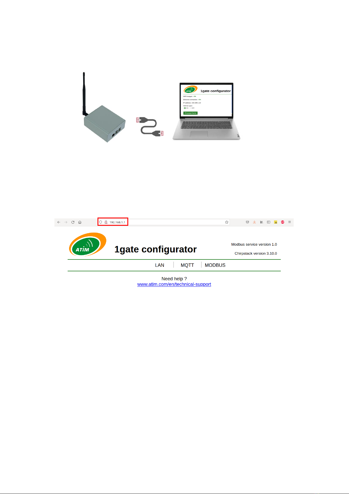
- Basic IT network knowledge is required to set up ATIM LoRaWAN gateways.
- Contact your IT service before installing the gateway.
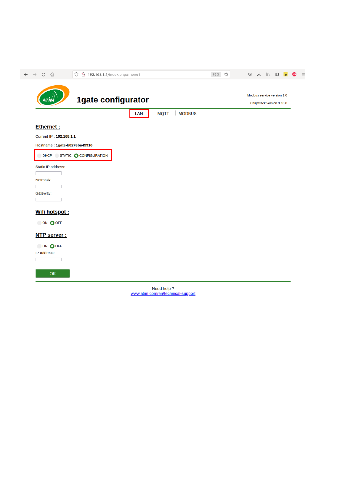
- Configuration options are explained in this document.
- Further details about Chirpstack network server are available on https://www.chirpstack.io/
- Gateway power supply is 5VDC 2,5A max.
LoRaWAN 868 MHz antenna should be connected to SMA connector before starting the gateway.
General hazard –Failure to follow the instructions presents a risk of equipment damage.
Electrical hazard –Failure to follow the instructions presents a risk of electrocution and physical injury.
WARNING: do not install this equipment near any source of heat or any source of humidity.
WARNING: for your safety, it is essential that this equipment be switched off and disconnected from mains
power before carrying out any technical operation on it.
WARNING: the safe operation of this product is ensured only when it is operated in accordance with its intended
use. Maintenance may only be performed by qualified personnel.

6
ATIM_1GATE_INDUS2_UG_EN_V1.2
Presentation
ATIM 1gate gateway is designed to set up a private LoRaWAN network based on open source Chirpstack server.
Devices’ uplink messages can then be forwarded using either:
•MQTT protocol
•MODBUS TCP protocol
When 1gate Gateway is configured in MQTT it behaves as a MQTT client and publishes uplink messages to an
external MQTT broker.
When 1gate gateway is configured in MODBUS, it behaves as a MODBUS TCP server (slave) whose registers values
can be extracted from external MODBUS master (for example a PLC).

7
ATIM_1GATE_INDUS2_UG_EN_V1.2
Connection to the gateway
To configure the gateway start connecting an ethernet cable between the gateway and a computer. The computer
should automatically connect to local gateway LAN network via DHCP.
Once connected, the gateway configuration page can be accessed through a web page using the default IP address:
192.168.1.1
Configuration changes can be made from this webpage.
Options can be changed with toggle switches and desired fields can be filled before clicking on OK button to confirm
form changes.
Rebooting the gateway can be necessary after changes, click the RESTART button when it appears.
Ethernet
CONFIGURATION mode (default)

8
ATIM_1GATE_INDUS2_UG_EN_V1.2
a. LAN tab
The LAN (Local Area Network) tab can be used to integrate the gateway in an existing ethernet network.
Connecting gateway to an existing ethernet network
Two methods are possible for the gateway to get an IP address: STATIC or DHCP.
•Static addressing : gateway will set a specific IP address, for that Static IP address, Netmask and Gateway fields
must be filled before confirming with OK.
•DHCP addressing : gateway will automatically get an IP address according to network DHCP server.

9
ATIM_1GATE_INDUS2_UG_EN_V1.2
Accessing gateway through ethernet network
Once connected to ethernet network, gateway configuration page can be accessed using either:
•Gateway IP address
•Gateway hostname
Gateway hostname is unique and composed of the EMAC address with format below:
1gate-[EMAC address]
NOTE
EMAC is written on gateway label.
To access configuration webpage, open a web browser and enter the URL below: http://1gate-[EMACaddress].local/.
Cloud / Internet
Administration
computer
Switch / Rooter
Gateway
STATIC or DHCP modes (default)
Ethernet
Ethernet

10
ATIM_1GATE_INDUS2_UG_EN_V1.2
Accessing gateway through WIFI hotspot
When WIFI hotspot option is set, the gateway broadcast a WIFI network.
This network can be used to configure the gateway without connecting to Ethernet network.
To connect to WIFI hotspot use SSID and WPA KEY written on gateway label.
Once connected to gateway WIFI, the configuration page can be accessed with IP address 192.168.1.1
IMPORTANT NOTE
Activating WIFI hotspot can result in IP conflicts
Time synchronization
Gateway time needs to be synchronized.
By default, the gateway will try to get reference time from the internet.
In case there is no internet access from the Ethernet network, an NTP server can be used filling the NTP IP address
fields and enabling NTP.

11
ATIM_1GATE_INDUS2_UG_EN_V1.2
b. MQTT tab
MQTT tab can be used to fill MQTT broker information.
When integration is set to MQTT, then all fields must be filled so that the gateway can connect to remote MQTT
broker.

12
ATIM_1GATE_INDUS2_UG_EN_V1.2
c. MODBUS tab
MODBUS tab can be used to see all devices registered and activated in the gateway.
The Last seen field indicates the date of the last uplink message that has been sent by device.

13
ATIM_1GATE_INDUS2_UG_EN_V1.2
MODBUS server
When MODBUS integration is chosen, devices uplink messages are stored in MODBUS registers. The gateway behaves
as MODBUS TCP server (slave) and registers can be read from external MODBUS master.
All data is encoded in hexadecimal.
50 registers (100 bytes) are allocated per device and can be divided into three parts:
- 4 registers are allocated to device EUI
- 4 registers are allocated to timestamp
- 42 registers are allocated to message data payload
EXEMPLE
For example, the tab below indicates:
Device EUI 70b3d59ba000a761
Timestamp 1416020f090739
Data payload 10cea0cea64
For each part, data is stacked on the right, which implies that lot of registers are set to zero, particularly if payload is short.
When a new device is registered and join Chirpstack LoRaWAN server, it will be added to the list automatically.
For example, if three devices have been registered on LoRaWAN network server first, then registers below will be set:
- Registers [0 - 49] allocated to device 1
- Registers [50 - 99] allocated to device 2
- Registers [100 - 149] allocated to device 3
If a device sends various type of message (for example life frames and data frames) no difference can be made,
frames are stored in the same registers, which means that earlier frame will erase older one.

14
ATIM_1GATE_INDUS2_UG_EN_V1.2
a. DevEUI
Device EUI is a unique 8 bytes id that is used to identify a LoRaWAN device.
This id is stored at the beginning of MODBUS registers to make sure device can be identified.
b. Timestamp
4 registers (8 bytes) are allocated to timestamp. Timestamp includes last uplink message date and time.
Each byte contains a part of the date/time (i.e. year, month, hour, )
001415070d140014 can be decoded as below:
Register
Byte
Description
Hexadecimal
Decimal
Register 4
Byte 4.1
NC
00
-
Byte 4.2
Century
14
20
Register 5
Byte 5.1
Year
15
21
Byte 5.2
Month
07
07
Register 6
Byte 6.1
Day
0d
13
Byte 6.2
Hour
14
20
Register 7
Byte 7.1
Minute
00
00
Byte 7.2
Second
14
20
Decoded timestamp is 2021/07/13 20:00:20.
c. Payload
Remaining 42 registers are allocated to device data payload.
Data payload comes from uplink LoRaWAN message (JSON format) such as below:
Message payload, base64 encoded
Message payload, hexadecimal encoded

15
ATIM_1GATE_INDUS2_UG_EN_V1.2
Data payload is written in MODBUS registers according to big-endian, starting from the last register allocated or
“stacked on the right”.
Registers that are not used are left to zero, this way data fields can be read from the same address with a constant
length of 42 registers, for example:
- To get device 1 payload consult address 8 hex (8 dec), length 2A hex (42 dec)
- To get device 2 payload consult address 3A hex (58 dec), length 2A hex (42 dec)
- To get device 3 payload consult address 6C hex (108 dec), length 2A hex (42 dec)
Data is encoded in hexadecimal; it contains several information that are relative to the product / device registered.
Please see specific product documentation.
Example 1
MR4 configured with 2 counters, devEUI 70B3D59BA000C27E and payload below:
To extract counter 1 registers 45, 46 and 47 must be read and then filtered to remove headers.
To extract counter 2 registers 48 and 49 must be read.
25
26
27
28
29
30
31
32
33
34
35
36
37
38
39
40
41
42
43
44
45
46
47
48
49
00
00
00
00
00
00
00
00
00
00
00
00
00
00
00
00
00
00
00
00
00
00
00
00
00
00
00
00
00
00
00
00
00
00
00
00
00
00
00
A0
04
00
00
00
85
14
00
00
00
1B
0
1
2
3
4
5
6
7
8
9
10
11
12
13
14
15
16
17
18
19
20
21
22
23
24
70
B3
D5
9B
A0
00
C2
7E
00
14
16
02
12
0F
05
2E
00
00
00
00
00
00
00
00
00
00
00
00
00
00
00
00
00
00
00
00
00
00
00
00
00
00
00
00
00
00
00
00
00
00
Payload header
Counter2
header
Counter2
Counter1
A00400000085140000001B
Counter1
header

16
ATIM_1GATE_INDUS2_UG_EN_V1.2
Example 2
MR4 configured with 1 counter, datalogging of 6 measurements every 10 minutes, devEUI 70B3D59BA000C27E and
payload below:
Example 3
DIND80 frame, devEUI 70B3D59BA000D3EC and payload below:
To extract counter 1 registers 34 and 35 must be read
To extract counter 2 registers 36 and 37 must be read
...
According to product configuration data extraction can require further operations that can be complicated on basic
PLCs.
From MODBUS tab it is also possible to reset registers: clicking on Reset table button deletes the entire table and
start allocation from scratch: first device emitting an uplink message will be allocated to registers 0-49, second device
to registers 50-99 and so on.
0
1
2
3
4
5
6
7
8
9
10
11
12
13
14
15
16
17
18
19
20
21
22
23
24
70
B3
D5
9B
A0
00
C2
7E
00
14
16
02
12
0F
05
2E
00
00
00
00
00
00
00
00
00
00
00
00
00
00
00
00
00
00
00
00
00
00
00
00
00
00
00
00
00
00
00
00
00
00
25
26
27
28
29
30
31
32
33
34
35
36
37
38
39
40
41
42
43
44
45
46
47
48
49
00
00
00
00
00
00
00
00
00
00
00
00
00
00
00
00
00
00
00
00
00
00
00
00
00
00
A5
00
3C
04
00
00
00
04
00
00
00
03
00
00
00
1B
00
00
00
02
00
00
00
08
0
1
2
3
4
5
6
7
8
9
10
11
12
13
14
15
16
17
18
19
20
21
22
23
24
70
B3
D5
9B
A0
00
D3
EC
00
14
16
02
12
0F
05
2E
00
00
00
00
00
00
00
00
00
00
00
00
00
00
00
00
00
00
00
00
00
00
00
00
00
00
00
00
00
00
00
00
00
00
25
26
27
28
29
30
31
32
33
34
35
36
37
38
39
40
41
42
43
44
45
46
47
48
49
00
00
00
00
00
00
00
00
00
00
00
00
00
00
00
5E
FF
FF
00
00
00
0C
00
00
00
0B
00
00
00
08
00
00
00
06
00
00
00
07
00
00
00
08
00
00
00
06
00
00
00
00
Counter1 t-30min
A5003C040000001B0000000900000007000000050000000300000001
Counter1 t-20min
Counter1 t-40min
Counter1 t
Payload header
Counter1 t-50min
Counter1 t-10min
Counter1
header
5EFFFF0000000C0000000B000000080000000600000007000000080000000600000000
Counter1
Header
Counter2
Counter8
...

17
ATIM_1GATE_INDUS2_UG_EN_V1.2
MODBUS webpage also contains a link to download logs of MODBUS application for debug purposes.
d. Data extraction
To test MODBUS TCP connection to the gateway, a MODBUS emulator such as Kscada MODBUS DOCTOR can be used.
Please configure:
−IP address of the gateway that can be seen in the LAN tab
−Port is 502
−Slave ID is not specific since MODBUS server should respond to any slave ID
−Time Out can be left to 1000
−Mode HEXADECIMAL
−Register: the address corresponding to the device, for example
00h (0 dec) for the first device emitting
32h (50 dec) for the second device emitting
64h (100 dec) for the third device emitting
96h (150 dec) for the fourth device emitting ....
−Length: 32h (50 in decimal)
−Type 3 Holding Registers
Then click on CONNECTION, if connection is successful click on READING to get device data.

18
ATIM_1GATE_INDUS2_UG_EN_V1.2
LoRaWAN server Administration
Chirpstack is an open-source software stack than can be used to set up a local (private) LoRaWAN network.
a. Connection to Chirpstack web page
To access Chirpstack configuration page, open a web browser and enter the IP address of the gateway followed by
8080 port:
Alternatively, the gateway
hostname can be used such as
shown previously.
To connect to Chirpstack enter
the default IDs below:
−Username/email: admin
−Password: admin
First page is named Dashboard, it shows the activity of the gateway and devices:
Gateway settings can be changed from Gateway-profiles tab, such as device settings from Device-profiles tab.

19
ATIM_1GATE_INDUS2_UG_EN_V1.2
b. Device registration
To add devices to LoRaWAN network, select Applications tab and then click on defaultApplication.
NOTE
Initially no device should appear in the list.
For security reason, OTAA (Over The Air Activation) method is used to add devices.
Two IDs are necessary for that:
- A 8 bytes device EUI
- The 16 bytes application key attached to the devEUI
To add a device, click on +CREATE
In the GENERAL tab enter the device name and description and the Device EUI
Then select defaultDeviceProfile and confirm clicking on CREATE DEVICE
Device list
Table of contents
Other Atim Cloud Wireless Network Hardware manuals
Popular Network Hardware manuals by other brands

Viking
Viking DVA-2WA Application note

Digital Watchdog
Digital Watchdog Blackjack Ai DW-BJAiASL quick start guide

Sonoff
Sonoff MINIR4M instruction manual

Patton electronics
Patton electronics ForeFront 2616RC Specifications

3Com
3Com OfficeConnect Remote 510 user guide

Mobatime
Mobatime BU 190 S 48 Installation and operating

Infolock
Infolock INSIGHT DLP SENSOR 0610S Hardware installation guide

Sophos
Sophos RED 10 operating instructions

ADTRAN
ADTRAN NETVANTA OCTAL POE quick start

One Identity
One Identity Safeguard for Privileged Sessions 6.0 Series installation guide

Paradyne
Paradyne 8310 MVLt user guide

ADTRAN
ADTRAN ISU 128 user manual