ATLA COOP GAMMA Manual

1 Rev. 00
Built in year: 2008
OPERATING AND MAINTENANCE INSTRUCTIONS
PNEUMATIC CRIMPING
MACHINE
GAMMA

2 Rev. 00
List of contents
1 HOW TO USE AND KEEP THIS INSTRUCTIONS
HANDBOOK
1.1 Purpose and Allocation of these Instructions 1-1
1.2 Definitions and Terminology 1-2
1.3 Handbook's Layout 1-3
1.4 How to keep the instructions handbook 1-3
1.5 Updating 1-4
1.6 Terminology 1-4
2 GENERAL DESCRIPTION
2.1 Overall Dimensions and Technical Data 2-1
2.2 Duty 2-3
2.3 Standard Equipment 2-3
2.4 Guidelines for Safe Use 2-3
2.5 Suitable User 2-3
3 SPECIFICATIONS
3.1 General Description 3-1
3.2 Operation 3-3
3.3 Pneumatic System 3-4
4 INSTALLATION
4.1 Introduction 4-1
4.2 Trasport and Handling 4-1
4.3 Storing 4-2
4.4 Environmental conditions 4-2
4.5 Installation
4.6 Required Installation Characteristics 4-3

3 Rev. 00
5 OPERATING INSTRUCTIONS
5.1 Operating Commands and Control Devices 5-1
5.2 Other Commands on the Crimping Machine 5-2
5.3 How to start and stop the Machine 5-2
5.3.1 Start 5-2
5.3.2 Stop 5-2
5.4 Machining cycle 5-3
5.5 How to work a profile 5-4
5.5.1 How to adjust the Vertical Cylinder 5-4
5.5.2 How to adjust the Eccentric Guides 5-5
5.5.3 How to mount and adjust the Bracing Clamp 5-6
5.5.4 How to mount and adjust the Crimping Tools 5-7
5.5.5 How to adjust the Reference Forks 5-9
6 GUIDELINES FOR SAFE USE
6.1 General 6-1
6.2 Safety Devices 6-1
6.3 Protective Devices 6-2
6.4 Personal Protection Equipment 6-2
6.5 Residual Risks 6-2
7 MAINTENANCE
7.1 General 7-1
7.2 Routine Maintenance 7-1
7.2.1 How to clean the machine 7-2
7.2.2 How to drain condensate from the air regulator 7-2
7.2.3 Control of the oil level in the air regulator and filling up 7-3
7.2.4 How to lubricate the Machine 7-4
7.3 Troubleshooting 7-5
7.4 Remedial Maintenance 7-5

4 Rev. 00
7.5 Technical Service 7-5
8 DISMANTLING AND SCRAPPING INSTRUCTIONS
8.1 Removal of the Connections 8-1
8.2 Scrapping 8-1
9 ENCLOSED DOCUMENATION
9.1 List of the enclosed documents 9-1

5 Rev. 00
LIST OF THE VALID PAGES
Section Total pages Date
Preliminary Text From pag. i to pag. vii July 2003
1 From pag. 1-1 to pag. 1-4 July 2003
2 From pag. 2-1 to pag. 2-3 July 2003
3 From pag. 3-1 to pag. 3-5 July 2003
4 From pag. 4-1 to pag. 4-3 July 2003
5 From pag. 5-1 to pag. 5-9 July 2003
6 From pag. 6-1 to pag. 6-3 July 2003
7 From pag. 7-1 to pag. 7-5 July 2003
8 Pag. 8-1 July 2003
9 Pag. 9-1 July 2003

6 Rev. 00
LIST OF THE REVISED AND/OR ADDED PAGES
Rev. Description DatePage

7 Rev. 00
MANUFACTURING DATA
MANUFACTURER ________ ATLA COOP SCRL _________________________
_______
ADRESS ______________________________________________________________
_______________________________________________________________
TELEFON N° _________________________________________________________
Via Bolognese, 5 - Loc. TaiutiS. Piero a Sieve -
Firenze (Italy)
tel. 055/8498428 - fax 055/8498430
The same rating is fixed on the machine with indication of the machine data and the manufacturer's
data.

Built in year: 2005
Rev. 00
OPERATING AND MAINTENANCE INSTRUCTIONS
PNEUMATIC CRIMPING
MACHINE
GAMMA

9 Rev. 00
1 HOW TO USE AND KEEP THIS INSTRUCTIONS
HANDBOOK
1.1 Purpose and Allocation of these Instructions
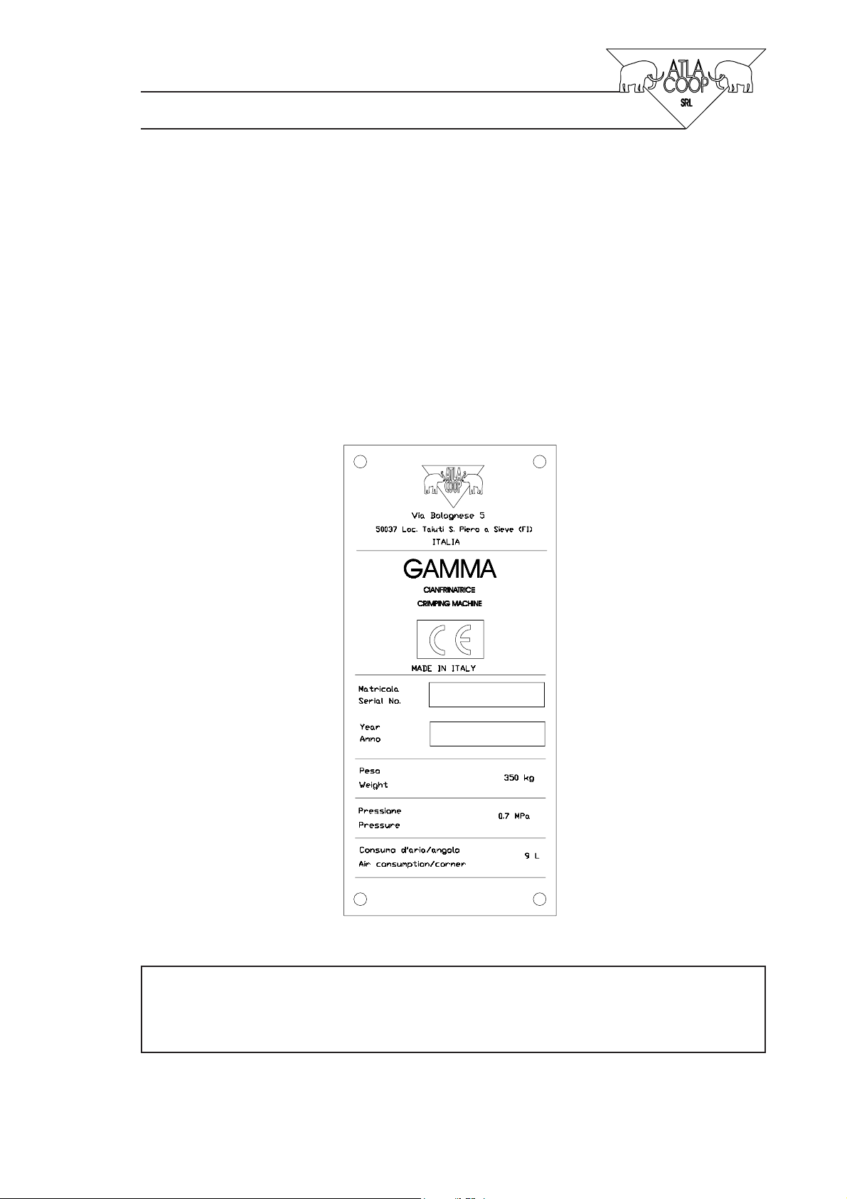
This Instructions Handbook contains the necessary instructions for the correct use and maintenance
of the pneumatic crimping machine called GAMMA.
The machine must always be accompanied by these instructions throughout its whole lifetime. In the
event that the machine is sold or given in possession of a third party, it's necessary to transfer also
these instructions together with all the other enclosed documents in order to guarantee the user's and
operator's safety.
This handbook allows to perform the following operations :
— installation
— regulation
— exploitation
— maintenance
— scrapping
This handbook is allocated both to the user and to the operator in charge of these operations. The
failure to use the machine in accordance with the instructions contained in this handbook will release
the company ATLA COOP from any liability.
The company ATLA COOP shall not be liable for incidental or consequential damages resulting
from the following circumstances :
— Abuse or misuse of the machine
— Failure to use the machine in accordance with the technical or safety standards in force in a
given country
— Installation of the machine in a manner inconsistent with the instructions contained in this
handbook
— Failure to perform the forseen maintenance
— Alteration, modification
— Replacement of not original or not specific spare parts
— Failure to use the machine in accordance with the instructions of this handbook
These instructions cannot be used as a point of reference for adaptations, changes or adjustments to
upgrade the machine from its normal purpose. If this happens ATLA COOPshall be released from
any liability. ATLA COOP shall not be liable for circumstances other than defects in materials or
workmanship.

10 Rev. 00
1.2 Definitions and terminology
— User
— Operator
— Machine
— The"User" is the person who is in charge, because of his/her qualification, of the permanent
operation of the machine.
— The "Operator" is the person who is in charge of machine installation, putting into service,
adjustment, maintenance, cleaning, repair and trasport.
— In these instructions the words "machine" and "crimping machine" refers to the crimping machine
called GAMMA.
All maintenance and operating works must be carried out by persons qualified for such works. The
qualification degree refers to the works and the operations, which the operator is assigned to in
accordance with the manufacturer's instructions.
Qualification 1
The person with this qualification has no specific education, but he/she is qualified to simply
operate the machine. He/she will reach this qualification by means of thorough reading of these
instructions and training by ATLA COOP Service.
Qualification 2
The person with this qualification has a specific education in electronically controlled Automatic
Machines with a specific knowledge on how to carry out mechanical and electrical works. This
qualification enables the person to perform regulation and routine or remedial maintenance
works in accordance with these operating and maintenance instructions. The person will reach
this qualification by means of thorough reading of these instructions and training by ATLA COOP
Service.

11 Rev. 00
Qualifica 3
The person with this qualification has a specific education in electronically controlled Automatic
Machines and he/she is qualified for electric works. This qualification enables the person to
perform installation, regulation, routine or remedial maintenance works. The person will reach
this qualification by means of thorough reading of these instructions and training by ATLA COOP
Service.
1.3 Handbook's Layout
This handbook has been drafted and drawn up in compliance with the Machinery Directive (98/
37)CE and the technical and safety standards there quoted when applicable. The handbook's layout
is as follows:
— Page for the indentification of the rating (relating to the specific machine).
— List of the valid pages.
— List of the revised pages.
— Table of contents.
— Enclosed documents.
The enclosed documents enable the purchaser to personalize the machine to his/her needs. The list
of the valid pages contains the indication of quantity of pages of each section in order to check the
handbook's completeness.
1.4 How to keep this Handbook
This handbook must always be available to the user in order to enable him/her to operate correctly
the machine. Therefore, this handbook must be kept near the machine in a dry place provided for
the purpose, far from heat sources and any other climatic condition that may damage it. To achieve
a precise knowledge of the machine it is necessary that the handbook is complete. Check therefore
its completeness with reference to the list of contents. In case of its lost or damage, please, contact
the company ATLA COOP for a further copy.

12 Rev. 00
1.5 Updating
New updated editions of these Operating and Maintenance Instructions may be made without notice.
Notice will be given only in case of improvement in the machine's safety level and in case of changes
that modify the machine functioning.
These instructions must also be updated after each operation carried out by ATLA COOP Service,
which result in a change of the machine layout, operating or control. It may be also necessary to
update the list of the revised pages. In this case, ATLA COOP undertakes to provide the updated
revised pages, together with a new copy of their list and the updated table of the revisions there
contained.
In order to avoid contradictions between the instructions and the operations to be carried out, the
user must take care to replace the old pages with the new ones.
! ! ! WARNING ! ! !
Contradictions between these instructions and the
machine layout may cause risks for the user. It is therefore
important to follow the above advice.
1.6 Terminology
These Operating and Maintenance Instructions contain important advice for the user/operator on
how specific procedures have to be performed. The types of advice are as follows:
NOTE: Advice on special machine characteristics in order to help the operator to optimize
his/her operating.
CAUTION: Very important advice on what is to be done/or not to be done before operating
the machine in order to avoid damage to the machine.
WARNING: Very important advice on what is to be done/or not to be done before operating
the machine in order to avoid injuries to persons.

13 Rev. 00
2 GENERAL DESCRIPTION
2.1 Overall dimensions and technical data
The overall dimensions of the complete crimping machine GAMMA are shown in fig. 2-1. The
measures are in millimeters.
! NOTE
!
While installing ensure 100cm clearance all around the
machine to allow user's free movement.
The following data refer to the machine technical characteristics, performance and capacity.
— Machine height: 1308 mm;
— Machine width: 835 mm (1946 mm with support profiles);
— Machine lenght: 786 mm (1221 mm with support profiles);
— Machine weight: 350 kg;
— Air supply: 0,7 MPa (7 bar);
— Air absorption: 9 l/corner;
— Max operating stroke: 350 mm;
— Knives operating stroke: max 12 mm;
— Sound-intensity level: 73 dB(A).

14 Rev. 00
Fig. 2.1
1221
786
928
1308
1946
835

15 Rev. 00
2.2 Duty
The crimping machine is designed to effect the assembly (crimping) of aluminium and PVC/iron
profiles.
Max machinable profiles sizes:
— Max profile height : max 120 mm;
— Max profile thickness (aluminium): max 3 mm;
— Max operating range of crimping heads and reference forks: from 23,5 to 63,5.
2.3 Standard Equipment
The machine is not equipped with accessories or special tools which could change her functioning.
The machine comes complete with the following accessories:
— n° 1 setscrew wrench 8 mm;
— n° 2 support profiles.
2.4 Guidelines for Safe Use
The crimping machine GAMMA is designed and constructed in compliance with the relevant CE
Directives and the safety standards there quoted.
In case of malfunctions not forseen or foreseeable in these instructions, please, contact ATLA COOP
Service, before operating with the machine. The company ATLA COOP shall not be liable for
incidental or consequential damages resulting from abuse or misuse beyond its control.
2.5 Suitable User
The user operating with the machine must have Qualification 1, in order to guarantee a good knowledge
of the correct machine operation. The above mentioned qualification can be reached through thorough
reading of these Operating and Maintenance Instructions and training by already qualified personnel.

16 Rev. 00
3 SPECIFICATIONS
3.1 General Description
The machine is designed and constructed for crimping and correct assembly of aluminium profiles
through the pneumatically controlled system.
The machine operating is semiautomatic, the machining cycle of various units are manual controlled
by user who always stays outside danger's area.
The macchina is equipped with the foot pedals for the operation control during the machining cycle.
Fig. 3.1 shows the various parts of the crimping machine.
See section 5 for a detailed description of the control devices.
See section 6 for a detailed description of the safety devices.

17 Rev. 00
Fig. 3.1
1Machine bed
2Air connection- pressure regulator
3Safety guard for work area
4Foot pedals
5Vertical cylinder for clamping
6Crimping knives
7Clamp unit with bracing clamp
8Reference forks unit
9Crimping head
10 Eccentric guide
-Support profiles (not shown)
1
2
3
4
5
6
7
8
9
10

18 Rev. 00
3.2 Operation
The crimping machine GAMMA is designed and constructed to join and close profile corners
through crimping. The entire machining cycle is controlled by pneumatic cylinders built inside the
machine bed, exclusive of the vertical cylinder (5, fig. 3.1) put on the worktable. For this reason the
machine is supplied exclusively with air supply from outside (6÷7 bar).
The machine operation is semiautomatic and every machining cycle is performed after previous
user's consent.
The machining cycle is very simple: once the profile is manually positioned against the reference
works (8, fig. 3.1) (after opening the safety cover), the user must close the cover in order to allow
the clamp's movement (7, fig. 3.1). The bracing clamp rotates from the machine bed and then moves
forward until it presses the internal profile corner.
Now, the user can active the profile crimping, which comes by means of knives (6, fig. 3.1) built on
the crimping heads.
In particular, the clamp's rotation is reached by means of the pneumatic cylinder controlled by the
pneumatic end-stroke built on the cylinder for clamp's forward movement. It allows to activate the
rotation only when the clamp is in the backward position.
The forward movement of the clamp is reached be means of the oleo-pneumatic cylinder driven by
an oil vessel supplied with pressure of 2,5 bar. The air goes into the vessel causing the oil's
compression that generates the forward movement of the clamp until the end-stroke; then the special
valve blocks the oil inside in order to allow the clamp to stay in position during the crimping cycle.
The crimping knives are driven by the other cylinder, vertically put inside the machine bed, which
activates a leverage actuating simultaneously the forward movement of the crimping knives. Together
with the knives is activated the vertical cylinder.
All movements are controlled through the pneumatic end-strokes (also control of the cover).
Various regulations of the machine are effected through the manual devices and by help of the
graduated scales.

19 Rev. 00
3.3 Pneumatic System
The machine is fitted only with pneumatic system whose diagrams are enclosed in this handbook in
order to allow complete training and knowledge of the machine (the diagram is complete with the
table which describes the parts of it ).

20 Rev. 00
Table of contents