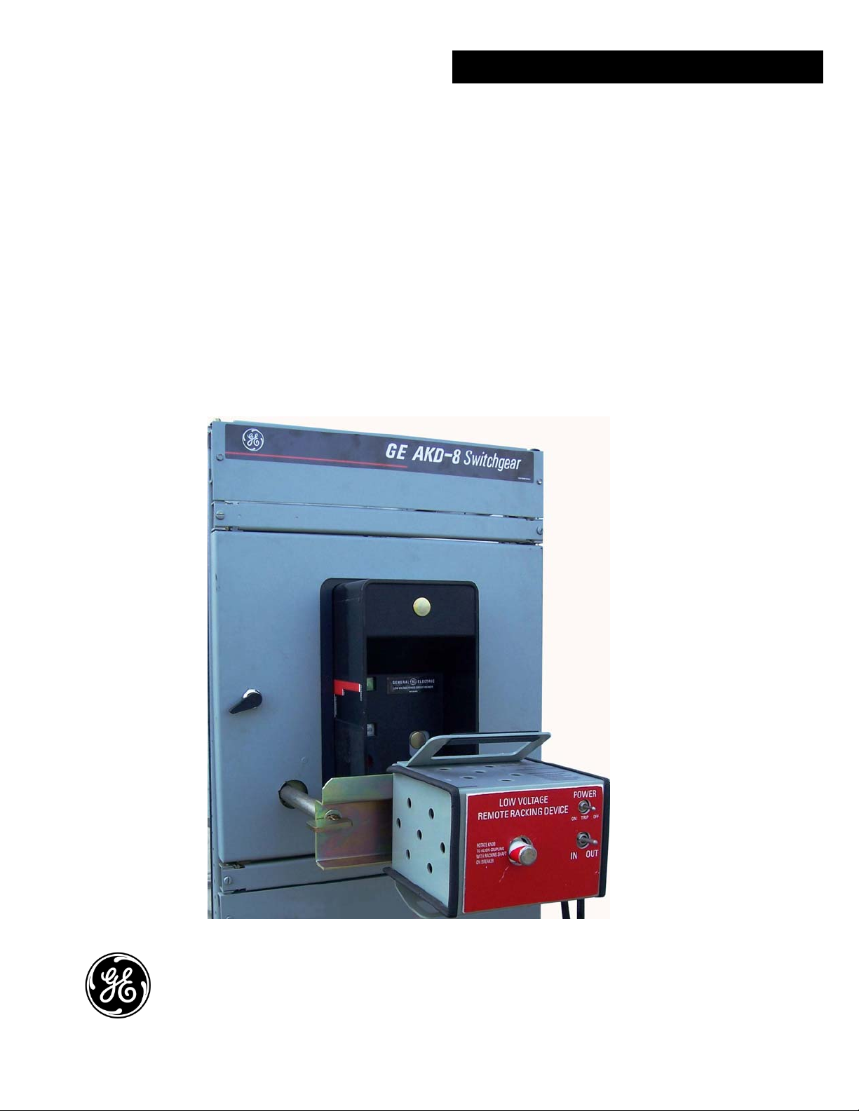
Remote Racking Operator for AKR BREAKERS
4
Section 3. Description
3-1 Description of Small Frame Remote
Racking Operator – 800A-2000A AKR
Breakers
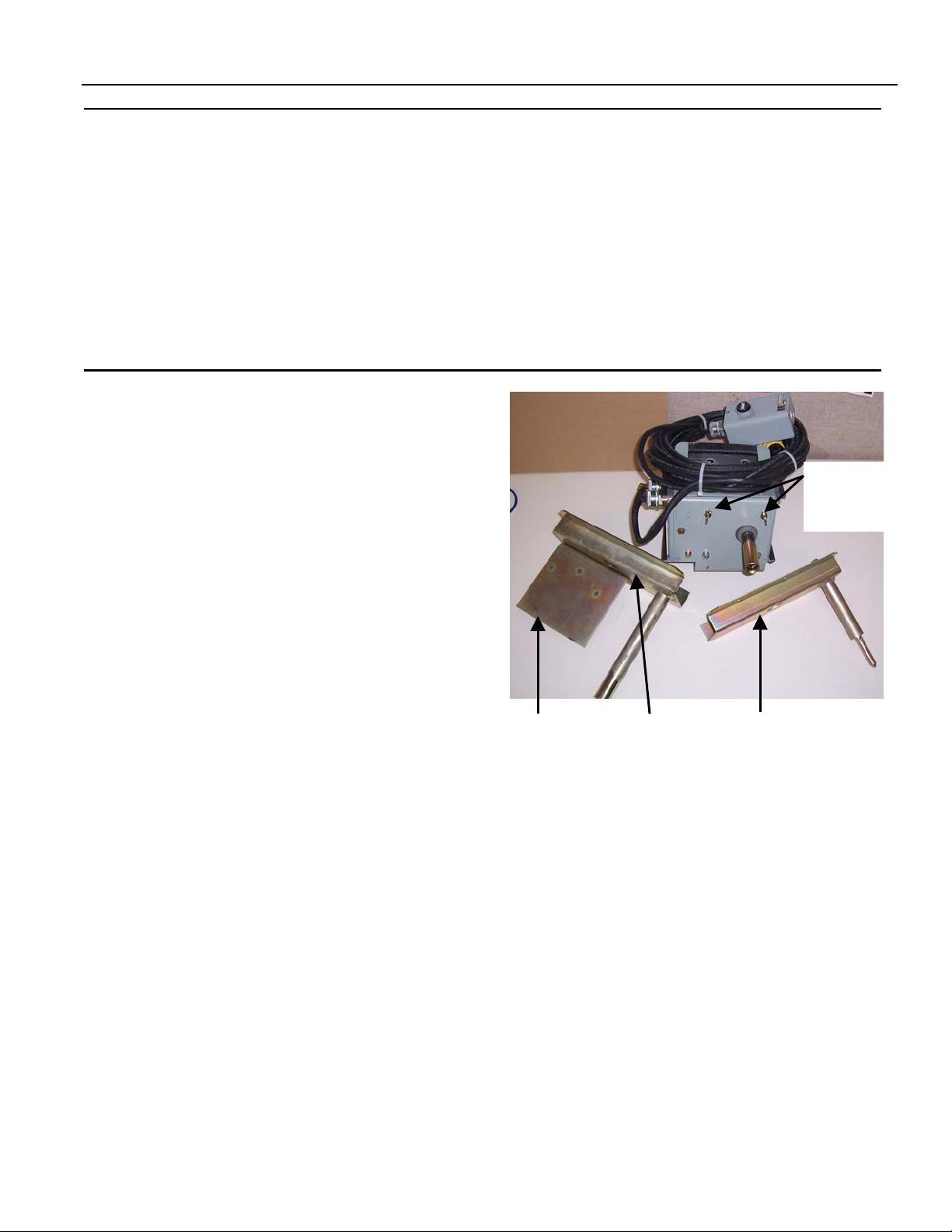
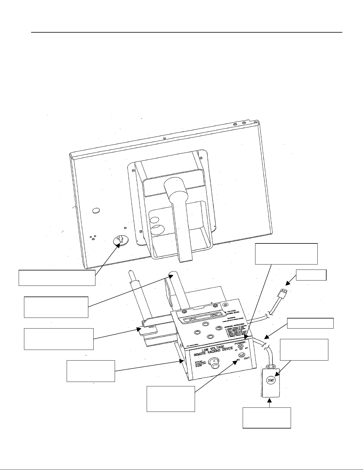
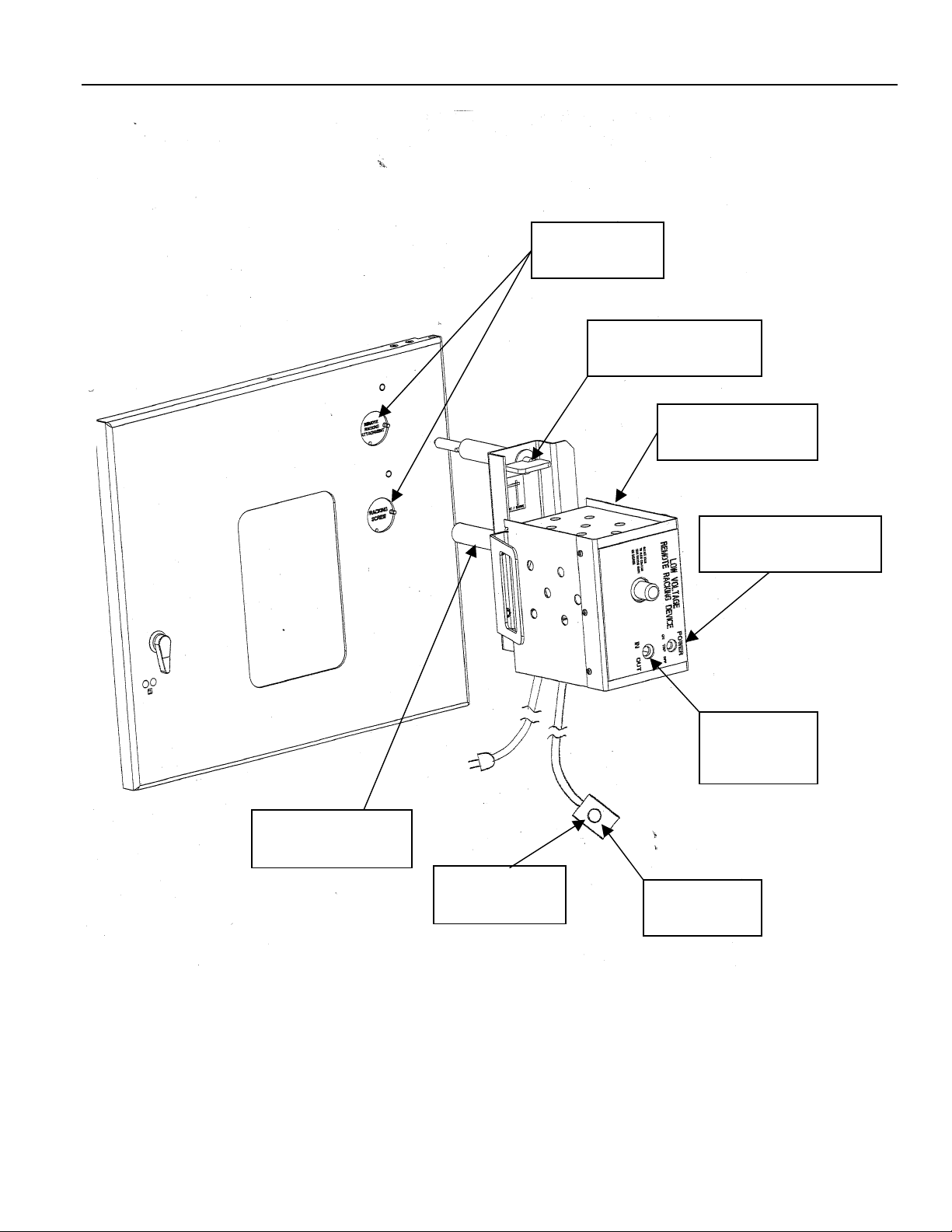
The remote racking operator consists of a drive
train, control switches, and attachment
brackets. The drive train is made of a gear
motor housing (1, Fig. 2), and a square drive
coupler (2, Fig. 2), which couples to the breaker
drawout mechanism.
Two control switches and a circuit breaker are
included with each remote racking operator.
The start switch (3, Fig. 2) housed in the hand-
held box (4, Fig. 2) controls the power to the
motor. Pushing the button closes the switch
and in turn supplies power to the motor. This
control switch is spring loaded; therefore,
continuous pressure on the button is required
to keep the motor running. The motor
directional toggle switch (5, Fig. 2) is mounted
on the motor housing. Two positions are
provided, “IN” and “OUT”. For racking toward
the CONNECT position, the switch should be set
to “IN”. For racking toward the DISCONNECT
position, the switch should be set to “OUT”. The
circuit breaker (6, Fig. 2) senses the motor stall
current when the breaker reaches the end of its
travel, which causes the motor to stall. The
higher motor stall current trips the circuit
breaker to the OFF position and in turn shuts off
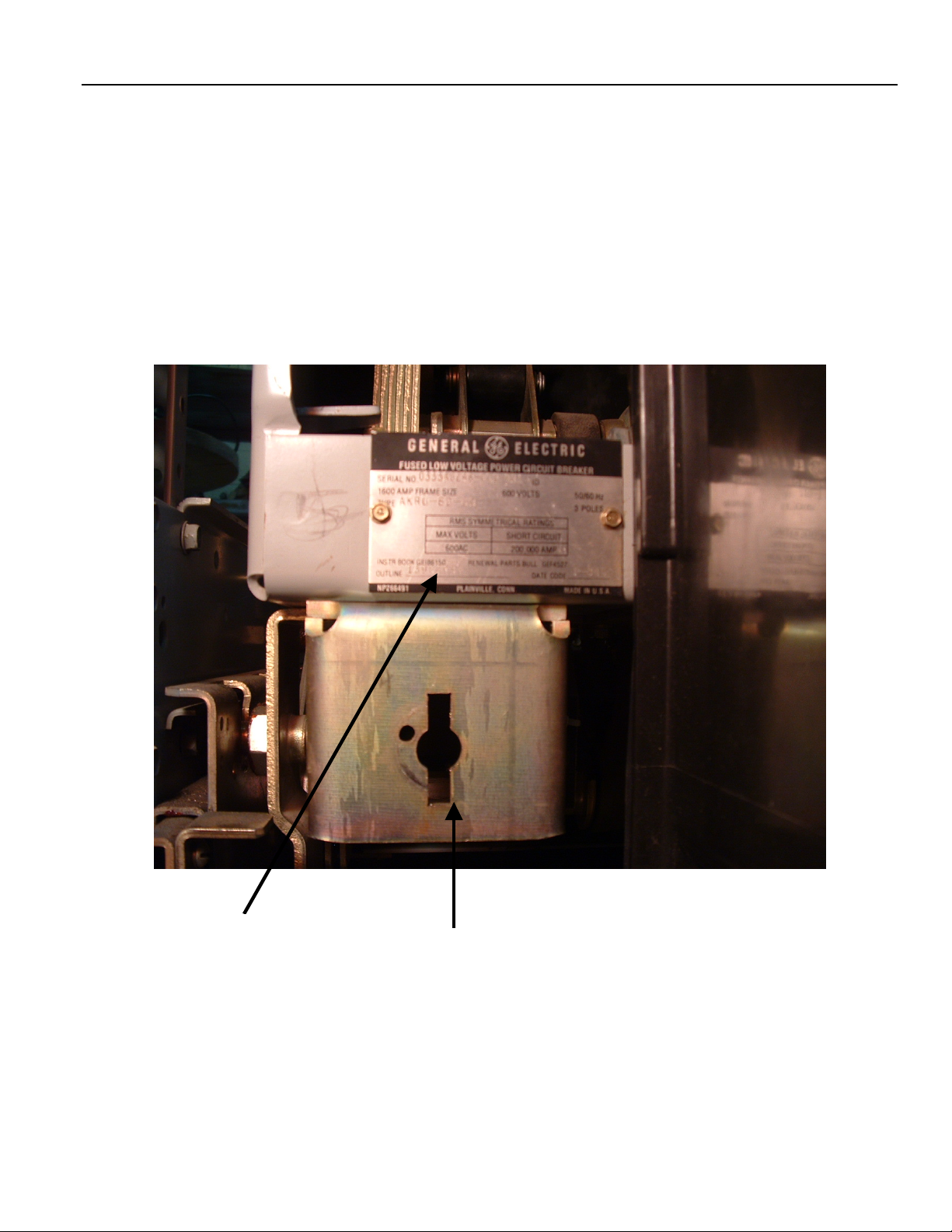
the power to the motor. The latch rod (7, Fig. 2)
is designed to provide the means for attaching
the remote racking operator to the front of the
Small Frame Breaker. The latch rod (7, Fig. 2)
hooks into the breaker mounting clip (8, Fig. 2)
for mounting the remote racking operator to
the breaker.
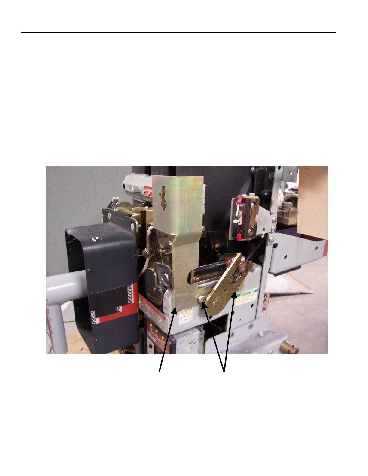
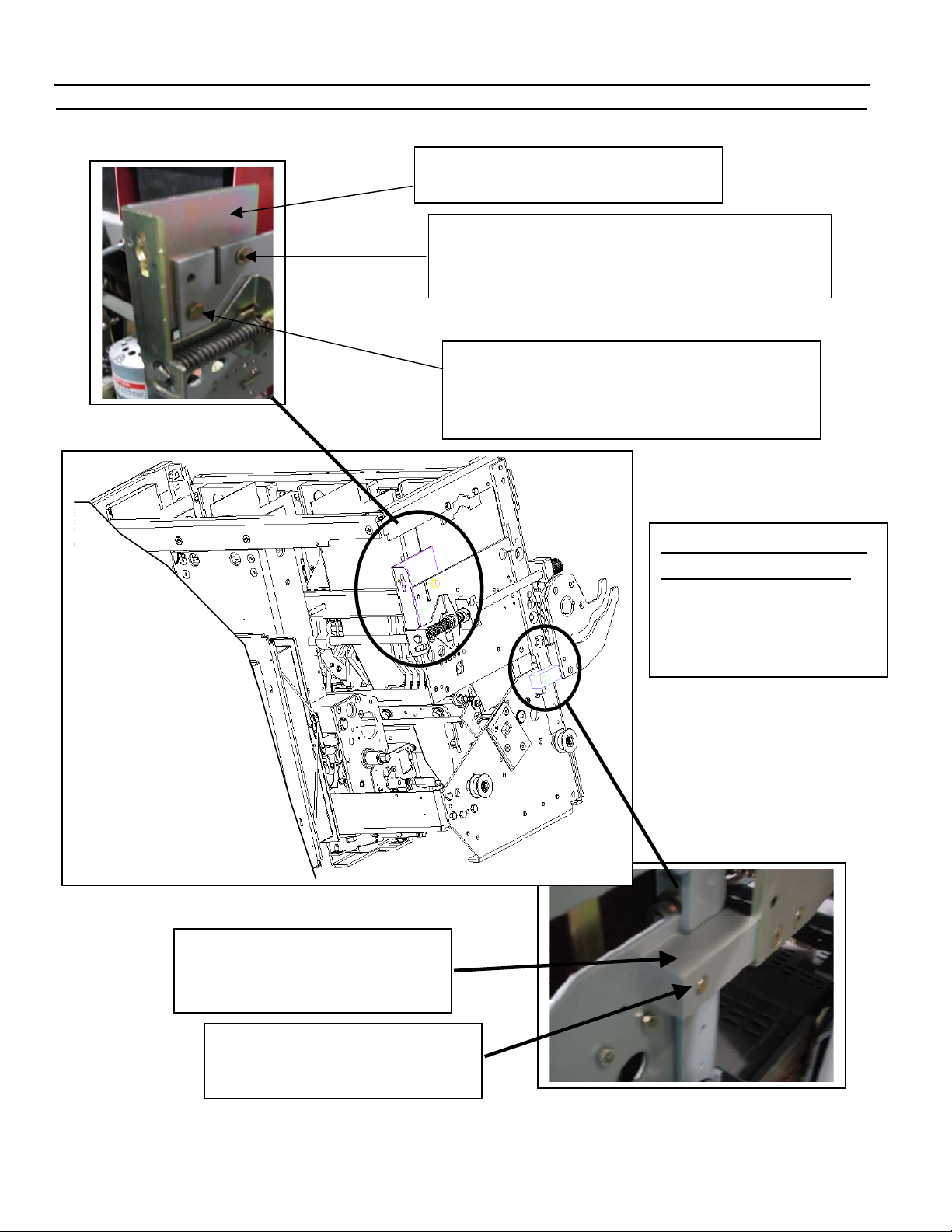
Modification to Existing Small Frame Breakers
Before attaching the remote racking operator
to the existing AKR 30/50 and AKR 30s breakers,
mounting brackets must be added to the
breaker. On the AKR 30S breaker, a mounting
bracket must be mounted on the right side of
the breaker just above the existing racking
screw. Refer to page 6 for the installation
instructions and kit number.
On the AKR 30/50 breaker, a mounting bracket
must be added to the left side of the
escutcheon on the breaker frame. Refer to
page 7 for the installation instructions and kit
number.
Refer to pages 12 and 13 for field modification
to existing breaker doors.
ATTACHING / REMOVING DEVICE
Attaching the Remote Racking Operator to
the Small Frame AKR circuit breaker.
The circuit breaker must be in the OPEN position
before attempting to attach the remote racking
operator to the breaker. On the AKR 30/50
breaker, push the trip button and slide the
racking screw cover in the breaker escutcheon
to the right. Next, slide the remote racking
attachment cover on the cubicle door to the
left. This will expose an opening in the breaker
cubicle door. On the AKR 30S breaker cubicle
door, slide either the upper or lower racking
screw access cover (located on the upper right
corner of the breaker cubicle door) to the left.
This will expose two openings in the cubicle
door. Position the remote racking operator so
that the square drive coupling is aligned with
the square shaft of the drawout (racking)
mechanism and the ¼ -turn latch rod engages
the breaker frame. Push the remote racking
operator toward the breaker to engage the
square drive coupling with the shaft of the
racking mechanism. If the coupling and the
shaft are not in alignment, rotate the motor
shaft extension on the back of the motor
housing in either direction until the square drive
aligns with the square racking shaft. When they
are in alignment, the remote racking operator