manuals.online logo
Brands
  1. Home
  2. •
  3. Brands
  4. •
  5. Atlantic
  6. •
  7. Boiler
  8. •
  9. Atlantic ygnis Pyronox LRP User manual

Atlantic ygnis Pyronox LRP User manual

This manual suits for next models

2

Other Atlantic Boiler manuals

Atlantic CONDENSINOX 40 Quick start guide

Atlantic

Atlantic CONDENSINOX 40 Quick start guide

Atlantic CORKLIM 500 Quick start guide

Atlantic

Atlantic CORKLIM 500 Quick start guide

Atlantic VF 40 Specification sheet

Atlantic

Atlantic VF 40 Specification sheet
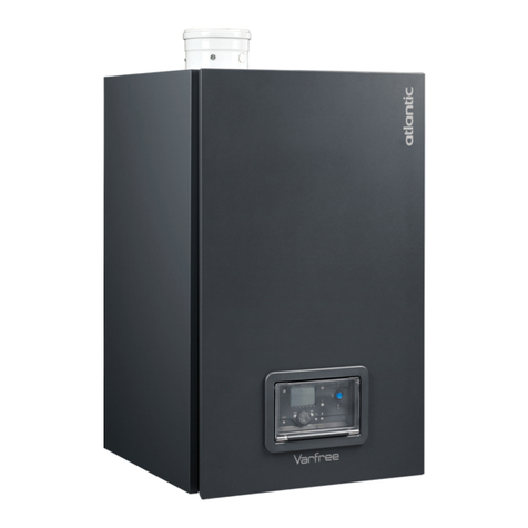
Atlantic Varmax Twin Parts list manual

Atlantic

Atlantic Varmax Twin Parts list manual

Atlantic MULTI ELEC User manual

Atlantic

Atlantic MULTI ELEC User manual

Atlantic HPWH 200 Lt Owner's manual

Atlantic

Atlantic HPWH 200 Lt Owner's manual

Atlantic VARFREE User manual

Atlantic

Atlantic VARFREE User manual

Popular Boiler manuals by other brands

IDEAL IMAX XTRA EL 320 user guide

IDEAL

IDEAL IMAX XTRA EL 320 user guide

UTICA BOILERS BC3D Installation, operation & maintenance manual

UTICA BOILERS

UTICA BOILERS BC3D Installation, operation & maintenance manual

Lochinvar SOLUTION 260000 Installation & service manual

Lochinvar

Lochinvar SOLUTION 260000 Installation & service manual

Weil-McLain EG 6 Series manual

Weil-McLain

Weil-McLain EG 6 Series manual

RBI LCD Series Installation & operation manual

RBI

RBI LCD Series Installation & operation manual

Baxi MainEco Combi 28 Installation and service manual

Baxi

Baxi MainEco Combi 28 Installation and service manual

Unical ALKON R 24 Installation and Servicing Manual

Unical

Unical ALKON R 24 Installation and Servicing Manual

Automatic Heating Gasogen Installation and Servicing Manual

Automatic Heating

Automatic Heating Gasogen Installation and Servicing Manual

Viessmann VITORADIAL 300-T Type VR3 Service instructions for contractors

Viessmann

Viessmann VITORADIAL 300-T Type VR3 Service instructions for contractors

Alpha GasSaver GS-1 Installation and servicing instructions

Alpha

Alpha GasSaver GS-1 Installation and servicing instructions

Baxi ROCA LAURA PLUS 28/28 Operating, cleaning and maintenance instructions for the user

Baxi

Baxi ROCA LAURA PLUS 28/28 Operating, cleaning and maintenance instructions for the user

Vaillant uniSTOR VIH SW GB 500 BES operating instructions

Vaillant

Vaillant uniSTOR VIH SW GB 500 BES operating instructions

Kärcher HWE 4000 Gas manual

Kärcher

Kärcher HWE 4000 Gas manual

Radijator BIO max 23.1 instruction manual

Radijator

Radijator BIO max 23.1 instruction manual

Granby BKC Installation, operation and maintenance manual

Granby

Granby BKC Installation, operation and maintenance manual

Brunner BSV 20 Instructions for use

Brunner

Brunner BSV 20 Instructions for use

Potterton 50e Installation and Servicing Manual

Potterton

Potterton 50e Installation and Servicing Manual

UTICA BOILERS TriFire Assembly instructions

UTICA BOILERS

UTICA BOILERS TriFire Assembly instructions

manuals.online logo
manuals.online logoBrands
  • About & Mission
  • Contact us
  • Privacy Policy
  • Terms and Conditions

Copyright 2025 Manuals.Online. All Rights Reserved.

ZUS aller Montageanleitungen Pyronox LRP, LRP-NT Plus Edition 15.06.2005
Artikelnummer: 409084, Zchg. 21732_m-a.pfd
Pyronox
LRP, LRP NT Plus
Montageanleitungen
Instruction de montage
Assembly guide
Montaggio guida
Montaje
Montageaanwijzing
Pyronox
2 Edition 15.06.2005
Inhaltsverzeichnis / Sommaire
Table of contents / Indice
Ìndice / Inhoud
Standard / standard
standard / standard
estàndar / norm
1. Turbulatoren / Turbulateurs 409085 21733
Turbulators / Turbulatori
Turbuladores / Turbulators
2. Ausstopfen der Türöffnung beim Brenneranbau 408537 21720
Bouchage de l’ouverture de la porte lors du montage du brûleur
Filling the door opening during burner installation
Tamponare il vano sportello durante il montaggio del bruciatore
Tapamiento de la apertura de puerta en la parte del quemador
Opvullen van de deuropening bij de montage van de brander
3. Montage Kesselschaltfeld und Verschalung 408304 21549
Montage tableau de commande et habillage
Mounting the boiler control panel and the casing
Montaggio del pannello di comando della caldaia e della cappottatura
Montaje panel de mando de la caldera y envoltura
Montage ketelschakelpaneel en bekisting
Optional / option
optional / opzionale
opcional / optioneel
4. Schwingungsdämpfer / Plots antivibratiles 409086 21734
Vibration dampers / Antivibranti
Elementos antivibrantes / Trillingsdempers
5. Türschwenkrichtung ändern 409087 21735
Modification du sens de rotation de la porte
Changing the door opening
Cambiare il lato di apertura dello sportello
Cambiar dirección de giro de la puerta
Draairichting van de deur veranderen
21733_m--.pdf
Art.-Nr. : 409085
Version: 01.06.2005
Pyronox
LRP, LRP-NT Plus, LRP-E
Turbulatoren
Turbulateurs
Turbulators
Turbulatori
Turbuladores
Turbulators
Montageanleitung Instruction de montage
Assembly guide Istruzioni al montaggio
Instrucciones de montaje Montagehandleiding
2
Rauchrohr mit Turbulator
Tube de fumée avec turbulateur
Flue gas pipe with turbulator
Tubo di fumo con turbolatore
Tubo de humos con turbulador
Vlampijp met turbulator
Rauchrohr ohne Turbulator
Tube de fumée sans turbulateur
Flue gas pipe without turbulator
Tubo di fumo senza turbolatore
Tubo de humos sin turbulador
Vlampijp zonder turbulator
Type 1 – 6
Type 7 – 11
Type 12 – 14
Sämtliche Rauchrohre des 3. Zuges werden mit Turbulatoren ausgerüstet (Hinweiskleber auf der Kesseltüre
beachten). Die Turbulatoren müssen bis zum Anschlag in die Rohre geschoben werden.
Tous les tubes de fumée de la troisième ligne seront équipés de turbulateurs (tenir compte des indications sur
l’autocollant sur la porte de chaudière). Introduire les turbulateurs jusqu’à la butée dans les tubes.
All three flue gas pipes of the third yyy zug are equipped with turbulators (see the info stickers on the boiler
door). The turbulators must be pushed into the pipes all the way to the stop.
Tutti i tubi di fumo del 3° tiraggio vengono dotati di turbolatori (vedere l’adesivo sullo sportello della caldaia). I
turbolatori devono essere spinti fino alla battuta entro i tubi di fumo.
Todos los tubos de humos del 3er tiro se equiparán de turbuladores (observar etiquetas avisadoras en la
puerta de la caldera). Los turbuladores deben enchufarse hasta el tope en los tubos.
Alle vlampijpen van het derde kanaal worden uitgerust met turbulatoren (sticker op de keteldeur in acht nemen).
De turbulatoren moeten tot aan de aanslag in de pijpen worden geschoven.
21720_m--.pdf
Art.-Nr. : 408537
Version: 01.06.2005
Pyronox
LRP, LRP-NT Plus, LRP-E
Ausstopfen der Türöffnung beim Brenneranbau
Bouchage de l’ouverture de la porte lors du montage du brû-
leur
Filling the door opening during burner installation
Tamponare il vano sportello durante il montaggio del bruciato-
re
Tapamiento de la apertura de puerta en la parte del quemador
Opvullen van de deuropening bij de montage van de brander
Montageanleitung Instruction de montage
Assembly guide Istruzioni al montaggio
Instrucciones de montaje Montagehandleiding
2
Vor Inbetriebnahme des Heizkessels muss der Raum zwischen Brennerrohr und Türisolation mit der im Lie-
ferumfang enthaltenen Keramikfaser-Wolle satt ausgestopft werden.
Bien boucher avec de la laine de fibre céramique incluse dans l’ensemble de livraison l’espace entre le tube de
brûleur et l’isolation de la porte avant de mettre en marche la chaudière.
Before the boiler is commissioned, the space between the boiler pipe and the door insulation must be prop-
erly filled with the ceramic fibre insulation material included in the delivery.
Prima della messa in esercizio della caldaia lo spazio tra il tubo del bruciatore e l’isolamento dello sportello
deve essere tamponato con la lana di fibra ceramica a corredo.
Ante la puesta en marcha de la caldera, ha de taparse el espacio entre el tubo del quemador y el aislamiento
de la puerta con la fibra cerámica que forma parte del volumen de suministro.
Vóór de inwerkingstelling van de verwarmingsketel moet de ruimte tussen branderpijp en deurisolatie volledig
worden opgevuld met keramische wol, die tot de leveringsomvang behoort.
Keramikfaser-Wolle
Laine de fibre céramique
Ceramic fibre
Lana di fibra ceramica
Fibra cerámica
Keramische wol
21549_m-a.pdf
Art.-Nr.: 408304
Version: 15.06.2005
Pyronox LRP, LRP-NT Plus
Montage des Kesselschaltfeldes und der Verschalung
Montage du tableau de commande de la chaudière et de la jaquette
Boiler control panel and casing assembly
Montaggio del pannello di comando caldaia e del rivestimento
Montaje del panel de mando caldera y del revestimiento
Montage van het ketelschakelpaneel en de bekleding
Pyronox LRP, LRP-NT Plus
Seite 2 von 7
Achtung: Die Verschalung ist zu montieren, bevor der Kessel an den Kamin angeschlossen wird!
Inhalt:
Überprüfen Sie den Inhalt der Verpackung auf Ihre Vollständigkeit und auf eventuelle Transportschäden.
- Deckblech 1
- Seitenbleche 2
- Plastiktüte mit Schrauben
- Rückwand 3
- Frontabdeckung 4(optional in separater Verpackung)
- Kesselschaltfeld 5 (befindet sich bei
Lieferung im Brennraum)
Montageanleitung
- Deckblech 1über die vorgesehenen Bolzen 6auf den Druckkörper legen.
- Kesselschaltfeld 5auf das Deckblech legen, die Fühler durch die Öffnung im Deckblech in die Tauchhülsen ein-
führen.
Detaillierte Angaben zum Kesselschaltfeld finden Sie in den Dokumenten PYROMATIC (Art. 408525) oder
PYROTRONIC (Art. 408522).
- Kabel 8für die Brennersteuerung durch die unten vorgesehene Öffnung nach innen und seitlich links neben dem
Druckkörper nach oben führen. Dann durch die Öffnung im Deckblech 1in das Kesselschaltfeld einführen. An-
schliessend mit den Klemmbackenstutzen 9die Kabel auf die benötigte Länge (je nach Brenner) in den Schlitzen
der Öffnung fixieren. Die verbleibenden Kabel der Schaltfeldes durch die Öffnung und den Kabelkanal im Deck-
blech nach hinten führen.
- Kesselschaltfeld in die vorgesehene Halterung einstecken.
- Zungen unten an den Seitenblechen 2 um 90° nach vorne biegen. Diese dienen als Anschlag für die Magnete
der Frontabdeckung.
- Seitenbleche 2am Deckblech einhängen und beim Kesselfuss mit den Scheiben 10 und Schrauben 11 befesti-
gen.
- Zunge an der Rückwand 3um 90° nach innen biegen.
- Rückwand 3mit den beiliegenden Blechschrauben 7am Deckblech und den Seitenblechen befestigen.
- Frontabdeckung 4vorne am Deckblech einhängen und unten zwischen die Seitenbleche bis zum Magnetan-
schlag schieben.
Pyronox LRP, LRP-NT Plus
Seite 3 von 7
Attention: Monter la jaquette avant de raccorder la chaudière au conduit d'évacuation des fumées!
Fournitures:
Vérifier le contenu de l’emballage pour vous assurer qu’il est
complet et intact.
- Panneau supérieur 1
- Jaquette latérale 2
- Sachet avec vis
- Panneau arrière 3
- Panneau avant 4(option, placée dans
un colis séparé)
- Colis tableau de commande 5, placé dans le
foyer de la chaudière
Instructions de montage
- Emboîter le panneau supérieur 1sur les 4 axes 6placés sur le corps de chaudière.
- Placer le tableau de commande de la chaudière 5sur le panneau supérieur. Retirer la face avant du tableau (6
vis) et glisser les bulbes des thermostats et thermomètre, à travers l’ouverture du panneau supérieur, dans les
doigts de gant.
Pour des informations détaillées sur le tableau de commande, veuillez consulter les documents PYROMATIC
(Art. 408525) ou PYROTRONIC (Art. 408522).
- Passer les 2 câbles d’alimentation du brûleur 8à travers l’ouverture puis les faire passer sur le côté gauche du
corps de chaudière. Les introduire ensuite à travers l’ouverture centrale en partie basse avant. Maintenir les câ-
bles en place à l’aide des presse-étoupes 9à la longueur appropriée (selon le brûleur). Insérer le câble
d’alimentation électrique restant dans la goulotte centrale du panneau supérieur pour le ramener vers l’arrière de
la chaudière.
- Insérer le tableau de commande dans les 2 boulons du panneau supérieur. Remettre en place la face avant du
tableau et la fixer avec les 6 vis.
- Rabattre de 90° les languettes des panneaux latéraux 2, servant de butées pour les aimants de la façade.
- Accrocher les panneaux latéraux 2sur le panneau supérieur et les fixer au bas de la chaudière à l’aide des ron-
delles 10 et des vis 11.
- Rabattre de 90° la languette du panneau arrière 3 vers l’avant.
- Fixer le panneau arrière 3à l’aide des vis à tôle fournies 7sur les panneaux supérieur et latéraux.
- Accrocher la façade 4sur la partie avant du panneau supérieur et la pousser vers le bas entre les tôles latérales
jusqu’à la butée des aimants.
Pyronox LRP, LRP-NT Plus
Seite 4 von 7
Attention: Mount the casing prior to connecting the unit to the flue!
Contents:
Check the contents of the package against the
list below and inspect for damaged items.
- Lid 1
- Side panel 2
- Bag containing screws
- Rear wall 3
- Front panel 4(optional, separately packed)
- Boiler control panel 5(delivered inside
combustion chamber)
Assembly instructions
- Place the lid 1on the pins 6on the boiler body.
- Place the boiler control panel 5on the lid and introduce the probes through the lid opening and into the sleeves.
Please refer to the documents PYROMATIC (product no. 408525) or PYROTRONIC (product no. 408522) for de-
tailed information on the boiler control panels.
- Introduce burner control cable 8through the lower opening, push it in and then feed it upwards along the left
hand side of the boiler body. Then, insert the cable through the lid opening 1into the boiler control panel. Finally,
fasten cables at an adequate length (depending on burner) in the holes provided in the opening using the sleeve
of terminal 9. Insert remaining control panel cables through the opening and push them into the raceway towards
the back.
- Insert the control panel into the foreseen support.
- Fold the tongues at the bottom of the side panels 2by 90° towards the front. These serve as stops for the mag-
nets of the front panel.
- Snap the side plates 2to the lid and fasten them to boiler feet with washers 10 and screws 11.
- Fold the tongue of the rear panel 3by 90° towards the front.
- Fasten the rear panel 3to the lid and side panels with the screws provided 7.
- Snap the front panel 4to the front part of the lid and slide it downwards between the side plates until the magnets
click to the stops.