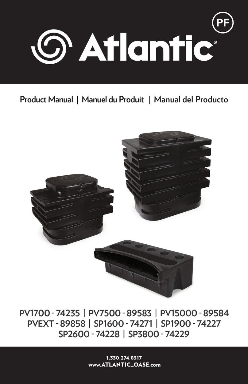
Atlantic PV1700 User manual

PV PV PV / PVEXT / PVEXT /
SP SP SP / SP
Product Manual
1.330.274.8317
www.ATLANTICWATERGARDENS.com
PF

Pond-free Features
Pond–free features exchange the open water of the pond for a gravel-topped excavation,
maximizing visual impact while minimizing headaches and maintenance. Typically, a pump
placed in a protective vault inside a lined reservoir continuously recirculates water over a
stream or waterfall. A bed of gravel hides the basin, vault and plumbing from view, leaving
only the stream and waterfall visible.
Table of Contents
Eco-Blox Reservoirs .................................................................................................................................................. 2
Gravel-Filled Reservoirs ...........................................................................................................................................3
Larger Basins ............................................................................................................................................................... 3
Streambed Construction ....................................................................................................................................... 4
Pump Vault
PV1700 Pump Vault Installation .......................................................................................................................... 4
Excavating and setting the PV1700 (Pond-free System) ......................................................................... 5
Plumbing the PV1700 (Pond-free System) ..................................................................................................... 5
Excavating and setting the PV1700 (Eco-Rise System) ............................................................................ 5
Plumbing the PV1700 (Eco-Rise System) ....................................................................................................... 6
PV1800/PV2300 Pump Vault Installation ...................................................................................................... 6
Excavating and setting the PV1800/PV2300 (Pond-free System) ..................................................... 6
For Larger Basin Volumes ...................................................................................................................................... 7
Plumbing the PV1800/PV2300 (Pond-free System) ................................................................................. 7
FastFalls
SP1600/1900/2600/3800 FastFalls Installation ........................................................................................ 7
Setting the FastFalls ................................................................................................................................................ 7
FastFalls Liner and Plumbing Attachment .................................................................................................... 8
Hiding the FastFalls ................................................................................................................................................. 9
Accessories
Triton Check Valve ................................................................................................................................................... 9
Discharge Pipe ‘Perfect Cut’ Reference Chart ............................................................................................ 9
AF1000 Auto Fill ...................................................................................................................................................... 10
Warranty ...................................................................................................................................................................... 11
2
Eco-Blox Reservoirs
Upon start-up, the pump draws water from the reservoir to fill the streambed, from top to
bottom, until the water overflows back into the reservoir to complete the cycle. We call the
amount of water needed to complete this cycle the ‘transitional’ water volume. If the reservoir
is too small, or the streambed built improperly, the water level in the reservoir can drop below
the top of the pump before cycling, leading to pump overheating and damage. We can
calculate the transitional water volume, then design the reservoir to hold at least three times
as much, so the water level in the reservoir never drops by more than one-third when the
pump is turned on, keeping the pump safely submerged at all times. Assuming that it will
take about 3" or 0.25 ft. of water to fill the stream and get the system recirculating, we can
calculate the transitional volume, minimum reservoir volume and Eco-Blox quantity by using
the formulas below:
WATER DEPTH CONVERSIONS
1" deep = 0.08'
2" deep = 0.16'
3" deep = 0.25'
4" deep = 0.33'
5" deep = 0.42'
6" deep = 0.50'
Stream Depth(.25ft) x Avg. Length(ft) x Avg. Width(ft) = Transitional Volume
Transitional Volume x 3 = Minimum Reservoir Volume
Minimum Reservoir Volume ÷ 4.2 = Number of Eco-Blox to fill Reservoir

Gravel-Filled Reservoirs
Because Eco-Blox are 96% void space, they allow the reservoir to be dug to just the size
required for the water volume needed. Backfilling with gravel fills 65% of the reservoir
with stone, leaving only the 35% that remains between the stones available for water
storage. This means that a gravel-filled basin will need to be three times larger than an
Eco-Blox basin to hold the same volume of water. That’s a lot more time, excavation,
additional soil removed, additional gravel to fill the hole, labor costs and cleanup.
For Larger Basin Volumes
For installations where a larger basin volume or a deeper basin is required, Atlantic oers
Pump Vault Extensions for both the PV1800 and PV2300. Each additional layer of Eco-Blox
increases the depth of your excavation by 17.5"; use one Extension for each additional layer.
Transitional Volume x 9 = Minimum Reservoir Volume
(when filled with gravel)
Transitional Volume x 3 = Minimum Reservoir Volume
(when filled with Eco-Blox)
3

Streambed Construction
The less the water level in the basin drops as the pump turns on and the stream fills, the better
for proper function. Proper streambed construction can reduce the amount of water needed for
this transition.
Since transitional volume is determined by how high the rock extends above the liner at the
spillways, minimizing that height reduces the amount of water necessary to fill the streambed.
The drawings to the right display two examples of proper streambed construction to keep the
transitional water to a maximum of 3-4” in depth.
Top of liner
Top of water Transitional Water
Top of liner
Top of water Transitional Water
Top of liner
Top of water
Transitional
Water X
Proper Streambed Construction
Improper Streambed Construction
Below is an example of improper streambed construction. Stone, gravel and foam can be
combined to make a barrier and create a waterfall, but that barrier will never be watertight.
When the pump is turned o, the water will always drain down to the highest point of the
liner. Improper construction greatly increases the amount of transitional water.
PV1700 Pump Vault Installation
The PV1700 is Atlantic’s most compact, easy to install pump vault. The PV1700 features an
incredibly strong enclosure, recessed panels on the front that can accommodate Triton
3-Way Diverters, cut lines on the back for 1½” and 2” pump discharges, and marked drill
points on the left and right sides for an Auto Fill.
4

Plumbing the PV1700 (Pond-free System)
The PV1700 has pump discharge step fittings
molded into each side of the enclosure. The
step fittings are labeled for 1½” or 2” PVC pipe
and have cut lines molded in for each size.
This allows the installer the flexibility to exit
out the left or right side. Use a hand saw to
remove the appropriate step fitting,
using the cut lines as a reference. The flat
panel on the back is for an overflow. The
two drill points near the top of the left
and right sides are for the installation
of an AF1000 Auto Fill (See Auto Fill
instructions on pg. 10).
OVERFLOW
PUMP
DISCHARGE
STEP FITTING
AF1000
AUTO FILL
OVERFLOW
Excavating and Setting the PV1700 (Pond-free System)
Once you have determined the proper size basin for your project, begin by deciding the
placement of the vault. The vault should be placed away from the
waterfall where the lid can be accessed easily.
The PV1700 flat panel will sit flush
against the Eco-Blox, so that water
can enter the pump vault. The area
where the pump vault will sit should
be dug 22” deep for the PV1700.
When using Eco-Blox, the pump vault
will recess lower than the Eco-Blox.
The area for the Eco-Blox to sit should
be dug 18” deep.
Level and tamp the bottom of the excavation, then install underlayment and EPDM liner.
Another layer of underlayment may be added on top of the liner for greater security before
setting the Eco-Blox and Pump Vault. Backfill the space between the Eco-Blox and the
excavation to lock them into place, either outside the liner with sand or clean fill, or inside
the liner with gravel ¾” or larger in diameter. Top the liner and basin with ¾” or larger gravel
or decorative stone. Smaller, more decorative gravel, landscape glass, etc. can be used to
cover the top of the basin, provided a denser mesh is installed beneath the material.
Excavating and Setting the PV1700 (Eco-Rise System)
The capacity of the basin will vary depending on the size, height and number of the
decorative fountain elements. For a general rule of thumb, make the basin at least twice the
width of the fountain piece(s) at the widest point. To capture the splash from taller pieces or
more aggressive flows, where added storage capacity isn’t desired or needed, excavate a
shallow 2-3” deep bowl around the basin and extend the liner out to at least twice the
height of the decorative elements in all directions. This technique will recapture as much
water as possible with minimum additional excavation.
Once you have determined the approximate size of the basin, lay out the Eco-Blox and
PV1700. The PV1700 should be placed away from the fountain piece where the lid can be
accessed easily. Place the flat panel of the PV1700 up against the Eco-Blox so water can
enter through the ports. Tailor the excavation to the shape of the Eco-Blox and PV1700 so
the vertical walls of the basin will support the outside walls of the Eco-Blox, leaving a few
extra inches all of the way around to make installation easier.
5

Plumbing the PV1700 (Eco-Rise System)
The recessed panels on the front right and left are designed to accommodate up to two
optional Triton 3-Way Diverters, to allow plumbing and individual valving of up to six
separately controlled decorative elements. To install, drill a 2¼” hole with a hole saw (not
included). The center point of the hole is marked on the panel.
The center raised area on the front of the PV1700
can be drilled for a single discharge of up to 1½” PVC
pipe. Your pipe size will determine the size of the
hole to drill. The flat panel on the back is designed
to accommodate an overflow. The two drill points
near the top of the left and right sides are for the
installation of an Auto Fill (See Auto Fill instructions
on pg. 10).
PV1800/PV2300 Pump Vault Installation
Excavating and Setting the PV1800/PV2300
Once you have determined a proper sized basin for your project, begin by deciding the
placement of the vault. The vault should be placed away from the waterfall where the lid
can be accessed easily. Excavate the entire area of the basin to a depth of 18”. This will
accommodate one layer of Eco-Blox. The area where the pump vault will sit should be dug
deeper to provide a sump area for the pump to sit, ensuring the pump will remain
completely submersed. If using a PV1800, dig this area to a depth of 22”, and for a PV2300,
a depth of 28”.
Dig the entire basin down to 20” below grade
and carefully level and tamp the bottom of the
excavation. This depth ensures the plumbing
fittings exit out on top of the Eco-Blox.
Install the underlayment and liner, then the
Eco-Blox and PV1700. An additional layer
of underlayment may be added for
greater security.
Backfill the space between the Eco-Blox and
the excavation to lock them into place, either
outside the liner with sand or
clean fill, or inside the liner with
gravel ¾” or larger in diameter.
Top the liner and basin with ¾”
or larger gravel or decorative stone.
6

Plumbing the PV1800/PV2300
Atlantic’s Pro Series Pump Vaults do not
come pre-drilled for the pump outlet.
Not having a pre-drilled pump outlet
gives the professional installer the
flexibility to choose which side of the
enclosure to exit and with what size
pipe. Drill points and cut lines have
been provided for 2” and 3” flex PVC.
Two panels at the top have been left
flat for custom plumbing applications
as well as the installation of an AF1000
Auto Fill and/or overflow. Recessed
areas and cut lines for 4” and 6” SDR35
have been provided on two bottom
panels. Pipe extensions can be added
to increase the flow of water into the
vault and also increase the ability to
channel debris into the vault.
2” & 3”
cutlines
4” & 6”
SDR35
FLAT PANELS
FOR AUTO FILL
INSTALLATION &
CUSTOM PLUMBING
For Larger Basin Volumes
For installations where a larger basin volume or a deeper basin is required, Atlantic oers
Pump Vault Extensions for both the PV1800 and PV2300. Each additional layer of Eco-Blox
increases the depth of your excavation by 17.5”; use one Extension for each additional layer.
Once excavation is complete, install
underlayment, pond liner, properly oriented
Eco-Blox and Pump Vault. Backfill the space
between the Eco-Blox/ Pump Vault and the
excavation to lock them into place, either
outside the liner with sand or clean fill, or
inside the liner with gravel ¾” or larger in
diameter. Top the liner and basin with ¾”
or larger gravel or decorative stone.
SP1600/SP1900/SP2600/SP3800 FastFalls Installation
Setting the Fastfalls
Place the FastFalls on a level bed of undisturbed soil if possible, to avoid settling. If
installing above existing grade, compact the area thoroughly. This critical step will ensure
that the FastFalls will not settle out of level over time. Blocks or bricks set on virgin soil can
also be used to raise the FastFalls while reducing the chance of settling.
Place the FastFalls right at the basin’s edge to create a single dramatic fall, or pull the
FastFalls back from the edge to create a stream. Leave plenty of liner around the
FastFalls to make it easy to camouflage with rock later.
To ensure a leak-proof installation, test place the FastFalls in the desired location and level it
from side-to-side and front-to-back. The closed design of the FastFalls ensures that
water will only exit the unit over the spillway, so there is no need to tilt the FastFalls forward.
7

Apply Silicone Sealant in a
continuous, consistent bead
along the center of the threaded
inserts. Once completed, return
the liner to its dry-fit position.
Attach the supplied flange to
the FastFalls, starting with the
top screw first, working around
the flange. If needed, use an awl
or nail to pierce the liner before
inserting the screws. Do not fully
tighten any screws until all of
the screws have been installed.
Once completed, trim away the
liner on the inside of the flange
to expose the threaded inlet.
FastFalls Liner and Plumbing Attachment
Hold the liner up against the flat panel on the back of the FastFalls enclosure. Leave some
excess slack in the liner below the inlet. This will help alleviate any future strain on the liner
connection. Make sure the back surface of the FastFalls, and the back side of the liner is
clean and free of debris. Once you are satisfied with the position of the liner, lower it down
and prepare to apply the silicone sealant.
When you are satisfied with the placement of the
FastFalls, remove the unit and install the liner and
underlayment, being careful not to disturb the
level base. Place the FastFalls on top of the liner
in its original position. Check the unit for
level to ensure that nothing has changed.
Once the FastFalls is level and positioned
correctly, place a couple of large stones
on top of the FastFalls. This will ensure that
the FastFalls does not move when backfilling
and attaching liner.
Tighten flange screws with a hand held screwdriver only. Over tightening the screws
could strip out the inserts or crack the liner flange. The screws need only to be snug
for the silicone to make a seal.
Apply silicone on the threads of the Male Thread Adaptor (MTA). Screw the MTA into the
inlet until tight. Use PVC Glue (not included) to glue the PVC flex hose into the MTA.
8
MTA

Hiding the Fastfalls
Position rocks on either side of the
FastFalls, inside the liner. Start working
the rock in and around the front of the
FastFalls, building up to the lip of the
FastFalls, which will provide support for a
lip rock. The Fastfalls will support the
weight of gravel and rocks, stacked
directly on top of the unit. Consider
covering the whole unit with a single sizeable
overhanging capstone, or stack individual smaller stones
and gravel on top to completely conceal the FastFalls. For a ‘grown-in’
look, cover the FastFalls with soil and plant small evergreens and perennials right on top.
The raised lip will keep the gravel or soil from washing into the water.
Triton Check Valve
Locate the model number of the Atlantic Pump
Vault and TidalWave pump used for this
installation on the chart on the next page. Follow
the corresponding column down and row across
until they intersect. The number or letter at the
intersection point is the ‘perfect cut’ reference
mark for this installation. If the corresponding
reference mark is a letter, then the 1½" threaded
end of the discharge pipe will be used. If the
corresponding reference mark is a number, then
the 2" threaded end of the discharge pipe will
be used.
Discharge Pipe ‘Perfect Cut’
Reference Chart
Shaded areas denote pumps that exceed
maximum flow rates or dimension for use with
the corresponding Pump Vault. Use of this
equipment combination is not recommended
and could void the warranty.
* The discharge pipe can be extended with the 2" PVC pipe and a coupling for use with
Pump Vault Extensions.
Accessories PV1700 PV1800 PV2300
TT1500 B B H
TT2000 B B H
TT3000 B B H
TT4000 B B H
TT5000 0 0 5
TT6000 0 0 5
TT7500 N/A 0 4
TT9000 N/A 0 4
SH1450 E E I
SH2050 E E I
SH3600 E E I
SH5000 C C H
SH6500 C C H
PAF-20 3 3 7
PAF-25 3 3 7
PAF-40 3 3 7
PAF-75 3 3 7
A-05 3 3 7
A-05L 2 2 6
A-21 2 2 6
Locate the correct reference mark for this installation on the discharge pipe. Using a
hacksaw or PVC saw, cut the pipe at this mark being careful to make a clean, square cut.
Discard the end of the discharge pipe that will not be used.
9

Use a small piece of sandpaper to smooth out the cut end of the
discharge pipe. Clean the 2” socket fitting on the bottom of the check
valve and the cut end of the discharge pipe with PVC cleaner/primer.
Apply PVC glue and insert the discharge pipe into the 2” socket fitting.
Hold the discharge pipe firmly in place for a few seconds, giving the
glue time to set.
Attach the Triton Check Valve to the TidalWave pump by threading the
discharge pipe into the pump discharge.
Place the TidalWave pump with installed Triton Check Valve into the
Pump Vault. Connect the outlet fitting of the Triton Check Valve to the
PVC supply line that feeds the waterfall using PVC glue and cleaner. For
your convenience; 2” and 1½” outlet fittings are supplied with the Triton
Check Valve.
Complete installation by hand tightening the union nuts on the Triton
Check Valve. Do not over tighten. For more detailed instructions, refer to
the instruction booklet included with the check valve.
AF1000 AUTO FILL KIT
Drill points or flat areas have been provided for the proper Auto Fill location on either side
of the Pump Vault. It is a good idea to completely install the pump, check valve assembly,
and discharge hose before you drill for the Auto Fill. This will help you determine the best
side of the Skimmer or Pump Vault to place the Auto Fill so that it has proper clearance on
all sides. The center point of the Auto Fill should be located approximately 1½ to 2” above
the normal operating water level of the basin.
Once you have determined the location of the Auto Fill, drill a ⅞” hole using a spade bit or
hole saw. Insert the Auto Fill, making sure the gasket is on the water side of the unit, and
the plastic retaining nut is on the outside. Thread the retaining nut onto the Auto Fill Valve,
being careful not to over-tighten.
AUTO-FILL
VALVE
WATER LEVEL
GASKET
RETAINING
NUT
OUTLET
FITTING
1½”-2”
WING NUT
The Auto Fill Kit includes fittings for connection to a garden hose, ½” irrigation line, and ½”
Sch 40 PVC. Wrap the ½” male threads on the Auto Fill with thread sealant and install the
fitting of your choice. Once water is supplied to the Auto Fill it will maintain the set water
level by automatically adding water when the level drops. This level can be adjusted by
loosening the wing nut and raising and lowering the height of the Auto Fill float.
Flow Rate: 0.5 to 1.5 gpm / Inlet Pressure: 80 psi max
10

Warranty
All Atlantic Pump Vaults and FastFalls carry a limited lifetime warranty. This warranty is
extended solely to the original purchaser commencing from the date of original purchase
receipt. A misused or abused product voids this warranty.
Pump Vault Accessories (AF1000 Auto Fill Kit and TR215CV Triton Check Valve) included in this
manual carry a one-year warranty.
This warranty excludes labor/cost of labor for removal or installation of any product.
Warranty Claims
In case of warranty claims, the complete product should be returned to the place of purchase
accompanied by original receipt.
11

1.330.274.8317
www.ATLANTICWATERGARDENS.com
Other manuals for PV1700
1
This manual suits for next models
8
Table of contents
Other Atlantic Lawn And Garden Equipment manuals

Atlantic
Atlantic ECORISE12 User manual

Atlantic
Atlantic Eco-Blox User manual

Atlantic
Atlantic PV1700 User manual

Atlantic
Atlantic 74252 User manual

Atlantic
Atlantic 74243 User manual

Atlantic
Atlantic SS12 User manual

Atlantic
Atlantic Eco-Blox User manual

Atlantic
Atlantic AV24HB User manual

Atlantic
Atlantic PGPSM-74045 User manual

Atlantic
Atlantic SWS24-316 User manual