Atlantis Land A05-17AM-D01 User manual

A05-17AM-D01 - A05-17BM-D03 – A05-19BM-D02_X02
A05-17AM-D01 A05-17BM-D03
A05-19BM-D02
MONITOR LCD
MONITEUR LCD
User Manual
Manuale d’uso
Manuel d’utilisation

A05-17AM-D01 - A05-17BM-D03 – A05-19BM-D02_X02

A05-17AM-D01 - A05-17BM-D03 - A05-19BM-D02_X02 3 - 40
ENGLISH
IMPORTANT SAFETY INSTRUCTIONS 2
1GETTING STARTED 2
1.1 Precautions 2
1.2 Cleaning the TFT LCD Monitor 2
1.3 Federal Communications Commission (FCC) Statement 2
2INSTALLING THE MONITOR 2
2.1 Unpacking 2
2.2 Installing the Base 2
2.3 Installing the Monitor 2
3CONTROL FUNCTIONS 2
4FUNCTION SELECT 2
4.1 Input Select (only for A05-17BM-D03) 2
4.2 Video 2
4.3 Audio 2
4.4 Color 2
4.5 Language 2
4.6 Tools 2
5MICRO-CONTROLLER FEATURES 2
6DISPLAY MODES MEMORY 2
6.1 User Setting Area 2
6.2 Factory Presetting Area 2
7SIGNAL CONNECTOR PIN-OUTS 2
7.1 15-pin Mini D-type Male VGA Connector 2
8POWER SAVING FEATURE 2
9TIME SETTINGS 2
10 SPECIFICATIONS 2
ITALIANO
AVVERTENZE 2
11 PRIMA DI INIZIARE 2
11.1 Precauzioni 2
11.2 Pulizia del pannello LCD 2
11.3 Comunicato relativo alle interferenze Radio 2
11.4 Precauzioni per il cavo di alimentazione 2
12 INSTALLAZIONE DEL MONITOR 2
12.1 Disimballo 2
12.2 Installare la base 2
12.3 Installazione del monitor 2
13 FUNZIONI DI CONTROLLO 2
14 SELEZIONE DELLA FUNZIONE 2
14.1 Selezione ingresso (solo per A05-17BM-D03) 2
14.2 Video 2
14.3 Audio 2
14.4 Colore 2
14.5 Lingua 2

A05-17AM-D01 - A05-17BM-D03 - A05-19BM-D02_X02 4 - 40
14.6 Strumenti vari 2
15 CARATTERISTICHE MICROPROCESSORE 2
16 MEMORIA MODALITÀ SCHERMO 2
16.1 Area Impostazioni dell’Utente 2
16.2 Area Impostazioni di Fabbrica 2
17 PIEDINATURA DEL CAVO SEGNALE VGA 2
18 FUNZIONI PER IL RISPARMIO ENERGETICO 2
19 REGOLAZIONE DEL TEMPO 2
20 SPECIFICHE 2
FRANÇAIS
INSTRUCTIONS 2
21 AVANT DE COMMENCER 2
21.1 Précautions 2
21.2 Propreté du panneau LCD 2
21.3 communiqué relatif aux interférences Radio 2
21.4 Précautions pour le câble d'alimentation 2
22 INSTALLER L’ECRAIN 2
22.1 Déballage 2
22.2 Installer le Socle 2
22.3 Installer le Moniteur 2
23 FONCTIONS DE CONTROLE 2
24 SELECTION DE FONCTIONS 2
24.1 Sélectionne du signal entrant (seulement pour A05-17BM-D03) 2
24.2 Video 2
24.3 Audio 2
24.4 Couleur 2
24.5 Langage 2
24.6 Outils 2
25 FONCTIONS DU MICRO REGLAGE 2
25.1 Sauvegarde des modes d’affichage 2
25.2 Réglage par l’Utilisateur 2
25.3 Réglage Pré-Configuré 2
26 DISPOSITION DES BROCHES DU CONNECTEUR DE SIGNAL VGA 2
27 CARACTERISTIQUE D'ECONOMIE D'ENERGIE 2
28 DEFINITIONS DU TEMPS 2
29 SPECIFICATIONS 2
WARRANTY CERTIFICATE CONDIZIONI DI GARANZIA CERTIFICAT DE GARANTIE 2
WARRANTY - GARANZIA - GARANTIE
WARRANTY CERTIFICATE 2
CERTIFICATO DI GARANZIA 2
CERTIFICAT DE GARANTIE 2

ENGLISH
A05-17AM-D01 - A05-17BM-D03 - A05-19BM-D02_X02 5 - 40
Important Safety Instructions
•Read the Safety Instructions carefully and keep it for later use.
•Be aware of all warnings and instruction signs marked on the products.
•When cleaning, turn off the electrical supply at all times. Never use liquid or aerosol detergent, use
a damp rag instead. For more details, please refer to Pag. 6 “Cleaning the Monitor.”
•Always keep the product away from heavy moisture.
•Keep this product stable all times. The product may fall causing serious damage.
•Do not clog apertures on the bezels used for ventilation purpose. Do not install this product in
poor ventilated areas. Always keep this product away from all kinds of heat sources.
•The power source used for this product must match one marked on the product's label. Please
consult your dealer if you have any doubt.
•In order to avoid electric shock, a 3-wire plug with a grounding pin is provided. Do not use any
kind of plug without grounding.
•Do not lay the power cord in a pathway or rest anything heavy on it.
•Do not insert objects or pour liquid into this product through apertures on bezels. It may touch a
high voltage area causing an electric shock or short circuit.
•Do not attempt to repair the product by yourself. It may expose you to electric shock. Contact a
dealer near you for service.
•Do not plug the power cord in under the following circumstances. A qualified field service
electrician is needed.
•When the power cord is damaged or frayed.
•If liquid has been poured into the product.
•If the product has been exposed to rain or heavy moisture.
•If the product can't be adjusted and operated properly by following the operative instructions. Intent
to do more advanced adjustments may result in extensive work for field service electrician.
•If the product has been dropped or the casting is broken.
•If there is a dramatic change of the performance.
•A proper type of power cord has been selected according to the safety of destination and must be
used to prevent electric shock.
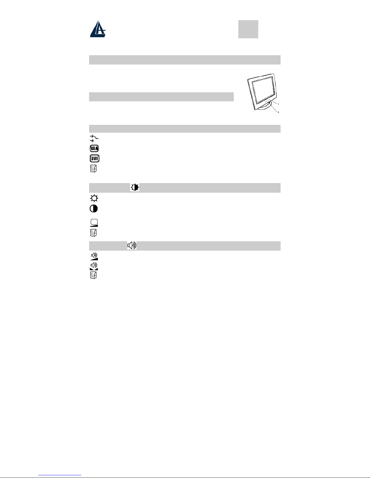
1 Getting Started
Congratulations on your purchase of a TFT LCD Color Monitor. This section lists package contents,
features, precautions, as well as cleaning and installation instructions.
IMPORTANT!PLEASE KEEP THE ORIGINAL BOX AND ALL PACKING MATERIAL FOR FUTURE SHIPPING
NEEDS.
1.1 Precautions
•Sit at least 18"(45 cm) away from the screen when in use.
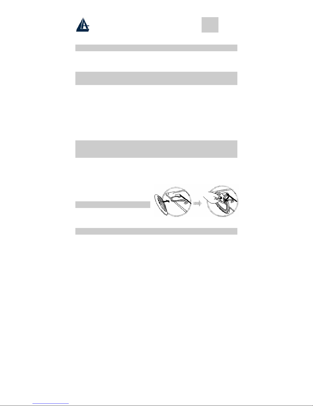
•Do not touch the LCD panel with your bare hands. Oil from your skin is difficult to remove and
may damage the screen.
•Do not expose the LCD monitor directly under sunlight or other heat sources. When in use, the
LCD screen should be facing away from light sources to reduce glare.
•It is important to choose a well-ventilated area to place your LCD monitor for adequate ventilation.
Do not place anything on top of the LCD monitor.
•Ensure the area around the LCD monitor is clean and moisture-free.
•Do not place heavy objects on the power cord, adapter, or signal cables.
•If smoke, abnormal noise, or strange odor occurs, immediately turn the LCD monitor off and call
your dealer. Do not continue using the LCD monitor.
•Do not remove the rear cover by yourself. The display unit contains high-voltage parts and may
expose you to the electric shock. Contact your local dealer if service is needed.

ENGLISH
A05-17AM-D01 - A05-17BM-D03 - A05-19BM-D02_X02 6 - 40
•When moving, always handle your LCD monitor with care.
•Do not forcefully press down against the LCD display as this will damage the monitor.
1.2 Cleaning the TFT LCD Monitor
•Wipe the screen gently with a clean camel hairbrush, or a soft, clean, lint-free cloth.
Removing the dust and other particles will prevent your LCD panel from being scratched.
•Never pour or spray any liquid onto the LCD monitor
•Do not apply pressure to the LCD panel.
1.3 Federal Communications Commission (FCC)
Statement
This Equipment has been tested and found to comply with the limits for a class B digital device, pursuant to
Part 15 of the FCC rules. These limits are designed to provide reasonable protection against harmful
interference in a residential installation. This equipment generates, uses and can radiate radio frequency
energy and, if not installed and used in accordance with the instructions, may cause harmful interference to
radio communications. However, there is no guarantee that interference will not occur in a particular
installation. If this equipment does cause harmful interference to radio or television reception, which can be
determined by turning the equipment off and on, the user is encouraged to try to correct the interference by
one or more of the following measures:
•Reorient or relocate the receiving antenna.
•Increase the separation between the equipment and receiver.
•Connect the equipment into an outlet on a circuit different from that to which the receiver is
connected. - Consult the dealer or an experienced radio/TV technician for help.
2 Installing the Monitor
2.1 Unpacking
Open the shipping cartons and check the contents.
If any items are missing or damaged, contact your dealer immediately.
The package should include the following items:
•TFT color monitor
•User's guide
•Power cord
•Signal cable
•DC power adapter
•Audio cable
2.2 Installing the Base
Follow these steps to install the base:
1. Turn the monitor down.
2. Assembly the base to the arm with screw.
3. Tie the screw with a coin.
2.3 Installing the Monitor
This monitor is equipped with an auto sensing DC power adapter for voltage ranges 100-240VAC, 60/50Hz.
Confirm the line voltage designation on the rear panel of the monitor. Follow these steps to install the
monitor:
1. Before you connect the cables, made sure that the monitor and the system uni power switches
are off.
2. Plug one end of the 15pin-signal cable to the monitor and the other end to the video signal
connector at the rear of the system. Tighten the two screws on the cable connector.

ENGLISH
A05-17AM-D01 - A05-17BM-D03 - A05-19BM-D02_X02 7 - 40
3. Connect the DC power cord to the DC jack.
4. Connect the power cable.
3 Control Functions
The monitor digital control functions are located on the front panel. They are shown in the figure below
and described in the following paragraphs.
1. Power Switch with Indicator LED
2. Function Keys
4 Function Select
With the Uand Vknobs, you can adjust the speakers volume.
Press the 1 knob to show the OSD menu. Than use the Uand Vknobs to select
a function. Press the 2 knob to close the OSD menu. You can hold the 2 knob for
more than 3 second to adjust the image quality automatically.
4.1 Input Select (not for A05-17AM-D01)
Input Select
VGA signal Select the image signal coming from the VGA cable.
DVI signal Select the image signal coming from DVI cable. (option)
Exit Close the Signal Select OSD menu.
4.2 Video
Brightness Adjust the luminance level in the image.
Contrast Adjust the difference in luminance between light and dark areas of the
image.
Black Level Adjust the black Level in the image.
Exit Close the Video OSD menu.
4.3 Audio
Volume Adjust the volume of speakers
Balance Adjust the speaker’s volume to right side or left side.
Exit Close the Audio OSD menu

ENGLISH
A05-17AM-D01 - A05-17BM-D03 - A05-19BM-D02_X02 8 - 40
4.4 Color
4.4.1 Color Temperature
User Adjust the R.G.B. gain level.
6500K Select color temperature to 6500°K.
9300K Select color temperature to 9300°K.
Exit Close the Color Temperature OSD menu.
4.4.2 Adjust the flesh tone of the image
Shade Adjust the shade of the image color.
Saturation Adjust the saturation of the image color.
Exit Close the Color OSD menu.
4.4.3 Image Adjust
Geometry Adjust geometry of the image automatically.
Horizontal size Adjust the horizontal sync size of signal.
Horizontal phase Adjust the horizontal sync phase of signal.
Horizontal position Adjust the horizontal position of the image.
Vertical position Adjust the vertical position of the image.
Exit Close the Image OSD menu
4.5 Language
Sets the language of the OSD windows.
4.6 Tools
4.6.1 OSD Controls
Display time Setting the OSD menu display time.
OSD H. Position OSD H. Position Adjust the horizontal position of the OSD menu.
OSD V. Position OSD V. Position Adjust the vertical position of the OSD menu.
Exit Close the OSD Control OSD menu

ENGLISH
A05-17AM-D01 - A05-17BM-D03 - A05-19BM-D02_X02 9 - 40
4.6.2 Recall the factory default setting
4.6.3 Sharpness
Adjust the picture display more clear
Exit Close the Tools OSD menu
Exit Close the OSD menu
5 Micro-controller Features
The micro-controller automatically detects the video board installed in your system. When you turn on the
monitor, the micro-controller first checks the display mode memory stored in the user setting area of the
video board, and then the factory presetting area. It then adjusts to the proper display mode.
6 Display Modes Memory
The micro-controller has the memory capacity to store different display modes, including timing formats and
display-settings. This memory capacity is divided into two parts: the user setting area and the factory
presetting area.
6.1 User Setting Area
The user setting area on the micro-controller maintains in its memory the last display modes set by the
user. You can change the settings, or add a nonstandard mode. The micro-controller always detects and
displays the last mode stored in the user setting area first when the monitor is turned on.
6.2 Factory Presetting Area
There are some preferred display modes preset in the micro-controller. These display modes are preset
at the factory and include the most popular display modes currently available. The micro-controller
searches for a proper display mode in this area if it fails to find a proper display mode in the user setting
area.
MODE Resolution
(Dots*lines)
Horizontal
Freq. (KHz)
Vertical
Freq. (Hz) Remark
1. VGA 640×350 31.5 70 Non-interlaced
2. VGA 720×400 31.5 70 Non-interlaced
3. VGA 640×480 31.5 60 Non-interlaced
4. VESA/75 640×480 37.5 75 Non-interlaced
5. VESA/60 800×600 37.9 60 Non-interlaced
6. VESA/75 800×600 46.9 75 Non-interlaced
7. VESA/60 1024×768 48.4 60 Non-interlaced
8. VESA/70 1024×768 56.5 70 Non-interlaced
9. VESA/75 1024×768 60.0 75 Non-interlaced
10. VESA/60 1280×1024 64.0 60 Non-interlaced
11. VESA/75 1280×1024 80.0 75 Non-interlaced
7 Signal Connector Pin-outs
To connect VGA, 8514A or IBM-compatible graphics adapters, use a 15 pin mini D-type male connector.

ENGLISH
A05-17AM-D01 - A05-17BM-D03 - A05-19BM-D02_X02 10 - 40
7.1 15-pin Mini D-type Male VGA Connector
1 Red Video 6 Red Ground 11 Ground
2 Green Video 7 Green Ground 12 Serial Data/I/O
3 Blue Video 8 Blue Ground 13 H. Sync
4 Ground 9 No Connection 14 V. Sync
5 No Connection 10 Sync Ground 15 Serial Clock Input
8 Power Saving Feature
When the power saving active them the power indicator LED will be from Green Light to Amber, And
power saving feature complies with these VESA power saving modes:
Mode H. Sync. V. Sync. LED Power Consumption
Normal On On Green
<40W A05-17AM-D01
A05-17BM.D03 <45W
A05-19BM-D02
Stand-by Off On Amber <3W
Suspend On Off Amber < 3W
Off Off Off Amber < 3W
The monitor uses the H. Sync and V. Sync signals to determine the operation mode to enter.
The monitor power-saving feature automatically turns off H. Sync and V. Sync if there is no input from the
system for a certain period of time. To use this feature, you need a green PC that is compliant with the
VESA power saving feature or a software utility to detect system input such as keyboard or mouse.
9 Time Settings
Time settings are adjusted from the system unit by software. To fulfill the requirements in the NUTEK
specification 803299/94 the total time from indicated inactivity to Power Saving position A2 (VESA OFF)
must not be set more than 70 minutes. We recommend you switch off the monitor when you do not intend to
use it for awhile.
10 Specifications
A05-17AM-D01
A05-17BM.D03 17.0" (full 17.0" viewable diagonal area)
Size
A05-19BM-D02 19.0" (full 17.0" viewable diagonal area)
Type TFT (Thin Film Transistor), Active Matrix Panel
Pixel Pitch A05-17AM-D01
A05-17BM.D03 0,264mm
A05-19BM-D02 0,294mm
Color 16.7M
Glass surface Anti-Glare & Hard Coat 3H
Brightness 250 cd/m2
A05-17AM-D01
A05-17BM.D03 500:1
Contrast
A05-19BM-D02 600:1
View Angle 170 H - 170 V
A05-17AM-D01
A05-17BM.D03 337.92x270.336 mm
LCD
Full screen
A05-19BM-D02 376.320X301.056 mm

ENGLISH
A05-17AM-D01 - A05-17BM-D03 - A05-19BM-D02_X02 11 - 40
Resolution Primary Mode 1280x1024 @75Hz (Max.)
RGB Analog
Input Signal Video DVI Digital (not for A05-17AM-D03)
Connectors D-sub 15 pin
Input Signal DVI-D (not for A05-17AM-D03)
Sync H. V., Separate Sync,
TTL Compatible
Horizontal Frequency 31-80kHz,
Vertical Frequency 50-75Hz,
Video Sync
Video Bandwidth 80MHz
Input Stereo mini- Audio Line-in
Audio Speakers 3W x 2 (At 1KHz for THD 1% Amplifier)
Power Voltage 220V - 12V / 4.2A
Temperature 0°C to 40°C
Operating
Conditions Humidity 10-90% (non-condensing)
Temperature 0to 60Storage
Conditions Humidity 10-90% (non-condensing)
Physical 425mm (L) x 175mm (W) x 425mm (H)
Dimensions Package 490mm (L) x 155mm (W) x 500mm (H)mm
A05-17AM-D01
A05-17BM.D03 5.5 Kg
Net
A05-19BM-D02 6,0 Kg
A05-17AM-D01
A05-17BM.D03 7.0 Kg
Weight
Gross
A05-19BM-D02 7,5 Kg
Safety UL/CUL, TUV/GS, CE, CB, FCC-B
Energy Star EPA
Regulations
Quality ISO 13404-2 Class II
A05-17AM-D01
A05-17BM.D03 <42W
On
A05-19BM-D02 <45W
Power saving
Off <3W


ITALIANO
A05-17AM-D01 - A05-17BM-D03 – A05-19BM-D02_X02
Avvertenze
•Leggere attentamente queste informazioni e tenerle disponibili per una eventuale consultazione
successiva.
•Tenere presente anche tutte le indicazioni riportate sul prodotto.
•Staccare ogni collegamento elettrico quando viene effettuata la pulizia. Non usare mai liquidi o un
detergente a spruzzo, usare sempre un panno leggermente umido.
•Consultare quanto riportato a pagina 14 Pulizia del pannello LCD, per ulteriori dettagli
•Mantenere sempre il monitor fuori da aree con alta percentuale di umidità.
•Mantenere il prodotto in posizione stabile. L’eventuale caduta potrebbe causare un
danneggiamento serio.
•Non chiudere le aperture presenti sul monitor, servono per la ventilazione. Non installare il monitor
in aree poco ventilate e mantenerlo sempre lontano da fonti di calore.
•Il cavo di alimentazione utilizzato deve essere quello fornito col prodotto. Chieda al suo rivenditore
in caso di eventuali dubbi.
•Il cavo è provvisto del filo di terra onde evitare scariche elettriche. Non utilizzare cavi di
alimentazione sprovvisti della connessione di terra.
•Non porre il cavo di alimentazione in luoghi di passaggio, e non mettere nulla di pesante sopra.
•Non inserire oggetti o versare liquidi tramite le aperture. Sono presenti all’interno aree di alta
tensione che potrebbero causare scosse elettriche o corto circuiti.
•Non cercare di riparare da solo il monitor.
•Contattare il nostro centro di assistenza.
•Non toccare il cavo di alimentazione nelle situazioni qui indicate, ma chiamare un elettricista
esperto:
•Quando il cavo di alimentazione è danneggiato o tagliato
•Se del liquido è stato versato nel monitor
•Se il prodotto è stato esposto alla pioggia o ad elevata umidità
•Se il prodotto non può essere tarato e settato tramite le normali procedure di installazione.
Eventuali tarature ulteriori devono essere effettuate da un centro specializzato.
•Se il monitor è stato aperto o rotto.
•Se si evidenziano rilevanti modifiche nel funzionamento.
•Utilizzare il cavo di alimentazione a corredo per un utilizzo sicuro e per evitare incidenti.
11 Prima di iniziare
Congratulazioni per il Suo acquisto di questo monitor LCD. Legga attentamente questa sezione del
manuale per una rapida conoscenza del prodotto e delle operazioni da effettuare correttamente.
IMPORTANTE: CONSERVI LA SCATOLA DELL’IMBALLO E TUTTO IL MATERIALE
DELL’IMBALLO,POTREBBE SERVIRE PER EVENTUALI FUTURE SPEDIZIONI.
11.1 Precauzioni
•Tenersi ad almeno 45 cm di distanza dal pannello durante l’uso.
•Non fare pressioni sul pannello: è fragile
•Non toccare il pannello con le mani sporche. L’unto della pelle risulta di difficile rimozione.
•Non esporre direttamente il pannello alla luce solare o ad altre fonti di calore.
•Durante l’utilizzo, non indirizzare luci dirette sul pannello, per evitare fastidiosi riflessi.
•È importante scegliere un posto ben ventilato dove posizionare il monitor. Non porre nulla sopra il
monitor.
•In presenza di fumo, rumori strani, o odori particolari, spegnere immediatamente il monitor e
chiamare il centro assistenza. Non continuare comunque ad utilizzare il monitor.

ITALIANO
A05-17AM-D01 - A05-17BM-D03 – A05-19BM-D02_X02
•Non rimuovere il guscio posteriore. Il monitor contiene un’area ad alta tensione e si corre il rischio
di ricevere una forte scarica elettrica. Contattare il centro di assistenza per ogni necessità.
•Se è necessario muovere il monitor, usare sempre attenzione.
•Non fare pressioni sul pannello LCD in caso di malfunzionamenti. Fare riferimento alla pagina 15
per eventuali tarature.
11.2 Pulizia del pannello LCD
•Utilizzare un pennello in pelo di cammello per lenti o un panno soffice, pulito e non peloso, per
togliere dal pannello tracce di polvere e di ogni altra impurità; strofinare leggermente per non rigare
il pannello.
•Se qualche impurità permane, inumidire leggermente il panno ripetere l’operazione.
•Non versare mai e neppure spruzzare liquidi sul pannello.
NON PREMERE MAI SUL PANNELLO.
11.3 Comunicato relativo alle interferenze Radio
Questa apparecchiatura è stata esaminata e giudicata conforme ai limiti per le apparecchiature digitali della
Classe B, rispettando la parte 15 delle Regole FCC.
Questi limiti sono stati definiti per provvedere ragionevoli protezioni contro le interferenze in installazioni di
tipo residenziale. Questa apparecchiatura genera, usa e può irradiare onde elettromagnetiche, se non è
installato ed utilizzato in accordo con le istruzioni, può causare interferenze percepibili alle comunicazioni
radio. Comunque non esiste garanzia che nessuna interferenza possa mai accadere in installazioni
particolari.
Se questa apparecchiatura dovesse creare interferenze a radio o televisori, durante la fase di accensione o
spegnimento, l’utente è invitato a correggere le interferenze tramite una delle seguenti modalità:
•Riorientare o riposizionare l’antenna ricevente
•Aumentare la distanza tra questa apparecchiatura ed il ricevitore
•Alimentare l’apparecchiatura da una presa diversa rispetto a quella alla quale sia collegata il
ricevitore.
•Consultare il rivenditore o un esperto tecnico radio/TV per un aiuto.
11.3.1FCC Avvertimento
Per assicurare la continuità del rispetto delle normative FCC, l’utilizzatore deve assicurare un corretto
collegamento di terra al cavo di alimentazione, assicurarsi che il cavo di collegamento video sia schermato
con una opportuna maglia di ferrite.
Inoltre, ogni cambio o modifica non autorizzata di questo monitor LCD potrebbero invalidare il diritto
dell’utente di utilizzare questa apparecchiatura.
11.4 Precauzioni per il cavo di alimentazione
Utilizzare un cavo fornito di corretto collegamento a terra.
12 Installazione del monitor
12.1 Disimballo
Aprire la confezione e controllarne il contenuto.
Se vi sono componenti mancanti o danneggiati, rivolgersi immediatamente il rivenditore.
La confezione deve includere i seguenti elementi:
•Monitor a colori TFT
•Guida dell'utente
•Cavo di alimentazione
•Cavo del segnale
•Alimentatore CC

ITALIANO
A05-17AM-D01 - A05-17BM-D03 – A05-19BM-D02_X02
•Cavo Audio
12.2 Installare la base
Segua questi passi per installare la base:
3. Capovolgere il monitor.
4. Fissare la base al braccio con la vite.
5. Stringere la vite con una moneta.
12.3 Installazione del
monitor
Questo monitor è dotato di un alimentatore DC che
funziona con una tensione che deve essere compresa tra 100-240VAC 60/50Hz. Verificare la tensione
indicata sul pannello posteriore del monitor. Per installare il monitor eseguire le operazioni seguenti:
1. Prima di collegare i cavi, assicurarsi che gli interruttori dell’alimentazione del monitor e del
personal computer siano spenti.
2. Inserire un connettore del cavo del segnale a 15 pin nel monitor e l’altra estremità alla
scheda video sul retro del sistema. Stringere le due viti sul connettore.
3. Connettere il cavo di alimentazione DC al jack DC.
4. Connettere il cavo di alimentazione.
13 Funzioni di Controllo
Le funzioni di controllo digitali del monitor si trovano sul pannello anteriore. Sono indicate
nella figura riportata sotto e descritte nei paragrafi che seguono.
14 Selezione della funzione
Premere il tasto 1 per visualizzare il menu OSD, quindi usare i tasti e per
selezionare una funzione.
Con i tasti e , è possibile regolare il volume degli altoparlanti. Premere il tasto
2 per chiudere il menu OSD
Per regolare automaticamente la qualità dell’immagine tenere premuto per un
periodo superiore a 3 secondi il tasto 2.
Il menu OSD viene chiuso automaticamente dopo 3-5 secondi di inattività
salvando le eventuali modifiche effettuate.
14.1 Selezione ingresso (non per A05-17AM-D01)
Selezione ingresso
Segnale VGA Seleziona l’ingresso video dal connettore VGA.
Segnale DVI Seleziona l’ingresso video dal connettore DVI.(Non
disponibile nel modello A05-17AM-D01)
Uscita Termina la funzione selezione ingresso.
14.2 Video
Luminosità Regola la luminosità dell’immagine

ITALIANO
A05-17AM-D01 - A05-17BM-D03 – A05-19BM-D02_X02
Contrasto Regola la differenza tra le aree luminose e quelle scure dell’immagine
Livello del nero Regola il livello del nero.
Exit Per terminare le regolazioni dello schermo
14.3 Audio
Volume Regola il volume degli altoparlanti
Bilanciamento Regola il bilianciamento del segnale tra destra e sinistra
Exit Per terminare le regolazioni audio
14.4 Colore
14.4.1Temperatura Colore
User Regola i livelli di Rosso, Blu e Verde
6500K Posiziona la temperatura colore a 6500°K.
9300K Posiziona la temperatura colore a 9300°K.
Exit Per terminare le regolazioni della temperatura Colore
14.4.2Regolazione del tono dell’immagine
Sfumatura Regola le sfumature del colore
Saturazione Regola la saturazione dei colori
Exit Termina la regolazione del tono
14.4.3Regolazione Immagine
Geometria Regola automaticamente la geometria dell’immagine.
Grandezza Regola la grandezza orizzontale dell’immagine
Fase Regola la fase
Posizione orizzontale Regola la posizione orizzontale dell’immagine
Posizione verticale Regola la posizione Verticale dell’immagine
Exit Close the Image OSD menu

ITALIANO
A05-17AM-D01 - A05-17BM-D03 – A05-19BM-D02_X02
14.5 Lingua
Seleziona la lingua del menu.
14.6 Strumenti vari
14.6.1Controlli OSD
Temporizzazione Regola il tempo di visualizzazione dell’OSD
Pos. Orizzontale Controlla il posizionamento orizzontale dell’OSD
Pos. Verticale Controlla il posizionamento verticale dell’OSD
Exit Chiude la regolazione dell’OSD
14.6.2Richiama le regolazioni di fabbrica
14.6.3Regolazione fine
Permette una regolazione più raffinata dell’immagine
Exit Chiude la funzione strumenti
Exit Chiude la finestra OSD
15 Caratteristiche Microprocessore
Il Microprocessore riconosce automaticamente la scheda video installata nel sistema. Quando si
accende il monitor, il microprocessore per prima cosa controlla il tipo di monitor memorizzato nelle
impostazioni dell’utente della scheda video, quindi le impostazioni di fabbrica. Infine viene regolata
l’impostazione corretta.
16 Memoria Modalità Schermo
Il Microprocessore memorizza diverse modalità di visualizzazione, oltre al formato di sincronizzazione e
alle impostazioni dello schermo. Questa memoria è divisa in due aree: l’area delle impostazioni
dell’utente e l’area delle impostazioni di fabbrica.
16.1 Area Impostazioni dell’Utente
L’area delle impostazioni dell’utente sul Microprocessore mantiene in memoria le ultime modalità di
schermo impostate dall’utente. È possibile cambiare le impostazioni o aggiungere una nuova modalità.
Il Microprocessore riconosce e visualizza sempre l’ultima modalità memorizzata nell’area delle
impostazioni dell’utente quando il monitor viene acceso.
16.2 Area Impostazioni di Fabbrica
Sono presenti sul Microprocessore alcune modalità di schermo più frequentemente utilizzate. Queste
modalità di schermo sono già impostate dalla fabbrica e includono le più comuni modalità attualmente
disponibili. Il Microprocessore cerca la modalità più corretta in questa area, qualora non sia stata trovata
una modalità accettabile nell’area delle impostazioni dell’utente.

ITALIANO
A05-17AM-D01 - A05-17BM-D03 – A05-19BM-D02_X02
Modalità Risoluz.
(punti x linee)
Freq.Orizz.
(KHz)
Freq.Vert.
(Hz) Note
1 VGA 640x350 31.5 70 Non interlacc.
2 VGA 720x400 31.5 70 Non interlacc.
3 VGA 640x480 31.5 60 Non interlacc.
4 VESA/75 640x480 37.5 75 Non interlacc.
5 VESA/60 800x600 37.9 60 Non interlacc.
6 VESA/75 800x600 46.9 75 Non interlacc.
7 VESA/60 1024x768 48.4 60 Non interlacc.
8 VESA/70 1024x768 56.5 70 Non interlacc.
9 VESA/75 1024x768 60.0 75 Non interlacc.
10 VESA/60 1280x1024 64.0 60 Non interlacc.
11 VESA/75 1280x1024 80.0 75 Non interlacc.
17 Piedinatura del cavo segnale VGA
Per collegare adattatori grafici VGA, 8514A o IBM compatibili, utilizzate un mini cavo maschio di tipo D a
15 pin.
1 Video Rosso 6 Rosso Terra 11 Terra
2 Video Verde 7 Verde Terra
Gd
12 Data/I/O
3 Video Blu 8 Blu Terra 13 Sincro Orizz.
4 Terra 9 Non utilizzato 14 Sincro Vert.
5 Non utilizzato 10 Sync Terra 15 Ingresso Clock
18 Funzioni per il risparmio energetico
Quando si attiva la funzione di risparmio energetico, l’indicatore LED di alimentazione passerà da verde
a rosso. La funzione di risparmio energetico si configura secondo le seguenti modalità VESA:
Modalità Sincroniz.
Orizz.
Sincroniz.
Vert. LED Consumo energetico
Normale Acceso Acceso Verde < 40 W A05-17AM-D01
A05-17BM.D03 < 45 W
A05-19BM-D02
Stand-by Spento Acceso Rosso < 3 W < 3 W
Sospeso Acceso Spento Rosso < 3 W < 3 W
Spento Spento Spento Rosso < 3 W < 3 W
Il monitor utilizza i segnali di sincronizzazione orizzontale e verticale per decidere in quale modalità entrare.
La funzione di risparmio energetico del monitor spegne automaticamente la sincronizzazione orizzontale e
verticale se non vi è alcun segnale proveniente dal computer per un periodo. Per utilizzare questa funzione,
vi serve un PC verde omologato alle funzioni di risparmio energetico VESA o un programma per rilevare
segnali provenienti dal computer, per esempio dalla tastiera o dal mouse.
19 Regolazione del tempo
La regolazione del tempo viene operata dal programma che sta girando nel computer. Per soddisfare i
requisiti menzionati nel NUTEK 803299/94, il tempo totale di inattività prima di entrare nella funzione di
risparmio energetico A2(VESA spento) non deve essere regolato a più di 70 minuti. Vi raccomandiamo
di spegnere il monitor quando avete intenzione di non utilizzarlo per un po’ di tempo.

ITALIANO
A05-17AM-D01 - A05-17BM-D03 – A05-19BM-D02_X02
20 Specifiche
A05-17AM-D01
A05-17BM.D03 17.0" (full 17.0" viewable diagonal area)
Dimensioni
A05-19BM-D02 19.0" (full 17.0" viewable diagonal area)
Tipo TFT (Thin Film Transistor), Active Matrix Panel
A05-17AM-D01
A05-17BM.D03 0,264mm
Pixel Pitch
A05-19BM-D02 0,294mm
Colori 16.7M
Trattamento superficie Anti-Glare & Hard Coat 3H
Luminosità 250 cd/m2
A05-17AM-D01
A05-17BM.D03 500:1
Contrasto
A05-19BM-D02 600:1
Angolo Visuale 170 H - 170 V
A05-17AM-D01
A05-17BM.D03 337.92x270.336
LCD
Area Visibile
A05-19BM-D02 376.320X301.056 mm
Risoluzione Primaria 1280x1024 @75Hz (Max.)
RGB Analogico
Segnale ingresso Video DVI Digitale (non per A05-17AM-D01)
Sync H. V., Separate Sync,
TTL Compatibile
Frequenza Orizzontale 31-80kHz,
Frequenza Verticale 50-75Hz,
Video Sync
Banda Passante 80MHz
D-sub 15 pin
Connettore Input Signal DVI-D (non per A05-17AM-D01)
Input Stereo mini- Audio Line-in
Audio Altoparlanti 3W x 2 (At 1KHz for THD 1% Amplifier)
Alimentazione 220 V 12V / 4.2A
Temperatura 0°C to 40°C
Condizioni di utilizzo Umidità 10-90% (senza condensa)
Temperatura 0a 60
Condizioni di imballo Umidità 10-90% (senza condensa)
Prodotto 425mm (L) x 175mm (W) x 425mm (H)
Dimensioni Imballo 490mm (L) x 155mm (W) x 500mm (H)mm
A05-17AM-D01
A05-17BM.D03 5.5Kgs
Netto:
A05-19BM-D02 6,0 Kg
A05-17AM-D01
A05-17BM.D03 7.0Kg
Peso
Lordo:
A05-19BM-D02 7,5 Kg
Sicurezza UL/CUL, TUV/GS, CE, CB, FCC-B
Energy Star EPA
Normative
Qualità ISO 13404-2 Class II

ITALIANO
A05-17AM-D01 - A05-17BM-D03 – A05-19BM-D02_X02
A05-17AM-D01
A05-17BM.D03 <42W
On
A05-19BM-D02 <45W
Risparmio
Energetico
Off <3W
This manual suits for next models
2
Table of contents
Languages:
Other Atlantis Land Monitor manuals

Atlantis Land
Atlantis Land I-See S 172 User manual

Atlantis Land
Atlantis Land A05-17AM-L02 User manual

Atlantis Land
Atlantis Land LCD 17" Monitor A05-17AM-C08 User manual

Atlantis Land
Atlantis Land A05-15AM-L01 User manual

Atlantis Land
Atlantis Land A05-17AM-L03 User manual

Atlantis Land
Atlantis Land I-See S170 17" LCD Monitor A05-17AM-C02 User manual

Atlantis Land
Atlantis Land A05-19BM-F02 User manual

Atlantis Land
Atlantis Land I-See S150 LCD Monitor A05-15AM-C01 User manual

Atlantis Land
Atlantis Land I-SEE H191 User manual

Atlantis Land
Atlantis Land I-See S 173 User manual