Any revisions must first be approved by the product designer. Version: 201710 Revision By: TD
12. ADJUSTING
BLOCK
Apply the plastic
grommets into the
holes in the glass
panel HZ-F.
Assemble retainer
plate as shown.
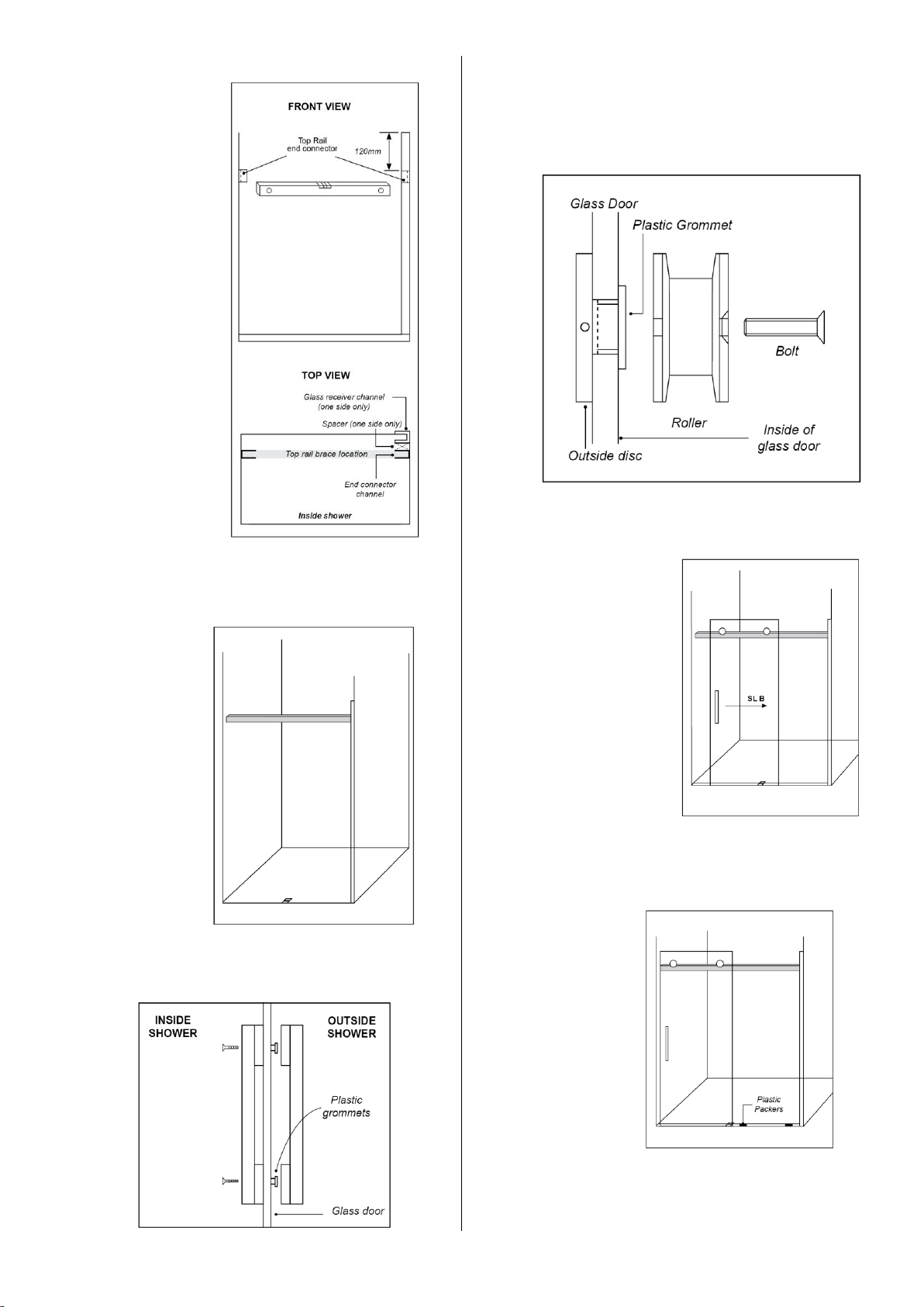
13. ROLLER SET ASSEMBLY TO GLASS DOOR
Ensure the
direction of the
door is correct.
Fit the plastic
grommet
through the
glass first (note
direction of
grommet).
Tighten with
the 4mm hex
key supplied.
14. HANDLE INSTALLATION
Assemble
handles as
shown. Use
3mm Hex
Key
supplied
with handle
set.
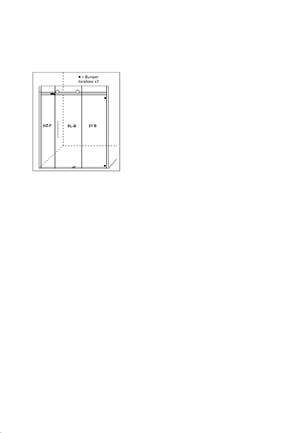
15. DOOR INSTALLATION
Protect the top rail brace outside face with the
blue tape
supplied. Stand
outside the
shower.
Lift the door,
SL-B and place
rollers onto the
top rail brace.
At the same
time locate the
door into the bottom door guide. Adjust the
door height and alignment by loosening the
roller bolt and rotating the outside disc. Ensure
the bottom of the door clears the floor tiles.
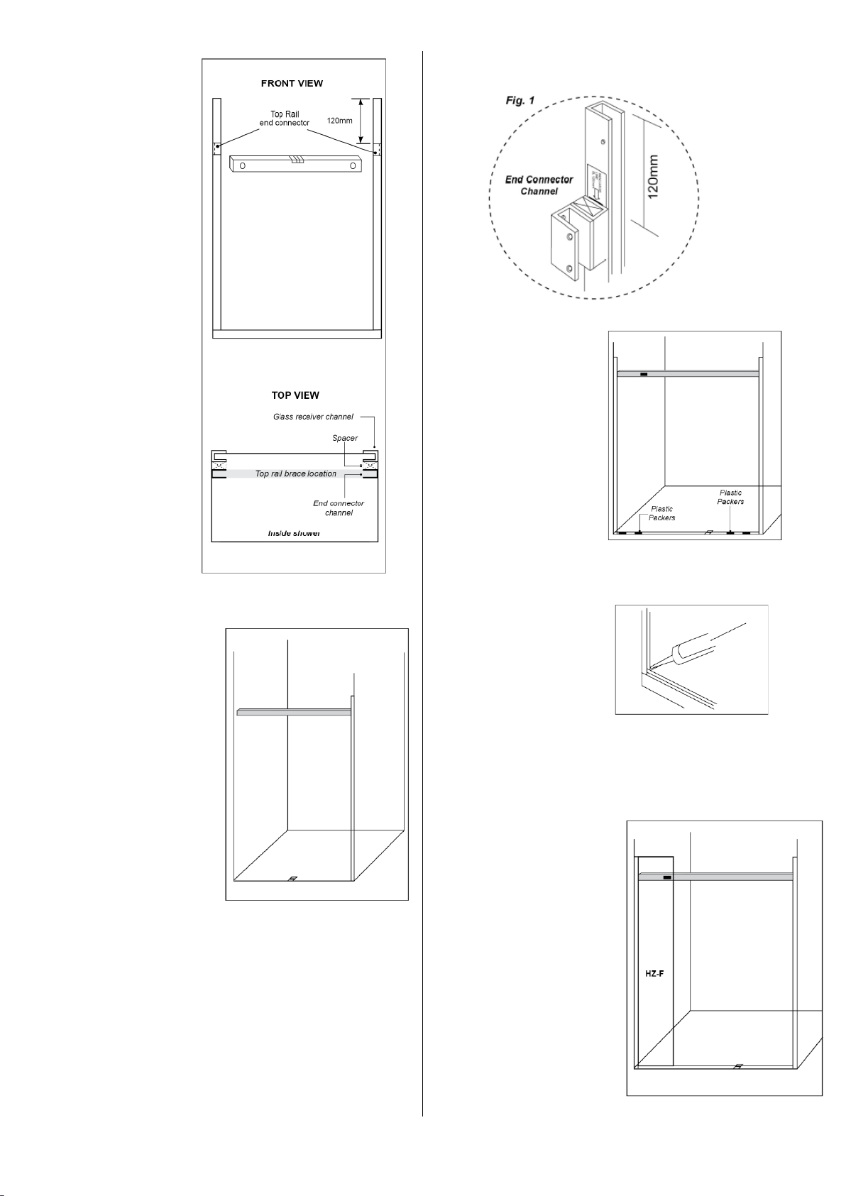
16. INSTALLATION OF FIXED PANEL
Remove dust and dirt first. Seal the connection
between the glass receiver channel and the base
glazing channel with clear silicon, prior to the
installation of panel 21 B.
Locate the glass panel 21 B into the glazing
channel. Add or remove packers in the base
glazing channel as necessary.
17. SILL INFILL
Trim Sill Infill to suit. Apply a continuous dead of
clear silicon to each inside face of the base
channel. Ensure the ends of the Sill Infill are
sealed and place into the base channel in the
location as shown.
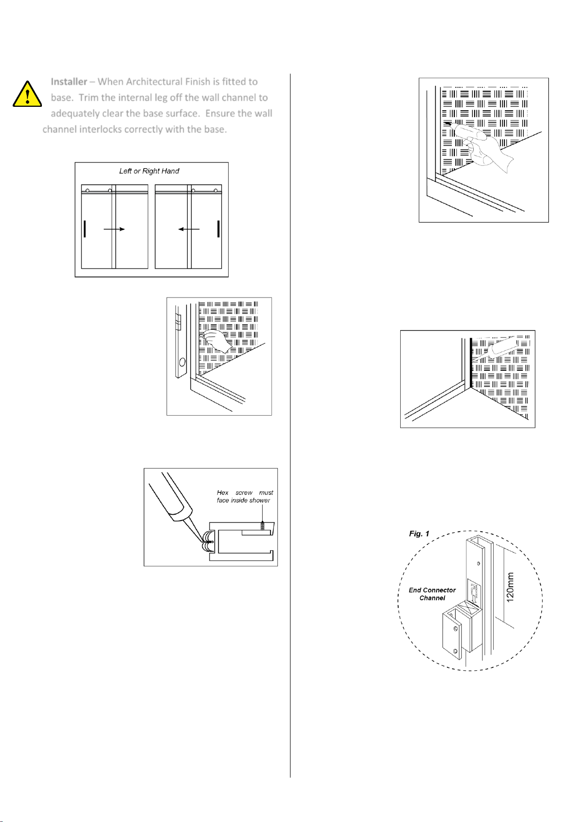
18. FASTENING GLASS
Secure the glass panels into the receiver
channels by tightening hex screws firmly with
hex key supplied.
19. ADJUSTING BLOCK COVERS
Add or remove
spacers behind the
adjusting block for
satisfactory door
alignment. Apply
clear silicon to the
heads of the
screws and place
cover plate over end retainer plate. Tape in place
for 24 hours.
20. SILICON APPLICATION
Using the blue tape supplied, mask the glazing
channels and glass at the intersections as
shown. Apply clear silicon to the inside and
outside of the glass panels. Use the spatula
provided to remove the excess silicon. Remove
the masking tape immediately after application.