Atlas Copco FD90 User manual

Atlas Copco Air dryers
No. 2920 1390 02
Replaces No. 2920 1390 01
Registration code: APC FD / 38 / 975
2001-12
FD90, FD110, FD130, FD170 and FD230
Instruction book
Web-site: ttp://www.atlascopco-compressors.com
·
Copyrig t 2001, Atlas Copco Airpower n.v., Antwerp, Belgium.
Any unaut orized use or copying of t e contents or any part t ereof is pro ibited. T is
applies in particular to trademarks, model denominations, part numbers and drawings.
·
T is instruction book meets t e requirements for instructions specified by t e mac inery
directive 98/37/EC and is valid for CE as well as non-CE labelled mac ines.

2920 1390 02
2
Instruction book
T is instruction book describes ow to andle and operate t e subject mac ine(s) to ensure safe operation, optimum working
economy and long service life.
Read this book before putting the machine into operation to ensure correct andling, operation and proper maintenance from
t e beginning. T e maintenance sc edule contains a summary of t e measures for keeping t e dryer in good repair. T e
maintenance procedures are simple but must be carried out regularly.
Keep t e book available for t e operator(s) and make sure t at t e dryer is operated and t at t e maintenance actions are carried
out according to t e instructions. Record all operating data, maintenance work effected, etc. in an operator's logbook available
from Atlas Copco. Follow all applicable safety precautions, amongst ot ers t ose mentioned in t is book.
Repair operations s ould be performed by trained personnel from Atlas Copco w o can also be contacted if any furt er information
is desired.
In all correspondence always mention t e dryer type and t e complete serial number, s own on t e data plate.
For all specific data not mentioned in t e text, consult sections "Maintenance" and "Principal data".
The company reserves the right to make changes ithout prior notice.
Page
3.2 Starting . . . . . . . . . . . . . . . . . . . . . . . . . . . . . . . . . 13
3.3 During operation . . . . . . . . . . . . . . . . . . . . . . . . . . 14
3.4 Stopping . . . . . . . . . . . . . . . . . . . . . . . . . . . . . . . . 14
4 Maintenance . . . . . . . . . . . . . . . . . . . . . . . . . . . . . . . . 14
5 Settings . . . . . . . . . . . . . . . . . . . . . . . . . . . . . . . . . . . . . 14
6 Problem solving. . . . . . . . . . . . . . . . . . . . . . . . . . . . . . 14
7 Principal data . . . . . . . . . . . . . . . . . . . . . . . . . . . . . . . 15
7.1 Limitations/nominal conditions . . . . . . . . . . . . . . 15
7.2 Specific data of FD90, FD110 and FD130. . . . . . 15
7.3 Specific data of FD170 and FD230 . . . . . . . . . . . 16
8 Conversion list of SI units into British units . . . . . . 16
Contents
Page
1 Leading particulars . . . . . . . . . . . . . . . . . . . . . . . . . . . 3
1.1 General description . . . . . . . . . . . . . . . . . . . . . . . . . 3
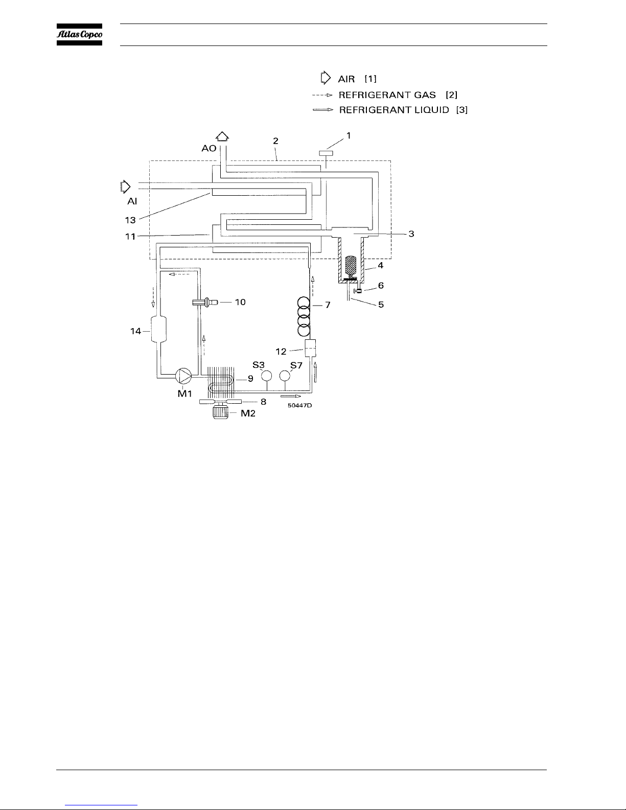
1.2 Air circuit . . . . . . . . . . . . . . . . . . . . . . . . . . . . . . . . 3
1.3 Refrigeration circuit . . . . . . . . . . . . . . . . . . . . . . . . 3
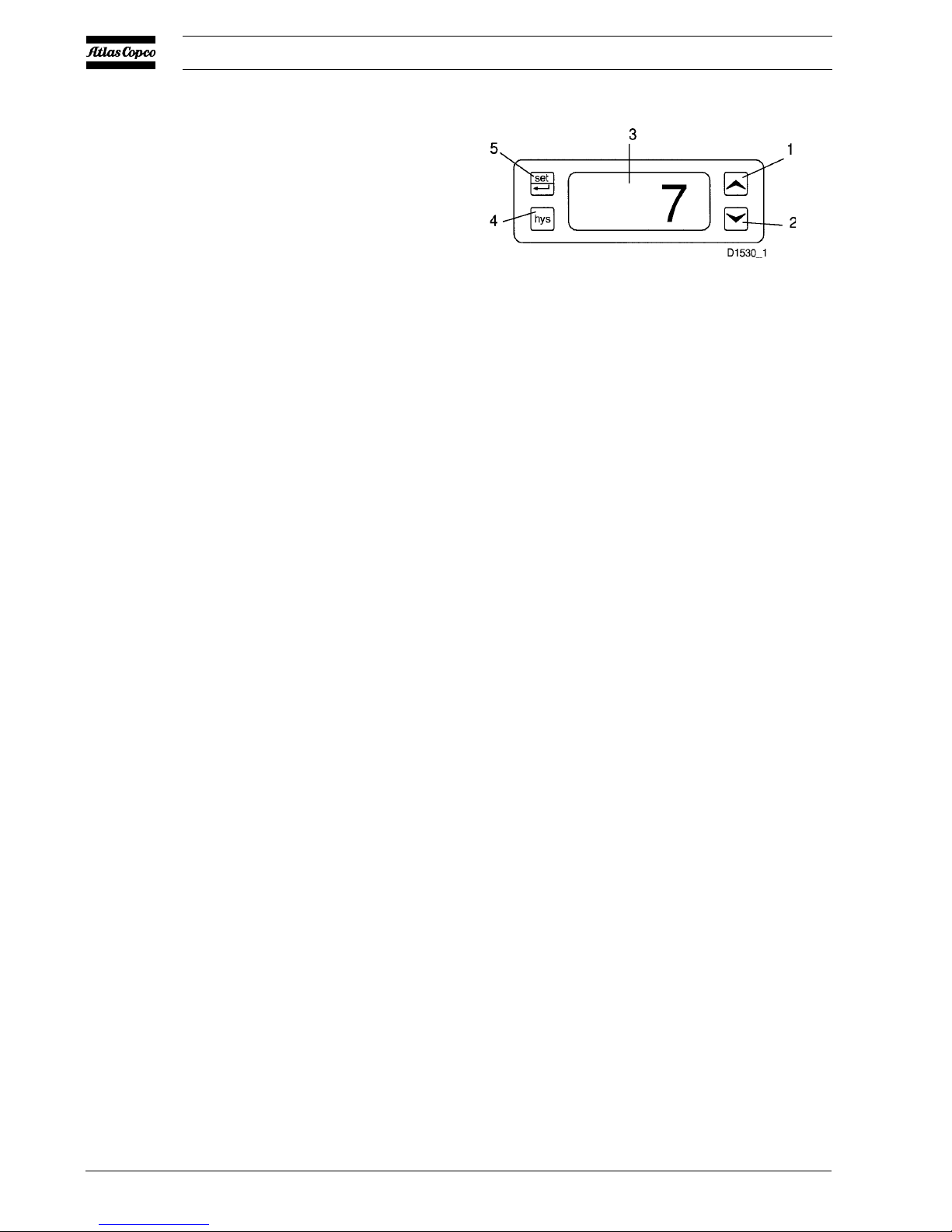
1.4 Automatic regulation system . . . . . . . . . . . . . . . . . 4
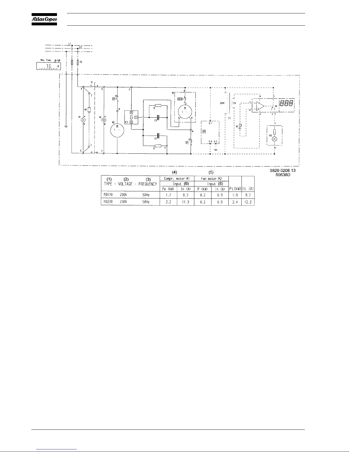
1.5 Electrical system . . . . . . . . . . . . . . . . . . . . . . . . . . . 4
2 Installation . . . . . . . . . . . . . . . . . . . . . . . . . . . . . . . . . . . 9
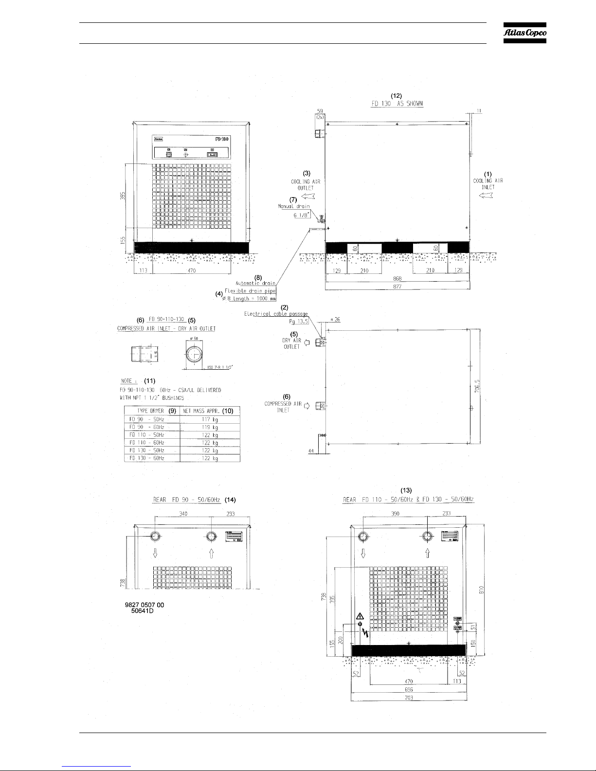
2.1 Dimension drawings . . . . . . . . . . . . . . . . . . . . . . . . 9
2.2 Installation proposal . . . . . . . . . . . . . . . . . . . . . . . 11
2.3 Installation instructions . . . . . . . . . . . . . . . . . . . . 12
2.4 Pictograp s . . . . . . . . . . . . . . . . . . . . . . . . . . . . . . 13
3 Operating instructions . . . . . . . . . . . . . . . . . . . . . . . . 13
3.1 Initial start . . . . . . . . . . . . . . . . . . . . . . . . . . . . . . . 13

2920 1390 02 3
Instruction book
1 LEADING PARTICULARS
1.1 General description
T e FD air dryers remove moisture from compressed air by
cooling t e air to near freezing point. T is causes water to
condense. T e condensate is automatically drained. T e air is
warmed up before leaving t e dryer.
1.2 Air circuit (Fig. 1.2)
Compressed air enters eat exc anger (13) and is cooled by
t e outgoing, cold, dried air. Water in t e incoming air starts to
condense. T e air t en flows t roug eat exc anger/
evaporator (11) w ere t e refrigerant evaporates causing t e
air to be furt er cooled to close to t e evaporating temperature
of t e refrigerant. More water in t e air condenses. T e cold
air t en flows t roug separator (3) w ere all t e condensate
is separated from t e air. T e condensate collects in condensate
trap (4) and is automatically drained. T e cold, dried air flows
t roug eat exc anger (13), w ere it is warmed up by t e
incoming air to approx. 10 degrees Celsius below t e incoming
air temperature. Condensation in t e air net cannot occur unless
t e air is cooled to below t e pressure dewpoint indicated by
gauge (1).
1.3 Refrigeration circuit (Fig. 1.2)
Compressor (M1) delivers ot, ig -pressure refrigerant gas
w ic flows t roug condenser (9) w ere most of t e refrigerant
condenses.
T e liquid flows t roug liquid refrigerant dryer/filter (12) to
capillary tube (7). T e refrigerant leaves t e capillary tube at
evaporating pressure.
T e refrigerant enters evaporator (11) w ere it wit draws eat
from t e compressed air by furt er evaporation at constant
pressure. T e eated refrigerant leaves t e evaporator and is
sucked in by t e compressor via accumulator (14).
M1. Refrigerant compressor
S3. Fan control switc
S7. Hig pressure s ut down switc
1. Control panel
2. Condenser
3. Hot gas by-pass valve
4. Liquid refrigerant dryer/filter
Fig. 1.1 General view of FD90
24S7 S3
1
3
M1
50643F

2920 1390 02
4
Instruction book
AI. Wet air inlet
AO. Dry air outlet
M1. Refrigerant compressor
M2. Condenser fan motor
S3. Fan control switc
S7. Hig pressure s ut down switc
1. Pressure dewpoint gauge
2. Insulating block
3. Condensate separator
4. Condensate trap
5. Automatic condensate drain ose
6. Manual condensate drain valve
7. Capillary tube
8. Condenser cooling fan
9. Refrigerant condenser
10. Hot gas by-pass valve
11. Air/refrigerant eat exc anger/
evaporator
12. Liquid refrigerant dryer/filter
13. Air/air eat exc anger
14. Accumulator
Fig. 1.2 Air and refrigerant flow diagram
1.4 Automatic regulation system (Fig. 1.2)
T e condenser pressure must be kept as constant as possible
to obtain stable operation, t erefore, fan control switc (S3)
stops and starts t e cooling fan.
W en, at partial or no load, t e evaporator pressure drops to
2.25 bar(e), t e by-pass regulator opens and ot, ig pressure
gas is fed to t e evaporator circuit to prevent t e evaporator
pressure from dropping any furt er.
1.5 lectrical system (Figs. 1.3 up to 1.6)
FD170 60Hz and FD230 60Hz dryers are 3-p ase units, all ot er
FD dryers are single-p ase units.
T e refrigerant compressors (M1) of FD170 and FD230 dryers
are equipped wit a crankcase eater (Rs). W en voltage is
supplied, t e eater is energized. It keeps t e oil in t e crankcase
warm to prevent condensing of refrigerant in t e compressor
ousing, w ic could result in serious damage of t e compressor
at start (liquid knock).

2920 1390 02 5
Instruction book
Fan control switc (S3) starts fan motor (M2) as soon as t e
condenser pressure reac es t e upper set point of t e switc
and will stop t e fan motor w en t e condenser pressure
decreases to its lower set point.
Hig pressure s ut-down switc (S7-Fig. 1.1) stops t e
compressor motor w en t e pressure in t e refrigerant circuit
reac es t e upper set point of t e switc . After tripping, it
must be reset manually by pressing its reset knob.
T e compressor motor as a built-in t ermic protection. If t e
compressor motor stops wit out apparent reason, it will
probably be t e t ermic protection w ic as tripped. In suc
case, t e compressor will restart w en t e motor windings ave
cooled down, w ic may take up to 2 ours.
C1. Start capacitor
C3. Run capacitor
F0. Main fuses, local installation
(customer's installation)
H1. Indicator lamp, VOLTAGE ON
H2. Indicator lamp, DEWPOINT
ALARM (optional)
K1. Timer (optional)
M1. Compressor motor
M2. Condenser fan motor
R. Resistor
R1. Temperature sensor, dewpoint
(optional)
S0. Main switc (customer's
installation)
S1. Button, ON-OFF
S3. Fan control switc
S4. Electronic t ermostat wit
display (optional)
S7. Hig pressure s ut down switc
T1. Transformer (optional)
Y1. Solenoid valve, interval drain
(optional)
Fig. 1.3 Electrical diagram of FD90 up to FD130

2920 1390 02
6
Instruction book
B1. Electronic condensate drain
(optional)
C1. Run capacitor
C3. Start capacitor
F0. Main fuses, local installation
(customer's installation)
H1. Indicator lamp, VOLTAGE ON
H2. Indicator lamp, DRYER RUN
H3. Indicator lamp, DEWPOINT
ALARM (optional)
K1. Start relay
M1. Compressor motor
M2. Condenser fan motor
R1. Temperature sensor, dewpoint
(optional)
RS. Crankcase eater
S1. Button, ON-OFF
S3. Fan control switc
S4. Electronic t ermostat wit
display (optional)
S7. Hig pressure s ut down switc
T1. Transformer (optional)
Fig. 1.4 Electrical diagram of FD170 50Hz and FD230 50Hz
F0. Main fuses, local installation
(customer's installation)
F3/4. Fuses
F8. T ermal overload, fan motor
H1. Indicator lamp, VOLTAGE ON
H2. Indicator lamp, DRYER RUN
H3. Indicator lamp, DEWPOINT
ALARM (optional)
K1. Contactor, compressor motor
K2. Contactor, fan motor
M1. Compressor motor
M2. Condenser fan motor
Q1. Circuit breaker
Q2. Circuit breaker
R1. Temperature sensor, dewpoint
(optional)
RS. Crankcase eater
S0. Main switc (customer's
installation)
S1. Button, ON-OFF
S2. Hig pressure s ut down switc
S3. Fan control switc
S4. Electronic t ermostat wit
display (optional)
T1. Transformer (optional)
1x1. Terminal strip
1x2. Terminal strip
Figs. 1.5 and 1.6

2920 1390 02 7
Instruction book
Fig. 1.5 Electrical diagram of FD170 220/440V/60Hz and FD230 220/440V/60Hz
Fig. 1.6 Electrical diagram of FD170 575V/60Hz and FD 230 575V/60Hz

2920 1390 02
8
Instruction book
An electronic t ermostat (Fig. 1.7) wit display and alarm
functions is available as an option. Display (3) s ows t e
pressure dewpoint. T e set point value, i.e. t e pressure
dewpoint at w ic t e alarm indicator lamp lig ts up, can be
c ecked by pressing key (5); t e value will blink for approx. 5
seconds on t e display. T e differential value, i.e. t e
temperature difference between alarm on and alarm off, can be
c ecked by pressing key (4); t e value will blink on t e display
for approx. 5 seconds.
Altering t e set point value (indicated "L1")
- Press key (5); t e current value blinks on t e display.
- Press t e up (1) or down (2) key until t e desired value is
reac ed.
- To store t e new value, press key (5) or wait a few seconds.
Altering t e differential value (indicated "HY1")
- Press key (4); t e current value blinks on t e display.
- Press t e up (1) or down (2) key until t e desired value is
reac ed.
- Press key (5) or wait a few seconds to store t e new value.
If t e temperature increases above t e preset value, t e alarm
indicator lamp will lig t up.
1. Key, value up
2. Key, value down
3. Display
4. Key, differential value
5. Key, set point of maximum pressure dewpoint
Fig. 1.7 Detail of electronic dewpoint indicator (optional)

2920 1390 02 9
Instruction book
2 INSTALLATION
2.1 Dimension drawings (Figs. 2.1 and 2.2)
Fig. 2.1 Dimension drawing of FD90 up to FD130

2920 1390 02
10
Instruction book
Fig. 2.2 Dimension drawing of FD170 up to FD230

2920 1390 02 11
Instruction book
2.2 Installation proposal (Fig. 2.3)
1. FD dryer
2a. DD-type general-purpose prefilter
2c. PD-type afterfilter
3. Air receiver wit condensate drain
4. Pressure gauge
5. Drain pipe
6. Dryer outlet valve
7. By-pass system
8. By-pass valve
9. Dryer inlet valve
Fig. 2.3 Installation proposal
1. Insulating block wit eat exc angers
2. Condenser
3. Condensate separator
4. Condenser cooling fan
5. Accumulator
Fig. 2.4 Side view
1
3
2
4
5
51533F

2920 1390 02
12
Instruction book
2.3 Installation instructions
1. Install t e dryer w ere t e ambient air is as clean as possible
and w ere t e temperature of t e air will never exceed t e
limits (see section 7). Keep t e ventilation gratings of t e
dryer free.
If necessary, take action to avoid external influences (wind,
draug ts, etc.) t roug t e ventilation gratings of t e dryer,
as t ey may disturb t e cooling air flow.
2. Connect t e compressed air lines to t e marked inlet and
outlet pipes of t e dryer (Figs. 2.1 and 2.2). Provide an air
inlet valve and outlet valve. If a by-pass pipe and valve are
installed, t e dryer can be serviced w ile by-passing t e
dryer.
3. Fit manual condensate drain valve (2-Fig. 2.5).
Lay out t e condensate drain oses via a funnel towards a
drain collector to allow visual inspection. T e oses must
slope downwards. For draining of pure condensate, install
an oil/water separator; consult Atlas Copco.
If t e condensate drain as been led down outside t e
compressor room w ere it may be exposed to freezing
temperatures, it must be insulated.
4. A sticker dealing in s ort wit t e operating instructions
and explaining t e pictograp s is delivered wit t e
literature set. Affix t e sticker next to t e control panel.
Make yourself familiar wit t e instructions and pictograp s
explained.
5. On single-phase dryers: Fit t e electric plug to t e voltage
supply cable. Plug in t e dryer.
On 3-phase dryers: C eck t at t e primary side
connections of transformer (T1-Figs. 1.5 and 1.6)
correspond wit t e supply voltage.
C eck t at t e electrical installation corresponds to t e local
codes. T e dryer must be eart ed and protected against
s ort circuits by fuses of t e inert type in all p ases. An
isolating switc must be installed near t e dryer.
1. Pictograp , manual condensate drain
2. Manual condensate drain valve
3. Pictograp , automatic condensate drain
4. Automatic condensate drain
Fig. 2.5 Rear view
C3. Run capacitor
M1. Refrigerant compressor
M2. Condenser fan motor
S3. Fan control switc
S7. Hig pressure s ut down switc
1. Hot gas by-pass valve
2. Condenser
3. Condensate trap
4. Insulating block wit eat exc angers
5. Liquid refrigerant dryer/filter
6. Cubicle
Fig. 2.6 Side view
1
2
3
4
51534F
431
M1
C3
6S3S7M2
5
2
51541F

2920 1390 02 13
Instruction book
1. Switc off and depressurize t e dryer before starting
maintenance or repairs
2. Manual condensate drain
3. Automatic condensate drain
4. Pressure dewpoint
5. Dryer on-off
6. Voltage on
7. Dewpoint alarm
Fig. 2.7 Pictograp s
3 OPERATING INSTRUCTIONS
Safety precautions
T e operator must apply all relevant safety precautions,
including t ose mentioned in t is book.
Altitude operation
Consult Atlas Copco if operating above 3000 m.
3.1 Initial start
1. At least 4 ours before starting, t e mains supply to t e
dryer must be switc ed on to energize t e crankcase eater
of t e refrigerant compressor.
2. On 3-phase dryers (see section 1.5), press on-off button
(S1-Fig. 3.2). C eck t at t e sense of rotation of fan motor
(M2-Fig. 2.6) is correct. Cooling air must be drawn in
t roug t e condenser and blown over t e refrigerant
compressor to outside t e dryer. If wrong, switc off t e
voltage and reverse two of t e t ree p ase connections at
t e mains terminals.
3.2 Starting (Figs. 3.1 and 3.2)
1. On FD170 and FD230, switc on t e voltage 4 ours before
starting to energize t e crankcase eater. Voltage on lamp
(H1) is alig t.
2. If installed, close t e dryer by-pass valve.
3. Press on-off button (S1).
4. Open t e dryer air inlet valve (customer's installation).
5. Approx. 5 minutes later, open t e dryer air outlet valve
(customer's installation).
6. Approx. 10 minutes later, t e nominal dewpoint will be
reac ed.
H1. Indicator lamp, VOLTAGE ON
H2. Indicator lamp, DRYER RUN
S1. Button, ON-OFF
1. Pressure dewpoint indicator
2. Pictograp , pressure dewpoint
3. Pictograp , dryer on-off
4. Pictograp , dewpoint alarm
5. Pictograp , voltage on
Figs. 3.1 and 3.2
Fig. 3.1 Control panel of FD90 up to FD130
(typical example)
Fig. 3.2 Control panel of FD170 and
FD230 (typical example)
2.4 Pictographs (Fig. 2.7)
50647F
2
14S1/H1
3
1
2
3
4
S1/H2 H1
5
50642F

2920 1390 02
14
Instruction book
3.3 During operation
Regularly c eck:
1. Pressure dewpoint indicator (1-Figs. 3.1 and 3.2). 1)
2. T at condensate is disc arged (4-Fig. 2.5). T e amount
depends on t e operating conditions.
3. Regularly open manual drain valve (2-Fig. 2.5) for approx.
10 seconds to disc arge condensate and possible impurities.
3.4 Stopping (Figs. 3.1 and 3.2)
1. Close t e dryer inlet and outlet valves (customer's
installation).
2. Press on-off button (S1). T e dryer stops. Voltage on lamp
(H1) remains alig t. On FD170 and FD230, t e crankcase
eater remains switc ed on. Leave t e voltage on if t e
dryer as to remain stand-by.
4 MAINTENANCE
Cooling dryers of FD type contain refrigerant HFC.
Safety precautions
W en andling refrigerant R404a, all applicable safety
precautions must be observed. T e following points are
stressed:
- Contact of refrigerant wit t e skin will cause freezing.
Special gloves must be worn and in case of contact, t e
skin s ould be rinsed wit water. On no account may
clot ing be removed.
- Fluid refrigerant will also cause freezing of t e eyes;
t erefore, safety glasses are a must.
- Refrigerant R404a is poisonous. Do not in ale refrigerant
vapours. C eck t at t e working area is adequately
ventilated.
Local legislation may impose that:
- work in t e refrigerant circuit of t e cooling dryer or on
any equipment w ic influences its function s ould
according to t e law be executed by an authorized control
body.
- t e installation s ould according to t e law be c ecked once
a year by an authorized control body.
General
- Keep t e dryer clean.
- Brus or blow off t e finned surface of condenser (2-Fig.
1.1) regularly.
- Once every six mont s inspect and clean t e inner
components of condensate trap (3-Fig. 2.6).
5 SETTINGS
T e regulating and safety devices are factory-adjusted to obtain
optimum performance of t e dryer. Do not alter t e setting of
any of t e devices.
6 PRO LEM SOLVING (Fig. 1.2)
1. Pressure de point too high
a. Air inlet temperature too ig
a. C eck and correct; if necessary, install a pre-cooler
b. Ambient temperature too ig
b. C eck and correct; if necessary, draw cooling air via a duct
from a cooler place or relocate dryer
c. Air inlet pressure too low
c. Increase inlet pressure
d. Dryer capacity exceeded
d. Reduce air flow
e. S ortage of refrigerant
e. Have circuit c ecked for leaks and rec arged
f. Refrigerant compressor (M1) does not run
f. See 3
g. Evaporator pressure too ig
g. See 6
. Condenser pressure too ig
. See 2
2. Condenser pressure too high or too lo
a. Fan control switc (S3) out of order
a. Replace
b. Fan or fan motor out of order
b. C eck fan/fan motor
c. Ambient temperature too ig
c. C eck and correct; if necessary, draw cooling air via a duct
from a cooler place or relocate dryer
d. Condenser externally clogged
d. Clean condenser
3. Compressor stops or does not start
a. Electric power supply to compressor is interrupted
a. C eck and correct as necessary
b. T ermic protection of refrigerant compressor motor (M1)
as tripped
b. Motor will restart w en motor windings ave cooled down
4. Condensate trap remains inoperative
a. Automatic drain system clogged
a. Flus t e assembly by opening manual drain valve. Have
system inspected
Footnote chapter 3
1) The pressure dewpoint will deviate from nominal if the air inlet conditions or volume flow differ from nominal.

2920 1390 02 15
Instruction book
5. Condensate trap continuously discharges air and ater
a. Automatic drain system out of order
a. Have system c ecked
6. Evaporator pressure is too high or too lo at unload
a. Hot gas by-pass valve incorrectly set or out of order
a. Have ot gas by-pass valve adjusted
b. Condenser pressure too ig or too low
b. See 2
c. S ortage of refrigerant
c. Have circuit c ecked for leaks and rec arged
7 PRINCIPAL DATA
7.1 Limitations/nominal conditions
50 Hz 60 Hz
Nominal conditions
Compressed air inlet pressure . . . . . . . . . . . . . . . . . . . . . . . . . bar(e) 7 7
Compressed air inlet temperature . . . . . . . . . . . . . . . . . . . . . . . Celsius 35 38
Ambient temperature . . . . . . . . . . . . . . . . . . . . . . . . . . . . . . . . Celsius 25 38
Inlet relative vapour pressure . . . . . . . . . . . . . . . . . . . . . . . . . . 1 1
Pressure dewpoint . . . . . . . . . . . . . . . . . . . . . . . . . . . . . . . . . . Celsius 3 4
Cooling air inlet temperature . . . . . . . . . . . . . . . . . . . . . . . . . . Celsius 25 38
Limitations
Maximum compressed air inlet pressure . . . . . . . . . . . . . . . . . bar(e) 13 13
Min.-max. ambient air temperature . . . . . . . . . . . . . . . . . . . . . Celsius 0-45 0-45
Min.-max. compressed air inlet temperature . . . . . . . . . . . . . . Celsius 0-55 0-55
7.2 Specific data of FD90, FD110 and FD130 1)
FD90 FD110 FD130
Volume flow at dryer inlet at nominal conditions . . . . . 50 Hz l/s 90 110 130
60 Hz l/s 92 113 135
Pressure drop t roug dryer at nominal conditions,
approx. . . . . . . . . . . . . . . . . . . . . . . . . . . . . . . . . . . . . . . . . . . . . . . . . . bar 0.16 0.15 0.21
Electric power input . . . . . . . . . . . . . . . . . . . . . . . . . . . . 50 Hz kW 1.30 1.40 1.90
60 Hz kW 1.80 2.30 2.30
Refrigerant
Tetrafluoroet ane CH2FCF3. . . . . . . . . . . . . . . . . . . . . . . . . . . . . . . . . R404a R404a R404a
Total c arge, approx. . . . . . . . . . . . . . . . . . . . . . . . . . . . 50 Hz kg 0.80 1.00 1.10
60 Hz kg 1.00 1.10 1.10

2920 1390 02
16
Instruction book
7.3 Specific data of FD170 and FD230 1)
FD170 FD230
Volume flow at dryer inlet at nominal conditions . . . . . . . . . . . . . . . . 50 Hz l/s 170 230
60 Hz l/s 175 235
Pressure drop t roug dryer at nominal conditions, approx. . . . . . . . . 50 Hz bar 0.22 0.22
60 Hz bar 0.25 0.22
Electric power input . . . . . . . . . . . . . . . . . . . . . . . . . . . . . . . . . . . . . . . 50 Hz kW 1.90 2.40
60 Hz kW 3.60 3.60
Refrigerant
Tetrafluoroet ane CH2FCF3. . . . . . . . . . . . . . . . . . . . . . . . . . . . . . . . . R404a R404a
Total c arge, approx. . . . . . . . . . . . . . . . . . . . . . . . . . . . . . . . . . . . . . . 50 Hz kg 1.80 1.80
60 Hz kg 1.60 1.70
Footnote chapter 7
1) At nominal conditions.
8 CONVERSION LIST OF SI UNITS INTO RITISH UNITS
1 bar = 14.504 psi
1 g = 0.035 oz
1 kg = 2.205 lb
1 km/ = 0.621 mile/
1 kW = 1.341 p (UK and US)
1 l = 0.264 US gal
1 l = 0.220 Imp gal (UK)
1 l = 0.035 cu.ft
1 m = 3.281 ft
1 mm = 0.039 in
1 m3/min = 35.315 cfm
1 mbar = 0.401 in wc
1 N = 0.225 lbf
1 Nm = 0.738 lbf.ft
x degrees Celsius = (32 + 1.8x) degrees
Fa ren eit 1)
Footnote chapter 8
1) A temperature difference of 1 degree Celsius = a temperature difference of 1.8 degrees Fahrenheit
This manual suits for next models
4
Table of contents
Other Atlas Copco Dryer manuals