9
PAGE
Repair Instructions Nr.183.09/00
PHE 50 S
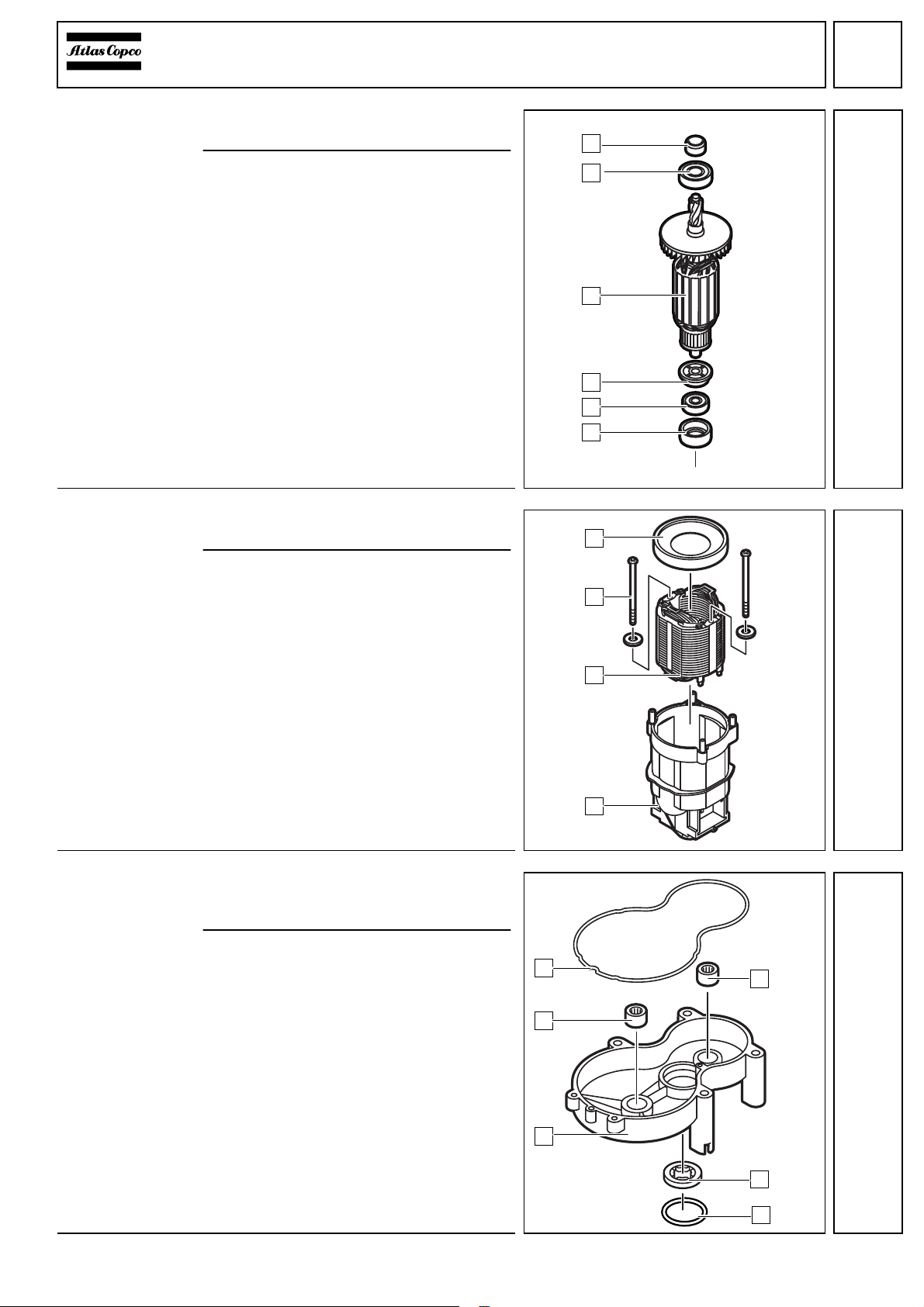
Assembly
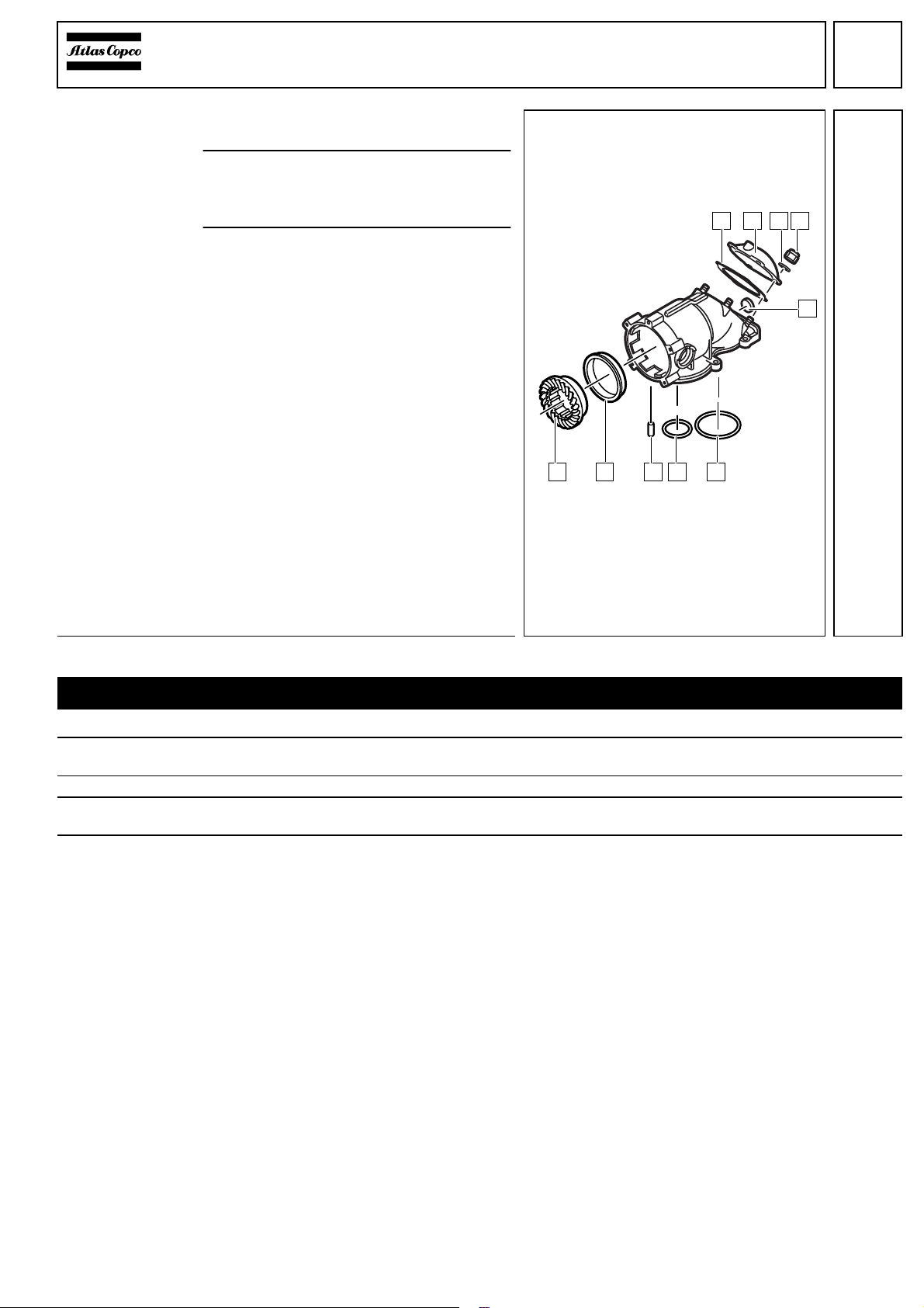
Mounting the
bevel wheel 1Press the bearing (2) flush into the gear
housing (6).
Press the bevel wheel (1) into the bear-
ing (2).
2Mount the O-rings (4) and (5) and press in
the two pins (3).
3Insert the O-ring (7) into the groove of the
gear housing.
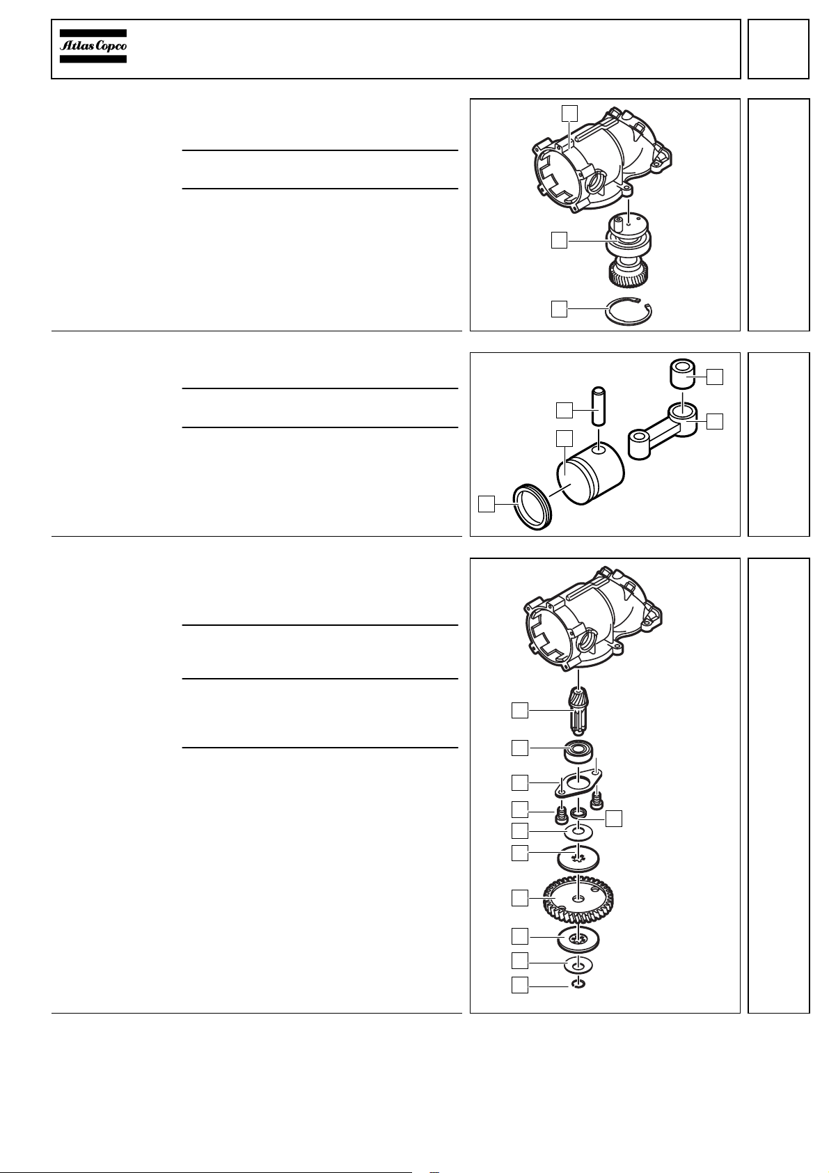
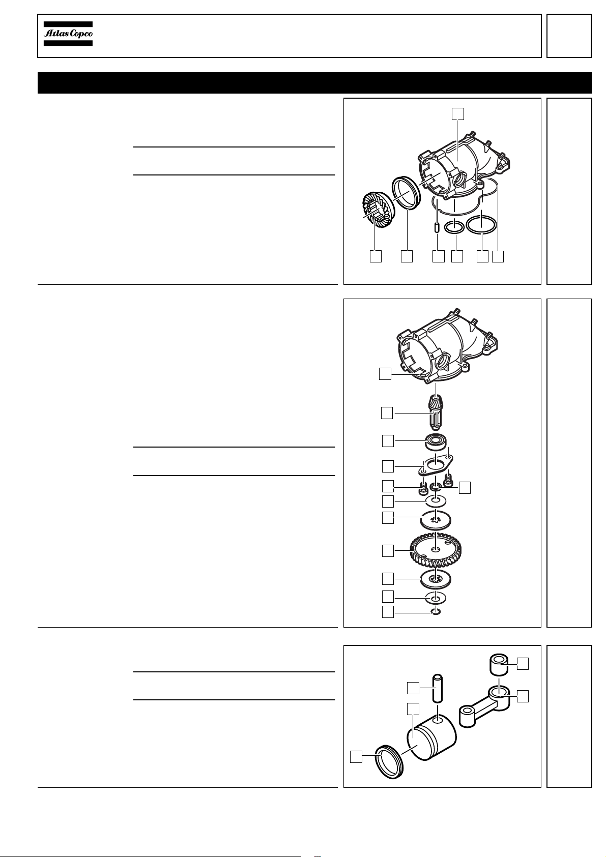
Assembling
the drive 1Press the ball bearing (9) onto the pin-
ion (A) and mount the following parts one
after the other on the pinion (A):
spacer (B),
plate (8)
spring plate (6),
friction disc (5),
drive wheel (4),
friction disc (3),
spring plate (2).
☞Lightly grease discs (3) and (5) with
blue grease, type Mobilith HP 222.
2Mount the spring ring (1), depressing the
spring plate (2) at the same time.
3Insert the assembled drive into the gear
housing (C) and fix it with screws (7)
through the aligned plate (8).
☞Cover the screws (7) with screw lock-
ing device and tighten with 2 Nm.
☞Thesafety clutch can't beadjusted:In
case the drill bit does not rotate at low
load, please check the spring plates
and the clutch discs for wear. If neces-
sary, replace them.
Mounting the
connecting rod 1Mount the four-lips-seal-ring (1) to the pis-
ton (2).
2Press the bearing (4) into the connecting
rod (5).
3Push the connecting rod (5) into the pis-
ton (2) and secure it with the bolt (3).
6
5431 2 7
3
4
1
5
6
2
7
8
9
B
A
C
3
4
1
25