Gendex Expert DC User manual

Intraoral X-ray System
Gendex Dental Systems
901 West Oakton Street
Des Plaines, IL 60018 U.S.A.
Tel 1-888-275-5286
Fax 1-847-550-1322
www.gendex.com
Authorized Representative:
KaVo Dental GmbH
Bismarckring 39
88400 Biberach, Germany
www.gendex-dental.com
www.kavo.com
Installation Manual
Installation Manual

Gendex Dental Systems
901 West Oakton Street
Des Plaines, IL 60018 U.S.A.
Tel 1-888-275-5286
Fax 1-847-550-1322
www.gendex.com
Authorized Representative:
KaVo Dental GmbH
Bismarckring 39
88400 Biberach, Germany
www.gendex-dental.com
www.kavo.com
Installation Manual

032-0204-EN Rev 4 -iii
Chapter 1 - Preinstallation
General Information ............................................................................................ 1-1
Certified Component ...................................................................................................1-1
Environmental Factors ................................................................................................1-1
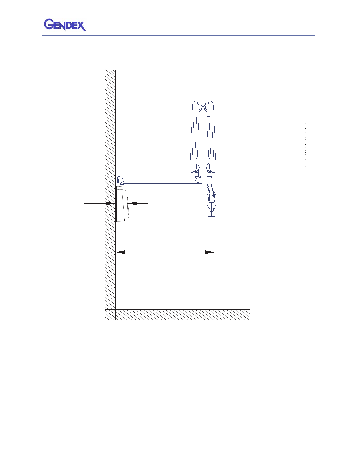
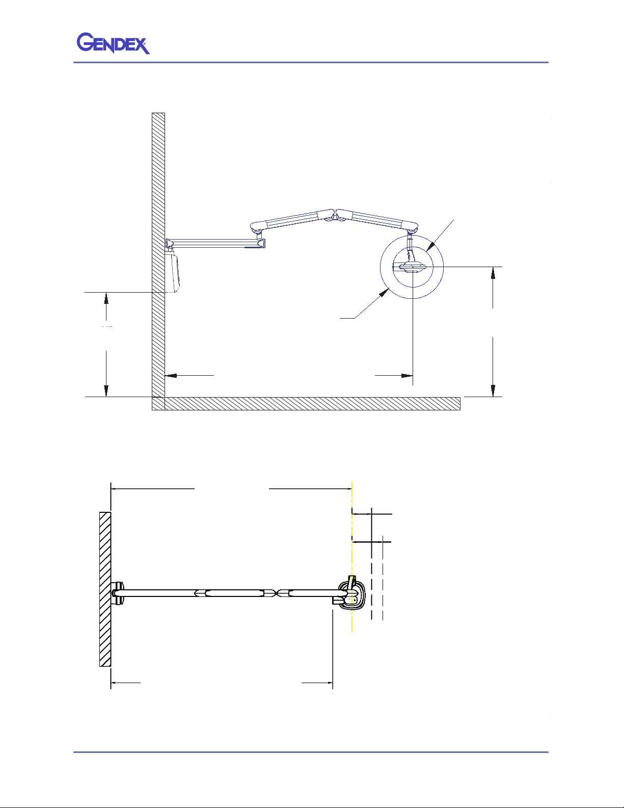
Reach and Coverage ...................................................................................................1-1
Electrical Power Requirements ....................................................................................1-6
Wall Support Considerations ......................................................................................1-7
Additional Kits Available .............................................................................................1-8
Chapter 2 - Installation
Install Master Control Touch Panel ...................................................................... 2-1
Install Master Control .......................................................................................... 2-4
Mount to Single Wood Wall Stud .................................................................................2-5
Mount to Wood Wall Studs (16-inch Center) ................................................................2-6
Mount to a Solid Wall ..................................................................................................2-8
Mount in a Pass-through Box or Cabinet System .........................................................2-9
Mount to Wall with Steel Studs .................................................................................2-10
Final Steps to Install Master Control .................................................................. 2-11
Install Horizontal Arm ....................................................................................... 2-12
Install Articulated Arm & Tubehead Assembly ................................................... 2-15
Connect Cabling and Wires ................................................................................ 2-18
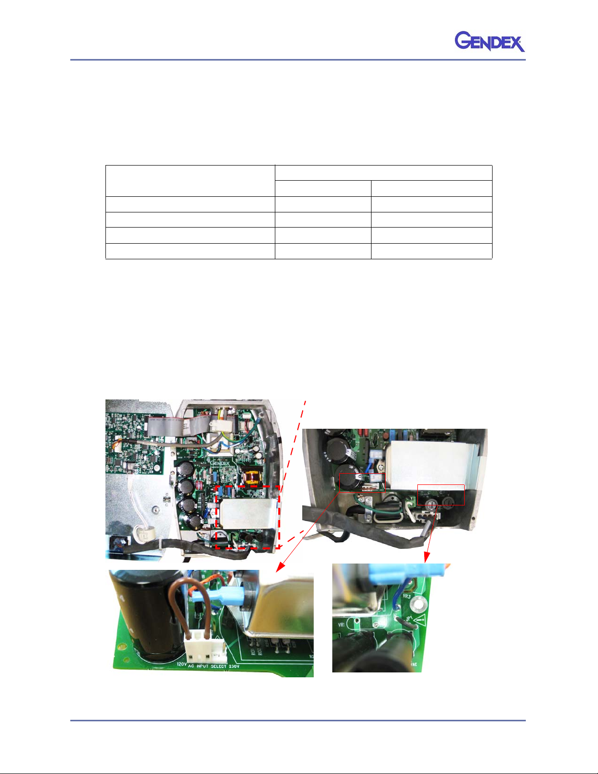
Electrical Power Connection .............................................................................. 2-23
Complete the Installation .................................................................................. 2-26
Local Touch Panel .....................................................................................................2-26
Remote Touch Panel .................................................................................................2-28
Articulated Arm Vertical Drift Adjustment .......................................................... 2-30
Chapter 3 - System Checks
Electrical Calibration Checks ............................................................................... 3-1
Configure Exposure Settings ............................................................................... 3-2
Final System Checks ........................................................................................... 3-3
Table of Contents

Table of Contents
032-0204-EN Rev 4
-iv

032-0204-EN Rev 4 1-1
Chapter
1Preinstallation
General Information
This section provides information on the product configuration, reach and coverage, support
requirements and electrical power requirements.
Certified Component
Environmental Factors
The equipment is intended for indoor use for normal dental applications within these
ranges:
Reach and Coverage
The reach of the system is measured from the tip of the cone with the arm fully
extended and the cone pointing back toward the pivot of the wall plate. This
measurement method accommodates the normal positioning of the Tubehead to the
patient. A patient can therefore be positioned without difficulty with the chair located
within a radius outward from the pivot point to the dimensions listed below.
The Gendex expert®DC is available with three different lengths of the horizontal arm.
This allows the system to have three different areas of reach. The lengths available
allow reaches of 59 inches (150 cm), 69 inches (175 cm), or 79 inches (200 cm).
Component Reference No. Label Location
Tubehead 110-00210G1 Underside of Yoke
Master Control 110-0205G1 Underside of Master Control
Collimator 112-0951G1 Inside of Cone
Temperature 10 to 40° C (50 to 104° F)
Air Pressure 700 hPa to 1060 hPa (0.7 bar to 1.060 bar)
Humidity 30 to 90 percent

Expert DC Installation Manual
032-0204-EN Rev 41-2
NOTE: The reaches listed are for the 79-inch (200 cm) arm supplied with the 8-inch (20 cm) cone.
Using the optional 12-inch (30 cm) cone will reduce the arm reach by 4 inches (10 cm).
Maximum and Minimum Reach Diagram
Gendex eXpert DC75 W/8" (20 cm) CONE
26" (66 cm) MIN REACH
79" (200 cm) MAX REACH
Gendex eXpert DC55 W/8" (20 cm) CONE
11” (28 cm) WHEN
TUBE IS ROTATED WITH
12” (31 cm) CONE
7” (18 cm) WHEN
TUBE IS ROTATED WITH
8” (20 cm) CONE
79” (200cm) Maximum Reach
with 8” (20cm) Cone
26” (66cm) Minimum Reach
with 8” (20cm) Cone
7” (18cm) When
Tube is Rotated with
8” (20cm) Cone
11” (28cm) When
Tube is Rotated with
12” (31cm) Cone

Preinstallation
032-0204-EN Rev 4 1-3
Side View
(105 cm)
41-1/4"
(12.5 cm)
4-7/8"
5-1/2”
(13.97cm)
Gendex eXpert DC 75 - D
Gendex eXpert DC 65 - S
d
Gendex eXpert DC 55 - S
d
A
5-1/2”
(13.97cm)
41-1/4” (105cm)
with 79” Arm
Subtract 10” (25cm)
with 69” Arm
Subtract 20” (51cm)
with 59” Arm

Expert DC Installation Manual
032-0204-EN Rev 41-4
Front View
(117.5cm)
46-1/4"
8"
(36.5cm)
14-1/2"
TYPICAL
39" (99cm)
(20.5cm)
15-0”
(38.1cm)
9”
(22.86cm)
Gendex eXpert DC 75 - Dimens
Gendex eXpert DC 65 - Subtrac
dimens
Gendex eXpert DC 55 - Subtrac
dimens
A
46-1/4” (117.5cm)
with 79” Arm
Subtract 10” (25cm)
with 69” Arm
Subtract 20” (51cm)
with 59” Arm
9”
(22.86cm)
15”
(38.1cm)
39”
(99 cm)
Typical

Preinstallation
032-0204-EN Rev 4 1-5
Side View (extended)
Top View
(119.5 cm)
47"
W/8" (20cm) CONE
14" (35.5cm) DIAMET
W/12" (30.5cm) CONE
22" (55.9 cm) DIAMETER
86-1/2" (220 cm)
(99 cm)
39"
Gendex eXpert DC 75 - Dimension A is as shown
Gendex eXpert DC 65 - Subtract 10” (25 cm) from
dimension A
Gendex eXpert DC 55 - Subtract 20” (51 cm) from
dimension A
A
39”
(99 cm)
22” (55.9 cm) Diameter
with 12” (30.5 cm) Cone
14” (35.5 cm) Diameter
with 8” (20 cm) Cone
47”
(119.5 cm)
86-1/2” (220cm) with 79” Arm
Subtract 10” (25cm) with 69” Arm
Subtract 20” (51cm) with 59” Arm
Gendex eXpert DC 75 - Dimension A is as show
Gendex eXpert DC 65 - Subtract 10” (25 cm) fro
dimension A
Gendex eXpert DC 55 - Subtract 20” (51 cm) fro
dimension A
A
79” (200cm) Maximum Reach
with 8” (20cm) Cone,
75” (190cm) with 12” (30.5cm) Cone
Subtract 10” (25cm) with 69” Arm
Subtract 20” (51cm) with 59” Arm
7” (17.8 cm)
When Tube is Rotated
with 8” (20cm) Cone
11” (27.9 cm)
When Tube is Rotated
with 12” (30.5cm) Cone
86-1/2” (220 cm)

Expert DC Installation Manual
032-0204-EN Rev 41-6
Electrical Power Requirements
The system requires a three-wire electrician-supplied power supply: A ground wire and
two power lines: (L) Line and (N) Neutral.
NOTE: The line cord option can be purchased with the system. This option is only
permitted for 120 V ac installations. It is not recommended for voltages other than
120 V ac. To prevent damage to the unit, before installing the line cord:
•set the AC Input Selector Jumper to the proper voltage range of the
supplied mains, and
•cut jumper JP1 on the Converter Board (4mm gap minimum) this
enables the Neutral line fuse. Refer to Electrical Power Connection
on page 2-23 to ensure proper wiring of the device.
Modifications for Line Cord Installation
Nominal Voltage
120 V ac ± 10% 230 V ac +10%, -14%
Line Current (Standby Mode) 0.5 Amp 0.3 Amp
Line Current (Exposure Mode) 8 Amp 4 Amp
Mains Current Fuse 10 Amp 250 V 10 Amp 250 V
Max Line Resistance 0.4 ohm 1.0 ohm

Preinstallation
032-0204-EN Rev 4 1-7
Wall Support Considerations
Verifying the wall support capability is the responsibility of the installer. Appropriate
fasteners are included for single-stud installation only.
WARNING
The installer must use the
supplied
3 1/2” lag bolts, flat washers, and split
lock rings, when installing an Expert DC system. Failure to comply may result
in the X-ray device falling off the wall and an injury may occur.
Substituting or replacing any mounting hardware that is provided with the equipment
may void the warranty. Any property damage or personal injury resulting from an
improper installation could become the responsibility of the installer(s).
The wall support and mounting hardware for the Gendex expert®DC unit must
withstand these maximum forces:
The Master Control unit of the Gendex expert®DC system is designed to be mounted
on a single wood 2"x 4" stud or equivalent wall support. The hole pattern on the back
plate of Master Control is configured to accommodate these types of installation:
•Mounted to two wooden wall studs spaced at 16" (41 cm) (using the optional Wall
Plate D800WPEXPERT)
•Mounted to a solid wall (concrete or similar construction)
•Mounted to a wall supported by steel studs (using the optional Wall Plate,
D800WPEXPERT and the optional Backing Plate, D800BPEXPERT)
•Mounted in a pass-through box or cabinet system
Use the template provided to position the Master Control properly. The template also
specifies the correct placement of the Master Control Touch Panel when mounted
remotely.
For all installations, the bottom of the Master Control unit, or the Wall Plate to which it
is mounted, should be located at approximately 39" (99cm) above the floor. (The large
range of travel of the suspension arm provides some flexibility in the vertical position.)
A summary for each type of mounting is given in the table that follows:
Shear load 60lbs (27 kg)
Withdrawal force at each mounting screw/bolt 400 lbs (182 kg)
Load moment capability of wall fabrication and
attachments to the building structure 850 ft. lbs (118 kg m)
Mounting support Install junction box If Operator Panel is installed remotely,
install junction box (1)
Single wooden wall
stud Left of the mounting stud at the
appropriate height Left of the mounting stud above the
power supply junction box

Expert DC Installation Manual
032-0204-EN Rev 41-8
Additional Kits Available
Read the installation instructions provided with the kits before starting to install
Gendex expert®DC. Some kits require that additional access holes be made before the
Master Control or the Mounting Plate for the Master Control is mounted.
NOTE: Unless additional kits are purchased, the exposure switch on the Master
Control Touch Panel and the attached Coil-Cord Exposure Switch are the only
switches available. In order to comply with regulations and proper x-ray
practices, the Master Control Touch Panel or additional exposure switches
must be located where the operator can view both the patient and the
technique factors prior to the exposure.
In the event you are not installing an application described in the manual, please contact your
Gendex Sales Representative, who can consult with Gendex Engineering Department, prior to
install.
Two wooden wall
studs spaced at 16"
(41 cm)
Right of the left mounting stud at
the appropriate height Right of the left mounting stud above
the power supply junction box
Solid wall Left of mounting bolts Left of the mounting stud above the
power supply junction box
Steel studs Right of the left mounting stud at
the appropriate height Right of the left mounting stud above
the power supply junction box
Wall Pass-Through
or Cabinet System Using the template as guide, refer
to the manufacturer
(1) 2x4 power supply junction box is only necessary where required by local codes.
Kit Kit Description
D800HK Pushbutton Wiring Kit Two possibilities:
- One or more remote exposure switches have been
previously installed. The exposure switch on the Master
Control Touch Panel is disabled.
- A remote exposure switch is already installed. This
switch and the switch on the Master Control Touch Panel
must be pressed simultaneously to make the exposure.
D0765LS Lighted Pushbutton A remote exposure switch is installed. A light on the switch
indicates when x-rays are being emitted. The exposure
switch on the Master Control Touch Panel is disabled.
Remote Cable Adapter Kit - Part
No. - 110-0160G1 This kit provides for connecting the Operator Control
remote cable to the Control Box by means of a terminal
strip instead of the modular connector. This may be
required if the control cable is run in conduit.
Mounting support Install junction box If Operator Panel is installed remotely,
install junction box (1)

032-0204-EN Rev 4 2-1
Chapter
2Installation
Ensure that all preinstallation requirements are completed prior to beginning installation.
1. Are all the wall support requirements adequate for mounting the unit?
2. Have all the electrical power requirements been met?
3. Do all wires have proper routing locations?
Tools required for installation:
•Metric Allen hex wrench set
•Screwdrivers (slot/Phillips)
•Drill and drill bits for wall mounting
•Sockets and ratchet driver for wall mounting
•Fluke model 73 DVM equivalent or better
•Level
Install Master Control Touch Panel
The recommended configuration is to mount the Gendex expert®DC with the Master
Control inside the X-ray room and the Master Control Touch Panel outside of that room.
(When located apart from the Master Control, the Master Control Touch Panel is referred
to as the “Remote Touch Panel.”)
The Master Control Touch Panel can be mounted directly on the Master Control. This is
not recommended as it is important to be able to view the technique factors prior to the
exposure. (When attached directly to the Master Control, the Master Control Touch
Panel is referred to as the “Local Touch Panel.”)
Both the Remote and Local mounting location of the Touch Panel are described in the
section Complete the Installation, page 2-26.
For Local Touch Panel procedures, skip to Install Master Control, page 2-4.
Remote Touch Panel procedures are as followed.
1. Open the shipping carton and locate the Master Control Touch Panel, the
Mounting Plate, and the 50-foot (15-meter) Control Cable in the top
portion of the shipping carton.

Master Control Touch
Panel Mounting Plate and
Control Cable
Mounting Studs
AA
AB
B
B
Expert DC Installation Manual
032-0204-EN Rev 42-2
2. Set the Master Control Touch Panel aside to be installed later.
NOTE: Before attaching the Mounting Plate, to ensure you orient the plate correctly,
take note of the two mounting studs at the top of the plate.
3. Refer to the supplied Mounting Template to select the mounting location.
Attach the Mounting Plate in the desired location with the three supplied
Phillips head screws and wall anchors at positions A. Or, the three wood
screws provided with the plate may be used to mount the plate over a
wood 2x4 stud at positions B.

Installation
032-0204-EN Rev 4 2-3
NOTE: In the following step, route the Control Cable in compliance with local codes.
The cable can also be run to an electrical box. If installing the Master Control
on the optional Wall Plate, refer to step 3 on page 2-6 for routing instructions
for the control cable at the Wall Plate.
4. Fish the Control Cable from the Master Control Touch Panel to where the
Master Control will be located. Extend the cable out through the wall to a
length that will extend past the bottom front of the Master Control (once
mounted).

Master Control
Remove Screws
Expert DC Installation Manual
032-0204-EN Rev 42-4
Install Master Control
1. Locate the Master Control in the top portion of the carton.
2. Remove the two Phillips head screws from the Hinged Cover and carefully
open the cover. Place the two screws in a safe location for future
reassembly.
Several possibilities exist for installing the Master Control:
•Single wood wall stud (Mount to Single Wood Wall Stud, page 2-5)
•16 inch center studs (Mount to Wood Wall Studs (16-inch Center),
page 2-6)
•Solid wall (Mount to a Solid Wall, page 2-8)
•Pass-through (Mount in a Pass-through Box or Cabinet System, page
2-9)
•Wall with steel studs (Mount to Wall with Steel Studs, page 2-10)

Installation
032-0204-EN Rev 4 2-5
Mount to Single Wood Wall Stud
1. Determine the proper location for mounting the unit. Referring to the
Mounting Template, verify that each electrical box is positioned correctly
in relation to location of the mounting stud.
2. Position the template or the Master Control itself at the appropriate
height. Mark the wall for the mounting holes.
NOTE: If using the Master Control for marking, lay the unit aside before continuing.
3. Drill pilot holes for the mounting bolts. Remove the Mounting Template (if
used).
4. Route the power supply wires and, if used, the Control Cable from the
Master Control Touch Panel, into the Master Control.
5. Place the Master Control into position, and start the upper mounting bolt.
Do not tighten.
6. To complete installation for the Master Control, go to Final Steps to Install
Master Control, page 2-11.

NOTE 2
NOTE 3
NOTE 1
NOTE 1 NOTE 1
NOTE 1
NOTE 5
NOTE 2
NOTE 4
NOTE 4
NOTE 3
MOUNTING WITH D800WP
SPECIAL 16" CENTER WALL PLATE
NOTE 1:
HOLE LOCATIONTO MOUNT THE WALLPLATE VIA LAG BOLTS(SUPPLIED) TO WOODEN WALLSTUDS SPACED AT16" (40.6cm). MAXIMUM BOLT DIAMETER IS 10mm OR 3/8". BEFORE MOUNTING, VERIFY THATWALLSUPPORT AND HARDWARE
MEET THE SUPPORTREQUIREMENTS LISTED ON THE OTHER SIDE.
NOTE 2:
THREADED HOLES TO MOUNTMASTER CONTROL BOX TO WALL PLATEWITH BOLTS SUPPLIED WITH WALLPLATE.
NOTE 3:
ELECTRICAL POWER ENTRYPOINT. UNIT MUST BE CONNECTED TO ELECTRICIAN SUPPLIED POWER PER THE REQUIREMENTS LISTED ONTHE OTHER SI DE. JUNCTION BOX POSITION SHOWN.
NOTE 4:
ENTRYPOINT FOR THE INTERCONNECTING CABLE USED WHEN REMOTELY MOUNTINGTHE OPERATOR CONTROL PANEL. JUNCTION BOX POSITION SHOWN.
NOTE 5:
ALTERNATIVE ENTRY POINT FORTHE INTERCONNECTING CABLE USED WHEN REMOTELY MOUNTING THE OPERATORCONTROL PANEL.
Route Power Supply Wires Through Lower Opening
Route Control Cable
Through Top Opening
Route Power Supply Wires
Through Lower Opening
Expert DC Installation Manual
032-0204-EN Rev 42-6
Mount to Wood Wall Studs (16-inch Center)
NOTE: Parts not provided in the shipping carton: Optional Wall Plate
(D800WPEXPERT)
1. Determine proper location for mounting the unit. Referring to the
Mounting Template, verify that each electrical box is positioned correctly
in relation to location of the mounting studs.
2. Position the template or the Wall Plate itself at the appropriate height.
Mark the wall for the four mounting holes.
NOTE: If using the Wall Plate for marking, lay the plate aside before continuing. Drill
pilot holes appropriate for the mounting bolts that will be used. Remove the
Mounting Template (if used).
3. Place the Wall Plate back into position while routing the power supply
wires into the bottom opening. If the Touch Panel is mounted remotely,
route the long Control Cable into the top opening.

NOTE 2
NOTE 3
NOTE 1
NOTE 1 NOTE 1
NOTE 1
NOTE 5
NOTE 2
NOTE 4
NOTE 4
NOTE 3
MOUNTINGWITH D800WP
SPECIAL16" CENTER WALL PLATE
NOTE1:
HOLELOCATIONTO MOUNT THE WALL PLATEVIA LAG BOLTS(SUPPLIED) TO WOODEN WALL STUDS SPACEDAT16" (40.6cm). MAXIMUMBOLTDIAMETER IS 10mm OR 3/8". BEFORE MOUNTING, VERIFY THATWALL SUPPORTAND HARDWARE
MEETTHE SUPPORTREQUIREMENTS LISTED ON THE OTHER SIDE.
NOTE2:
THREADEDHOLES TO MOUNT MASTER CONTROL BOXTO WALL PLATEWITH BOLTS SUPPLIED WITH WALLPLATE.
NOTE3:
ELECTRICALPOWER ENTRYPOINT. UNIT MUST BE CONNECTED TO ELECTRICIAN SUPPLIED POWER PER THE REQUIREMENTS LISTED ON THE OTHER SIDE. JUNCTION BOX POSITION SHOWN.
NOTE4:
ENTRYPOINT FORTHE INTERCONNECTING CABLE USED WHEN REMOTELY MOUNTING THE OPERATORCONTROL PANEL. JUNCTION BOX POSITION SHOWN.
NOTE5:
ALTERNATIVEENTRYPOINT FOR THE INTERCONNECTING CABLE USED WHEN REMOTELYMOUNTING THE OPERATORCONTROL PANEL.
Installation
032-0204-EN Rev 4 2-7
4. Using the mounting bolts supplied with the Wall Plate option, start the
top two mounting bolts. Do not tighten.
5. Verify the level of the Wall Plate and start the lower two mounting bolts.
Once the level of the Wall Plate is set correctly, tighten all mounting bolts.
6. Route the power supply wires and, if used, the Control Cable from the
Master Control Touch Panel, into the Master Control.
7. Place the Master Control into position and start the upper mounting bolt.
Do not tighten.
8. To complete installation for the Master Control, go to Final Steps to Install
Master Control, page 2-11.

Expert DC Installation Manual
032-0204-EN Rev 42-8
Mount to a Solid Wall
NOTE: Parts not provided in the shipping carton: Mounting bolts appropriate for
mounting to a solid wall.
1. Determine the proper location for mounting the unit. Referring to the
Mounting Template, verify that each electrical box is positioned correctly
in relation to location of the mounting studs.
NOTE: For the following step, the two main holes and/or the two alternate mounting
holes can be used.
2. Position the template or the Master Control itself at the appropriate
height. Mark the wall for the mounting holes.
NOTE: If using the Master Control for marking, lay the unit aside before continuing.
3. Drill pilot holes appropriate for the wall anchors that will be used.
Remove the Mounting Template (if used).
4. Route the power supply wires and, if used, the Control Cable from the
Master Control Touch Panel, into the Master Control.
5. Place the Master Control into position and start the upper mounting bolt.
Do not tighten.
6. To complete installation for the Master Control, go to Final Steps to Install
Master Control, page 2-11.
Other manuals for Expert DC
2
Table of contents
Other Gendex Medical Equipment manuals
Popular Medical Equipment manuals by other brands

GNATUS
GNATUS Optilight Series owner's manual

DentalEZ
DentalEZ Simplicity Installation, operation & care manual

Seers Medical
Seers Medical 6100 user manual

Covidien
Covidien Kangaroo 924 Directions for use

Galvin Engineering
Galvin Engineering ClevaCare CLEVA010 Installation guidelines

Welcare
Welcare WSP050 manual

Lady Technologies
Lady Technologies Kegg manual

GF Health Products
GF Health Products Basic American Liberty Series Instructions for use

Johnson & Johnson
Johnson & Johnson DePuy Synthes VIPER System Instructions for use

FujiFilm
FujiFilm SonoSite S Series user guide

U-Line
U-Line Pure Flow 1000 H-1297 installation manual

SAIC
SAIC RTR-4 Operator's manual