TekTone Tek-CARE160 User manual

Tek-CARE160 Wireless Nurse Call Installation Manual
Copyright©2001-2024 TekTone®Sound & Signal Mfg., Inc., All rights reserved.
No part of this publication may be copied without the express written permission of TekTone®Sound &
Signal Mfg., Inc. The content of this manual is furnished for informational use only, is subject to change
without notice, and should not be construed as a commitment by TekTone. TekTone Sound & Signal
Mfg., Inc. assumes no responsibility or liability for any errors or inaccuracies that may appear in this
documentation.
TekTone, the TekTone logo, Tek-ALERT, Tek-BRIDGE, Tek-CALL, Tek-CARE, Tek-CHECK-IN,
Tek-COM, Tek-ENTRY, Tek-GUARD, Tek-MICRO, Tek-MMARS, Tek-PAGING, and Tek-SAFE are
either registered trademarks or trademarks of TekTone®Sound & Signal Mfg., Inc. in the United States
and/or other countries. All other trademarks are the property of their respective owners.
TekTone®Sound and Signal Mfg., Inc., 324 Industrial Park Road, Franklin, North Carolina 28734,
USA.

Table of Contents
Introduction and Overview 4
Product Overview 5
Installation 8
Types of Installation 8
The NC160 Central Equipment Module 11
Wiring Installation 16
Connect Stations 19
LI122UN LED Color Configuration 21
Connect NC415G3/NC404TS Master Stations 26
Connect Data Bus Wiring 28
Connect Audio Bus Wiring 28
Connect Master Bus Wiring 28
Networking Multiple NC160 CE Modules 28
Configuration Setup 30
Connect the LS450 ConfigTool Programming Software 30
Configure an Autodetect Configuration 31
Configure a Custom System 37
Audio Adjustments 41
Using the Tek-CARE160 System 43
Placing and Resetting Calls 43

Introduction and Overview
Introduction
Welcome to the installation manual for the Tek-CARE160 Nurse Call System. This system
is designed to be low cost, easy to install, and extremely reliable. This manual will walk you
through the installation and configuration process, and will cover system operation as well as
common troubleshooting steps.
If you have questions at any point during the installation process, contact our Technical Sup-
828.524.9967. Choose Option 3 for Technical Support.
Overview
The Tek-CARE160 system is a versatile system that can satisfy the needs of a wide range of
facilities. At its core, the Tek-CARE160 system is a four-wire nurse call system designed for
easy installation and years of trouble-free operation. The system is available with a variety of
call stations such as two-button pull-cord stations, 1/4" jack call cord stations, duty stations,
dome lights, and more.
In addition to these items, the Tek-CARE160 system can be easily integrated with existing
TekTone nurse call systems, nurse call systems manufactured by other companies, as well as
a wide variety of building systems such as fire alarm systems, security and access control
systems, and much more.
The Tek-CARE160 system may be used as either a standalone nurse call system using
NC415G3/NC404TS Master Stations, or it may be connected to other TekTone nurse call
systems, such as the Tek-CARE400 family, Tek-CARE570, or Tek-CARE750 over the Tek-
CARE Network. With the addition of the LS601 Tek-ALERT Integration Manager, the Tek-
CARE160 system is capable of communicating with many other types of building systems,
such as fire alarm and security systems. The LS601 Tek-ALERT Integration Manager also
allows the system to display and log various events from older analog TekTone nurse call
systems such as the Tek-CARE NC110, NC150, NC200, and 300/III systems.
4|IL1024 Tek-CARE160 Installation Manual Copyright ©TekTone Sound and Signal Mfg., Inc. All Rights Reserved

Product Overview
NC160 Central Equipment Module: The Tek-CARE160 system's main
component is the NC160 Central Equipment (CE) Module. The CE module
is designed to be stackable or rack mountable. The NC160 CE Module can
operate as a standalone system, or as a module on a larger, integrated Tek-
CARE nurse call system. The NC160 CE Module provides connections for
64 room controllers, and six NC415G3 or ten NC404TS Master Stations.
Multiple CE modules may be networked together to create a larger system.
NC415G3 Master Station: The NC415G3 Master Station is a touchscreen
master station that is used to interact with the Tek-CARE160 system. The
NC415G3 Master Station displays calls from the Tek-CARE160 system and
provides limited programming and configuration ability for the Tek-
CARE160 system. The NC415G3 uses a five-inch LCD touchscreen to
provide audible and visual annunciation of system calls. The NC415G3
may be mounted using the IH415D desk stand or wall-mounted using the
IH415W wall-mount bracket.
NC404TS Master Station: The NC404TS Master Station is a touchscreen
master station that is used to interact with the Tek-CARE160 system. The
NC404TS Master Station can display maps and calls from the Tek-
CARE160 system and provides programming and configuration ability for
the Tek-CARE160 system. The NC404TS uses a 22-inch LCD touchscreen
to provide audible and visual annunciation of system calls. The NC404TS
may be mounted using the CL231 bracket.
LI122UN Room Controller: The LI122UN Room Controller provides con-
nections for six Tek-CARE160 stations and one connection for the Tek-
CARE160 data bus. In most instances, the room controller is installed out-
side a room in the same position as a traditional dome light. The two-con-
ductor cable is used to connect Tek-CARE160 stations to the LI122UN
Room Controllers. The rear of the room controller contains a 14-pin header.
Pins 1-12 are used in pairs for station connections, and pins 13 and 14 are
used to connect the room controller to the Tek-CARE160 data bus. The
LI122UN annunciates high priority calls with red or blue LEDs and low pri-
ority calls with white LEDs. The LEDcolors can be changed on the room
controller.
NOTE: A slot is provided at the seam between the
dome light plastic base and lens faceplate to aid in
separating the two parts whenever the need arises.
Place a flat-head screwdriver or similar tool into the
slot to lift off the faceplate.
PM120 Room Controller: The PM120 Room Controller provides con-
nection points for Tek-CARE160 stations without the dome light LEDs
found on the LI122UN Room Controllers. The PM120 is designed to be
installed out of sight.
Copyright ©TekTone Sound and Signal Mfg., Inc. All Rights Reserved IL1024 Tek-CARE160 Installation Manual |5
Introduction and Overview

Introduction and Overview
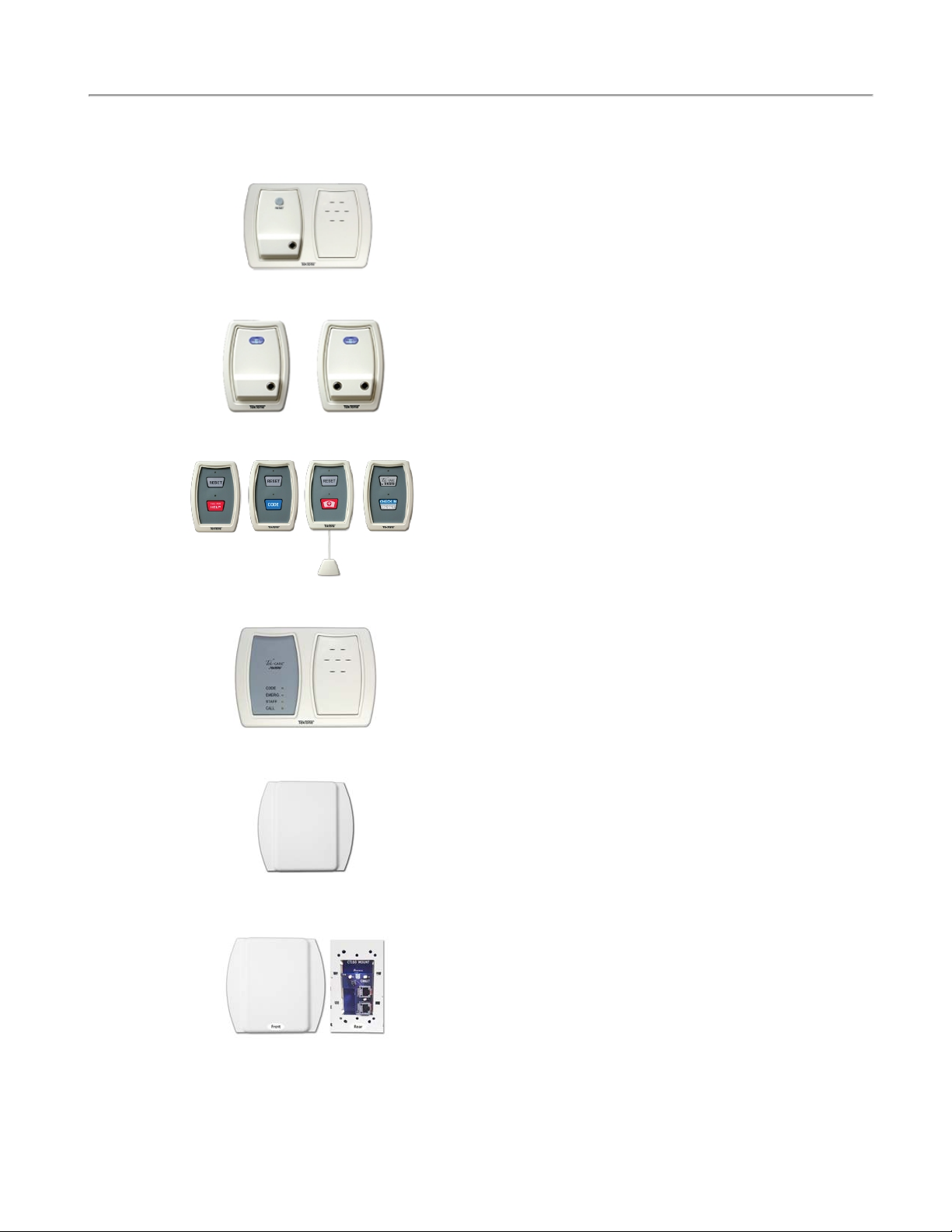
IR160 Audio Station: The IR160 Audio Station provides a speaker and
microphone for two-way communication between facility staff and res-
idents. The IR160 requires a connection to the LI122UN Room Controller
(using one point) and a connection to the Tek-CARE160 Audio Bus cable.
The IR160 Audio Station can be installed as a standalone speaker, but is
most commonly installed with an SF121 or an SF123 series station in an
IH122K dual gang housing. The IR160 shown to the left is shown with a
SF121 Patient Station.
SF121 and SF122 Patient Stations: The SF121 Patient Station is designed
to provide a single 1/4" jack for standard call cords. The SF121 mounts
near a resident’s bed or chair, and enables calls to be placed using push-
button call cords, geriatric call cords, pneumatic call cords, and more. The
SF121 is equipped with an illuminated reset button. The SF122 Patient Sta-
tion is a dual-jack version of the SF121.
SF123 Customizable 2-Button Pull-Cord Station: The SF123 station is
used to place a variety of calls on the Tek-CARE160 system. The SF123
uses interchangeable inserts depending on the desired function of the sta-
tion. The SF123 is most commonly used as an Emergency station, but can
be easily configured for Bath, Code Blue, and Emergency 2 calls. Custom
call types may also be created, and custom call type inserts can be gen-
erated using the LS450 ConfigTool software. The SF123 can also be used
as a room-level reset button and a check-in station. Use the RP187K Gasket
Kit for mounting in wet environments.
SF125 Duty Station: The SF125 is a duty station used to alert staff to
pending Tek-CARE160 system calls. The duty station is installed in areas
where call annunciation is needed, but the full functionality of a master sta-
tion is not. Four LEDs communicate the type of active call, and an audible
tone alerts staff members when calls are placed. The SF125 duty station
uses two points on the LI122UN Room Controller or PM120 Room Con-
troller.
PM123 Auxiliary Input Module: The PM123 is a module used to monitor
normally open dry contacts such as door switches, emergency pushbuttons,
and alarm contact outputs. The PM123 is designed to be installed out of
sight. Up to two individual contacts can be monitored with a single PM123.
The PM123 may also be used as an auxiliary check-in device. Normally
open contacts such as door switches, motion detectors, or pressure pads
may be used with the PM123 to satisfy a resident check-in requirement on
the system.
CT160 Cable Adapter (CT160K pictured - CT160 with housing): The
CT160 is designed to adapt a connection from a two-wire flying lead to an
8P8C connector. The CT160 may be connected to LI122UN and PM120
Room Controllers or can be ordered as the CT160K which includes hous-
ing.
6|IL1024 Tek-CARE160 Installation Manual Copyright ©TekTone Sound and Signal Mfg., Inc. All Rights Reserved

SF126DC Dry Contact Output Module: The Normally Open (N.O.) Dry
Contact Output Module provides a two-pin header for a relay/device con-
nection and another for the station connection. Upon initiation it will
provide one of four programmable output behaviors; from the master sta-
tion, either a 5-second on or a toggle on/off output, or at the station, a local
or zone output. The SF126DC can be mounted individually or with another
SF120 peripheral, depending on the application.
Copyright ©TekTone Sound and Signal Mfg., Inc. All Rights Reserved IL1024 Tek-CARE160 Installation Manual |7
Introduction and Overview

Installation
Installation
Installation for the Tek-CARE160 system is designed to be very straightforward. The data bus is designed
to operate on unshielded 18/2 AWG twisted cable or on CAT5e or better cabling. The audio bus is designed
to operate on CAT5e or better cabling.
When making wiring connections, use quality crimp connectors such as Dolphin®Super B®connectors.
Do not use wire nuts. Adequately protect all splices using junction boxes.
Installation Workflow:
oInstall all NC160 CEModules.
oInstall the backup batteries.
oRun data and audio bus wiring through the facility.
oInstall and address LI122UN/PM120 Room Controllers.
oConnect the audio bus to IR160 stations.
oRun master bus wiring and make 8P8C terminations.
oCheck data bus for shorts and connect master and data bus wiring to the NC160 CEModule.
oPower on the NC160 CEModule.
oCreate a configuration using the LS450 ConfigTool software.
oTest the Tek-CARE160 system.
oBack up the configuration and turn the system over to the facility.
Types of Installation
There are two types of installations available for the Tek-CARE160 system, a One-to-One installation and a Cus-
tom installation.
One-to-One
A one-to-one installation strategy involves installing a single LI122UN Room Controller outside of each
room in the facility and using the points on that room controller to connect to stations installed in that
room.
In this installation strategy, stations are normally wired to their default points on the room controller. The
room controller will then annunciate calls from its attached stations only.
Custom
In a custom installation, each point on a room controller can be reassigned to a unique Station ID. This
enables the room controller to drive stations installed in different rooms. A custom installation strategy also
enables a single room controller to drive multiple patient stations in a single area, such as a ward.
NOTE: Custom installations require training and a ConfigTool Plus or ConfigTool Elite
license.
8|IL1024 Tek-CARE160 Installation Manual Copyright ©TekTone Sound and Signal Mfg., Inc. All Rights Reserved

Installation Concerns
When installing the Tek-CARE160 system, organization is key. As you install the system, note the DIP
switch address of each room controller, the physical location of the room controller, and which stations are
connected to the room controller on each point.
Keeping detailed records throughout the installation process will greatly simplify system programming and
setup. A programming worksheet is included at the end of this manual.
Below is an example of a completed programming worksheet.
Power Considerations
In order to stay within the power limits of the NC160 CEModule and ensure reliable system performance,
the Tek-CARE160 Power Calculator will calculate the master load for the module. The calculate may be
downloaded at:
http://www.tektone.com/pdf_files/GEN2_master_station_load_value_calculator.xlsx
Copyright ©TekTone Sound and Signal Mfg., Inc. All Rights Reserved IL1024 Tek-CARE160 Installation Manual |9
Installation

Installation
Figure 1 - NC160 CEModuleConnections
10|IL1024 Tek-CARE160 Installation Manual Copyright ©TekTone Sound and Signal Mfg., Inc. All Rights Reserved

The NC160 Central Equipment Module
The NC160 Central Equipment Module contains all necessary connections for the Tek-CARE160 hardware
as well as the backup batteries for the system. The NC160 CEModule is designed to be mounted in a stand-
ard 19" server rack using included CL120RM brackets. Modules may also be desk-mounted and stacked.
The NC160 CEModule requires 120VAC or 240VAC power, and must be connected to a generator-backed
circuit intended for life safety equipment.
If the NC160 CEModule is not mounted in a server rack, allow adequate air space around the front, sides,
and back of the unit. At least 6" of airspace must be maintained for the unit to operate reliably. Refer to Fig-
ure 1 on page 10 for NC160 CE port descriptions.
On the front of the NC160 CEModule, you will find a bank of DIP switches. These DIP switches are used
to configure various options on the CE module and to provide an address for the CE module.
The two-position DIP switch indicated by the STA/LOC is for future use, and both DIP switches should be
turned OFF. If either switch is turned on when the module boots up, the NC160 CEModule will return an
LED error code 30 (PORT_MODE_NOT_SUPPORTED). The yellow and red LEDs will be lit, and the
green LED will flash a two-digit code.
The small bank of 4 DIP switches on the left is used for the following functions. Note that the down pos-
ition of the switch is on. Normal settings are indicated in parenthesis.
Figure 2 - Module DIP Switch Addressing
Copyright ©TekTone Sound and Signal Mfg., Inc. All Rights Reserved IL1024 Tek-CARE160 Installation Manual |11
Installation

Installation
Switch 1 – Redefault the database. (Off/Up)
Switch 2 – Silence the audio alarm buzzer. (On/Down)
Switch 3 – Redefault network subnet assignment to 192.168.1. (Off/Up)
Switch 4 – Factory and troubleshooting use only. (Off/Up)
The second bank of 8 DIP switches is used to set the address of the NC160 CEModule.
Switch 1 – Switch 7 – Used to select the CE module’s address. Valid addresses are 1-75. Note that though
there are 75 available DIP switch addresses, no more than 20 modules may be installed on a single Tek-
CARE system. Switch 1- Switch 7 utilize standard binary addressing, with Switch 1 being 1 and Switch 7
being 64.
Switch 8 – Factory Use Only. (Leave turned Off/Up)
Install Backup Batteries
Before proceeding with system setup, install the backup batteries in the module. Open the two-battery com-
partment covers on the top of the module.
Locate the red (positive) and black (negative) wires with female spade connectors under each door. Move
the wires out of the way and place the batteries in the holders and connect the spade terminals to the bat-
teries as shown below.
Connect the red leads to the positive terminal of each battery and the black leads to the negative terminal of
each battery.
Figure 3 - Battery Connections
The Tek-CARE160 Data Bus
The Tek-CARE160 data bus is a two-wire serial communications bus. There are four ports on the front of
the module, each capable of driving up to 1,000 feet of data bus and up to 16 LI122UN Room Controllers.
There are four 8P8C jacks on the front of the module. The two on the right are for NC415G3/NC404TS
Master Stations, and two on the left for Tek-CARE Network connectivity. Each module supports up to six
master stations, three per port.
To begin installing the NC160 CEModule, mount the module either on a server rack or on a shelf. Plug in
the supplied AC power cord, and turn the unit on. You are now ready to begin connecting field wiring to
the module.
12|IL1024 Tek-CARE160 Installation Manual Copyright ©TekTone Sound and Signal Mfg., Inc. All Rights Reserved

Tek-CARE160 Installation Considerations
Note that the audio bus on the Tek-CARE160 system is analog, and thus, only supports one concurrent
audio connection per port.
For example, if a facility has IR160 stations in rooms 100-110 connected to Port 0 and rooms 111-160 con-
nected to port 1, one NC415G3/NC404TS Master Station could connect audio to room 100 and another
NC415G3/NC404TS Master Station could connect audio to room 111. If a master station attempts to con-
nect to an audio bus that is already in use, the connection will fail.
When installing cabling, be sure to keep the audio bus and the data bus for each port together. Remember
that the IR160 requires a connection to the room controller and the audio bus. If the IR160 is connected to a
room controller that uses Data Bus Port 0, but the audio bus for that IR160 connects to Port 1, the audio
connection will not function.
Figure 4 - Audio Bus and Controller Connections
Copyright ©TekTone Sound and Signal Mfg., Inc. All Rights Reserved IL1024 Tek-CARE160 Installation Manual |13
Installation

Installation
Figure 5 - Typical Room with One IR160 Audio Station
Figure 8: Typical Room with one IR160 Audio Sta-
tion
14|IL1024 Tek-CARE160 Installation Manual Copyright ©TekTone Sound and Signal Mfg., Inc. All Rights Reserved

Audio Connection Considerations
The most common scenario for installing the Tek-CARE system is to have a single IR160 Audio Station
associated with a single room controller, and thus, a single Station ID.
Up to four IR160 Audio Stations may be associated with a single Station ID; however, all IR160s asso-
ciated with a Station ID will open their audio connections simultaneously.
Example 1
In the example shown in Figure 5 on page 14, a single LI122UN room controller is installed outside of the
room. An SF122 is connected to Point 1, an SF123 is connected to Point 4 (creating a Bath call) and an
IR160 is connected to Point 6. Note that the audio cable never connects to the room controller.
In this example, all three stations are associated with a single Station ID, meaning that any call from this
Station ID (SF122 or SF123) is answered at the master station, the audio channel opens.
Example 2
The example shown in Figure 6 on page 17 illustrates a slightly different wiring scheme utilizing the same
room layout. In this example, everything is the same as before except there is an additional IR160 installed
in the bathroom. Again, in this scenario, all four stations are connected to a single room controller, and asso-
ciated with a single Station ID.
In this scenario, a call from either the SF122 Patient Station or the SF123 Bath Station will open audio to
both IR160 stations. This scenario requires that the system be manually configured to expect an IR160 con-
nected to Point 5.
Example 3
If unique audio in each location is desired, a Plus or Elite license is required for the LS450 ConfigTool Soft-
ware. This enables the points of one controller to be assigned to different Station IDs.
Returning to Figure 6 on page 17, if the facility requires unique audio connections at both the bed and the
bath areas, simply assign Points 1 and 6 of the room controller to a Station ID (e.g., RM 100) and the other
two points to a different Station ID (e.g., 100 BATH).
Once the points have been reassigned, answering calls or dialing each Station ID will only open audio at
the IR160 that is associated with that Station ID.
Copyright ©TekTone Sound and Signal Mfg., Inc. All Rights Reserved IL1024 Tek-CARE160 Installation Manual |15
Installation

Installation
Wiring Installation
Tek-CARE160 Data Bus Wiring
The main wiring for the Tek-CARE160 system consists of a two-wire communications data bus. The data
bus ports on the front of the NC160 CEModule are capable of supporting 16 room controllers each, for a
total of 64 controllers per module. Note that each port is capable of driving up to 1,000' of cable for the
data bus. TekTone recommends 18/2 stranded cable for the data bus, but other types of wiring are accept-
able. See the table below for details.
NOTE: If 22 AWG cable is used, the data bus runs can be extended by twisting conductors
together at each splice. For example, 22/4 cable used for data bus wiring could have two con-
ductors twisted together for the positive leg of the data bus and two conductors twisted
together for the negative leg.
16 Controllers
Max
12 Controllers
Max
8 Controllers
Max
8 Controllers
Max
18 AWG Cable 1000' 1000' 1000' 1000'
20 AWG Cable 625' 800' 1000' 1000'
22 AWGCable 350' 525' 750' 1000'
2 x 22 AWG Cable 775' 1000' 1000' 1000'
CAT5e with CT160 1000' 1000' 1000' 1000'
CAT5e Cabling Option
The CT160 is convenient for wiring from a module to room controllers. From the NC160CE, connect the
CT160 two-wire pigtail to the data bus on the port. Refer to Figure 1 on page 10. CT160 can either be
installed as a standalone with the mounting hardware (CT160K), or it can be snapped into the back of
LI122UN dome lights and/or PM120 controller modules. Once installed, run or reuse CAT5e or better
cable plugged into the CT160 and out to each dome or module. Refer to Figure 7 on page 19 to note the
positive and negative connections. Test CAT5e connections and meter cables for shorts and incorrect wir-
ing to avoid issues later.
16|IL1024 Tek-CARE160 Installation Manual Copyright ©TekTone Sound and Signal Mfg., Inc. All Rights Reserved

Figure 6 - Typical Room with two IR160 Audio Stations
Copyright ©TekTone Sound and Signal Mfg., Inc. All Rights Reserved IL1024 Tek-CARE160 Installation Manual |17
Installation

Installation
Run wiring from room controller to room controller and connect the room controllers to the data bus in par-
allel using T-taps. Connect the positive wire in the data bus cable to the solid white wire (pin 13) on the
back of the room controller, and connect the negative wire from the data bus to the black wire (pin 14) on
the room controller.
NOTE: If using CAT5e cable, make sure to use the appropriate terminators and 8P8C con-
nectors.
Tek-CARE160 Audio Bus Wiring
The audio bus for the Tek-CARE160 system is designed to operate on CAT5e or better cable.
Maximum audio bus cabling distance, including drops to IR160 Audio Stations, must not exceed 1,000' on
each available port. Each IR160 station must be connected to the audio bus.
TekTone recommends pairing up an audio bus cable and data bus cable. For example, the data bus cable
from port 0A should be paired with the audio bus cable from port 0A. These cables should be pulled
together. Do not use a 4-conductor cable to combine the audio and data bus. This will produce
extreme audio interference and drastically impact audio quality.
IMPORTANT: Use care when running audio bus cable. If possible, avoid running the audio
bus cable near high voltage electrical cables. Also, try to neatly install the audio cable, avoid-
ing intertwining it with the data bus cabling.
An IR160 Audio Station will open an audio connection when a call placed by any SF121, SF122, SF123, or
PM123 assigned to the same Station ID as the IR160 is answered at a master station.
If a Station ID is dialed from the master station, an audio connection will be opened on all IR160s asso-
ciated with that Station ID.
Addressing Room Controllers and Default Behavior
The Tek-CARE160 system is designed to be simple to install. As such, the room controllers are designed so
that a basic system can be brought online with minimal programming.
Each room controller must be addressed to communicate on the data bus using the five position DIP switch
found on the back of the room controller. Available addresses are 0-31.
When assigning addresses to the room controllers, keep in mind which port the room controller is con-
nected to. For purposes of addressing, the two left data bus ports (0A and 0B) and two right data bus ports
(ports 1A and 1B) are tied together. This means that addresses for room controllers connected to port 0A
and port 0B must be unique, but port 0A and port 1A may have addresses duplicated between them.
Keep detailed notes of the physical addresses and locations of room controllers installed in the facility
using the worksheet in the back of this manual. Without adequate installation notes, system configuration
will be extremely time consuming.
NOTE: No terminating jumper or resistor is required on the data bus. If necessary, the data
bus may also be installed using a star topology. Do not exceed 1,000 feet of cable on any
one data bus run.
The address assigned to the room controller also influences the default behavior of the room controller. If a
controller is addressed as 0-29, the system assumes that the controller will be installed in a single bed con-
figuration. This is useful for simple one-to-one installations. Room controllers addressed as 30-31 are
defaulted to duty station behavior. These default behaviors are modified during configuration setup if
needed.
18|IL1024 Tek-CARE160 Installation Manual Copyright ©TekTone Sound and Signal Mfg., Inc. All Rights Reserved

Connect Stations
Up to six stations may be connected to each room controller using the header on the back of the room con-
troller. The leads on the header are paired together to form a point on the room controller. This means that
each header has six points to connect stations to, and one point for data bus connections.
With the wire leads on the connector pointing down, Point 1 is on the left. The illustration below shows the
six available points on the header. The point connections are arranged +-, +-, etc., with each group of +-
connections making up one point.
Points Table
Figure 7 - Single Patient Station Default Room
Copyright ©TekTone Sound and Signal Mfg., Inc. All Rights Reserved IL1024 Tek-CARE160 Installation Manual |19
Installation

Installation
Figure 8 - Double Patient Station Default Room
Figure 9 - Duty Station Default Room Controller Points (Address 30-31)
Tek-CARE160 Station Wiring
When installing wiring to stations, use 22-18 AWG cable. Do not exceed 100 feet of cabling for SF121,
SF122, and SF123 stations. For SF125 stations, do not exceed 50 feet of cabling. Only one station may be
connected to each point. Do not splice multiple stations together on the same point wiring.
One-to-One Installations
In most installations, one room controller will be used as a connection point for all of the station in the asso-
ciated room. This provides the simplest software configuration option, but other installation strategies are
available.
In a one-to-one installation, connect the stations to the room controller according to the Points Table on
page 19.
Figure 10
FigFigure
ure 9: SF123
Assembly
Diagram
20|IL1024 Tek-CARE160 Installation Manual Copyright ©TekTone Sound and Signal Mfg., Inc. All Rights Reserved
Other manuals for Tek-CARE160
1
Table of contents
Other TekTone Medical Equipment manuals
Popular Medical Equipment manuals by other brands

biodex
biodex 058-800 Operation manual

Dräger
Dräger Babylog VN500 Disassembly/Assembly and Reprocessing

mbnet Engineering
mbnet Engineering ergo vac operating manual

Haemonetics
Haemonetics Cell Saver Elite User manual addendum

Erbe
Erbe ICC 200 instruction manual

POLYDENTIA
POLYDENTIA myRing Forte Cleaning, disinfection & sterilization guide