Atmel AT88RF1354 Operating manual

AT88RF1354
Command
Reference Guide
5150B—RFID—4/09


Table of Contents
Section 1 Introduction............................................................................................................................... 1-1
1.1 Product Description ..................................................................................................... 1-1
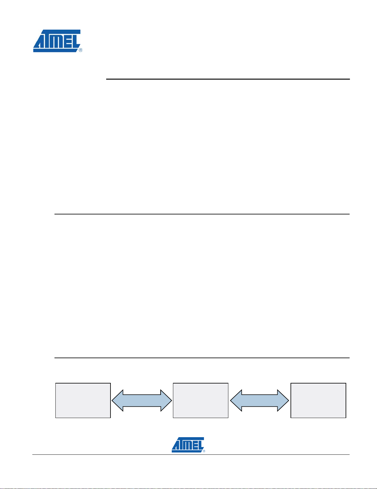
1.2 System Diagram .......................................................................................................... 1-1
1.3 Scope........................................................................................................................... 1-2
1-2
1-3
1-4
1-5
2-2
2-3
2-4
2-8
2-11
2-13
2-15
2-16
2-17
2-18
2-23
3-3
3-4
3-6
3-7
3-8
3-9
3-10
3-11
1.4 Conventions.................................................................................................................
1.4.1 SPI Command Format....................................................................................
1.4.2 TWI Command Format ...................................................................................
1.4.3 ACK/NACK Response Byte............................................................................
Section 2 Instruction Set .......................................................................................................................... 2-1
2.1 Abort Command [$0D].................................................................................................
2.2 Clear Command [$0E].................................................................................................
2.3 Poll Continuous Command [$02].................................................................................
2.4 Poll Single Command [$01].........................................................................................
2.5 Read Buffer Command [$08].....................................................................................
2.6 Read Register Command [$07].................................................................................
2.7 RF OFF Command [$0B]...........................................................................................
2.8 RF ON Command [$0A].............................................................................................
2.9 Sleep Command [$0C] ..............................................................................................
2.10 TX Data Command [$03]...........................................................................................
2.11 Write Buffer Command [$09].................................................................................... 2-21
2.12 Write Register Command [$06] ................................................................................
Section 3 Register Summary.................................................................................................................... 3-1
3.1 CPR0 Register [$00 / $01]...........................................................................................
3.2 CPR Registers 1, 2, 3, 4..............................................................................................
3.3 SREG Register [$0A]...................................................................................................
3.4 EREG Register [$0B]..................................................................................................
3.5 IDR Register [$0C].......................................................................................................
3.6 PLL Register [$0D] ......................................................................................................
3.7 TXC Register [$0E]....................................................................................................
3.8 RXC Register [$0F]....................................................................................................
Appendix A Initialization Procedure.........................................................................................................A-1
Appendix B The SPI Serial Interface.........................................................................................................B-1
Appendix C The TWI Serial Interface........................................................................................................C-1
Appendix D Index .......................................................................................................................................D-1
D.1 Figure Index.................................................................................................................D-1
D.2 Table Index..................................................................................................................D-1
D.3 Revision History...........................................................................................................D-3
AT88RF1354 Command User Guide i
5150B—RFID—4/09


AT88RF1354 Command User Guide
Section 1
Introduction
Features
AT88RF1354 Instruction Set
AT88RF1354 Register Definitions
Initialization Procedure
Description
This document describes the instruction set and register definitions for the AT88RF1354 13.56 MHz
ISOI/IEC 14443 Type B Reader IC. Device initialization examples are included for reference by the
software developer or embedded systems programmer using this RF reader.
This specification is formatted as a reference document, with each command description and
register definition on a separate page. The related definitions and data field requirements are
located on the same page for ease of use.
1.1 Product Description
The AT88RF1354 is a smart, high performance ISO/IEC 14443 Type B RF Reader IC. The
AT88RF1354 communicates with RFID Transponders or Contactless Smartcards using the industry
standard ISO/IEC 14443-2 Type B signal modulation scheme and ISO/IEC 14443-3 Type B frame
format. Data is exchanged half duplex at a 106k bit per second rate. A two byte CRC_B provides
communication error detection capability.
The AT88RF1354 is compatible with 3.3 V and 5 V host microcontrollers with two-wire or SPI serial
interfaces. In two-wire interface mode the AT88RF1354 operates as a TWI slave and requires four
microcontroller pins for data communication and handshaking. In SPI interface mode the
AT88RF1354 operates as a mode 0 SPI slave and requires six microcontroller pins for data
communication and handshaking.
To communicate with an RFID transponder the host microcontroller sends a data packet for
transmission over the RF communications channel, and receives the response data packet that is
received from the transponder over the RF communications channel. AT88RF1354 performs all RF
communication packet formatting, decoding, and communication error checking. The host
microcontroller is not burdened with RF encoding, timing, or protocol functions since these tasks
are all performed by the AT88RF1354.
1.2 System Diagram
Figure 1. Communications in an RFID System
Serial Interface
RF Communications
Host
Microcontroller CardReader IC
1-1
5150B—RFID—4/09

AT88RF1354 Command Reference Guide
1-2 AT88RF1354 Command User Guide
5150B—RFID—4/09
1.3 Scope
This AT88RF1354 Command Reference Guide document includes all command and register
information for the AT88RF1354 RF Reader. The RF Reader electrical specifications are described
in the AT88RF1354 Specification document. Reference Designs and additional technical
information is available in AT88RF1354 Application Notes and Other Documents. See
www.atmel.com
1.4 Conventions
ISO/IEC 14443 nomenclature is used in this document where applicable. The following terms and
abbreviations are utilized throughout this document. Additional terms are defined in the section in
which they are used.
Card: A Contactless Smart Card or RFID Tag in proximity to the reader antenna.
Host: The microcontroller connected to the serial interface of the reader IC.
PCD: Proximity Coupling Device – is the host and reader with antenna.
PICC: Proximity Integrated Circuit Card – is the tag/card containing an IC and antenna.
Reader: The AT88RF1354 Integrated Circuit with loop antenna and associated circuitry
RFU: Reserved for Future Use – is any feature, memory location, or bit that is held as
reserved for future use by the ISO standards committee or by Atmel.
$ xx: Hexadecimal Number – denotes a hex number “xx” (Most Significant Bit on left).
xxxx b: Binary Number – denotes a binary number “xxxx” (Most Significant Bit on left).
See Atmel Application Note Understanding the Requirements of ISO/IEC 14443 for Type B
Proximity Contactless Identification Cards at www.atmel.com for detailed information regarding the
ISO/IEC 14443 RF communication protocol.

AT88RF1354 Command Reference Guide
AT88RF1354 Command User Guide 1-3
5150B—RFID—4/09
1.4.1 SPI Command Format
Figure 2. Serial Communications with the SPI Interface
Host Reader
Command > $00
Address
PARAM1
$0 N
Data0
Wait for ISTAT
ISTAT goes High
Response > ACK/NACK
Data0
Data1
Z $4
$FF
ISTAT stays Low
Each SPI serial interface command / response exchange between the Host microcontroller and
AT88RF1354 is formatted as shown above in Figure 2. The bytes are shown in the order in which
they are transmitted, with Host transmissions in the left column, and Reader transmissions in the
right column. Blue text is used for notes regarding the ISTAT serial interface handshaking signal.
Each byte contains one or more fields as indicated by lines drawn vertically within the byte. The
field in the left half of the byte is the upper nibble of the byte, and the field to the right is the lower
nibble of the byte. In Figure 2, four fields contain values ($00, $0, $4, $FF), eight fields contain field
names (“Address”, “PARAM1”, “N”, “Data0”, “ACK/NACK” “Data1”, “Z”). Any field name containing
the word “register” indicates an IC register value.

AT88RF1354 Command Reference Guide
1-4 AT88RF1354 Command User Guide
5150B—RFID—4/09
1.4.2 TWI Command Format
Figure 3. Serial Communications with the TWI Interface
Host Reader
TWI Address > TWI_W
Command > $00
Address
PARAM1
$0 N
Data0
Wait for ISTAT
ISTAT goes High
TWI Address > TWI_R
Response > ACK/NACK
Data0
Data1
Z $4
$FF
ISTAT stays Low
Each TWI serial interface command / response exchange between the Host microcontroller and
AT88RF1354 is formatted as shown in Figure 3. The bytes are shown in the order in which they
are transmitted, with Host transmissions in the left column, and Reader transmissions in the right
column. Blue text is used for notes regarding the ISTAT serial interface handshaking signal.
Each byte contains one or more fields as indicated by lines drawn vertically within the byte. The
field in the left half of the byte is the upper nibble of the byte, and the field to the right is the lower
nibble of the byte. In Figure 3, four fields contain values ($00, $0, $4, $FF), ten fields contain field
names (“TWI_W”, “Address”, “PARAM1”, “N”, “Data0”, “TWI_R”, “ACK/NACK” “Data1”, “Z”). Any
field name containing the word “register” indicates an IC register value.
The “TWI_W” and “TWI_R” fields contain the Two Wire Interface device address of the
AT88RF1354 Reader with either the read (TWI_R) or write (TWI_W) bit set. Note that TWI ACK
polling is not supported by the AT88RF1354.

AT88RF1354 Command Reference Guide
AT88RF1354 Command User Guide 1-5
5150B—RFID—4/09
TWI Device Address
The TWI device address is selected with the ADDR address select pin of the AT88RF1354.
Table 1. TWI Device Address
TWI Device Address
ADDR
Pin Bit 6 Bit 5 Bit 4 Bit 3 Bit 2 Bit 1 Bit 0 TWI_R TWI_W
Vss 0 1 0 1 0 0 0 $51 $50
Vcc 1 1 0 1 0 1 0 $D5 $D4
All other values are NOT supported
1.4.3 ACK/NACK Response Byte
The first byte of each response is usually an ACK/NACK byte which indicates if the requested
operation succeeded or failed. The bit definitions for the ACK/NACK byte are shown in Figure 4
and Figure 5. This response byte contains 6 bits from the Error Register, and 2 bits which indicate
the success or failure of the requested operation. 01b in the least significant bits is an ACK,
indicating success. 10b in the least significant bits is a NACK, indicating failure. The contents of the
error register are not relevant to non-RF commands and can be ignored.
Figure 4. ACK/NACK Byte Format for ACK Response
Bit 7 Bit 6 Bit 5 Bit 4 Bit 3 Bit 2 Bit 1 Bit 0
CRC FRAME BYTE TIME COL SPE 0 b 1 b
Error Register Bits ACK
Figure 5. ACK/NACK Byte Format for NACK Response
Bit 7 Bit 6 Bit 5 Bit 4 Bit 3 Bit 2 Bit 1 Bit 0
CRC FRAME BYTE TIME COL SPE 1 b 0 b
Error Register Bits NACK
The three RF communication commands Poll Continuous, Poll Single, and TX Data return the Error
Register contents in the first byte of the response. Figure 6 shows the Error Register format.
Figure 6. Error Register Format in RF Command Responses
Bit 7 Bit 6 Bit 5 Bit 4 Bit 3 Bit 2 Bit 1 Bit 0
CRC FRAME BYTE TIME COL SPE 0 b 0 b


AT88RF1354 Command User Guide 2-1
Section 2
Instruction Set
Table 2. Instruction Set Sorted by Command Name
Command Name Description Code
Abort Exit Command in Progress $0D
Clear Exit Command in Progress, Clear Buffer, Turn RF OFF $0E
Poll Continuous Poll Continuously for Type B PICCs $02
Poll Single Poll Once for Type B PICCs $01
Read Buffer Read Data Buffer $08
Read Register Read Configuration Register $07
RF OFF Turn Off 13.56 MHz RF Field $0B
RF ON Turn On 13.56 MHz RF Field $0A
Sleep Activate Standby Mode $0C
TX Data Transmit Data to PICC and Receive the Response $03
Write Buffer Write Data Buffer $09
Write Register Write Configuration Register $06
All other command code values are NOT supported
Commands in the following sections are listed in alphabetical order.
5150B—RFID—4/09

AT88RF1354 Command Reference Guide
2-2 AT88RF1354 Command User Guide
5150B—RFID—4/09
2.1 Abort Command
This command aborts a command in progress and places the reader in the idle state.
2.1.1 SPI Command Format
Host Reader
Command > $0D
Wait for ISTAT
ISTAT goes High
Response > ACK/NACK
ISTAT stays Low
2.1.2 TWI Command Format
Host Reader
TWI Address > TWI_W
Command > $0D
Wait for ISTAT
ISTAT goes High
TWI Address > TWI_R
Response > ACK/NACK
ISTAT stays Low
2.1.3 Operation
The Abort command stops a command operation in progress. The contents of the RAM buffer and
registers are not modified by the Abort command.
2.1.4 Command Field Description
There are no field options in this command.
2.1.5 Response Field Descriptions
ACK: Acknowledge — the command executed correctly
NACK: Not Acknowledge — the command did not execute correctly

AT88RF1354 Command Reference Guide
AT88RF1354 Command User Guide 2-3
5150B—RFID—4/09
2.2 Clear Command [$0E]
This command aborts a command in progress, turns off the RF field, clears the RAM buffer, and
places the reader in the idle state.
2.2.1 SPI Command Format
Host Reader
Command > $0E
Wait for ISTAT
ISTAT goes High
Response > ACK/NACK
ISTAT stays Low
2.2.2 TWI Command Format
Host Reader
TWI Address > TWI_W
Command > $0E
Wait for ISTAT
ISTAT goes High
TWI Address > TWI_R
Response > ACK/NACK
ISTAT stays Low
2.2.3 Operation
The Clear command stops a command in progress, turns off the RF field, and clears the RAM
buffer. The contents of the error register are reset by the Clear command, the contents of the other
registers are unchanged.
2.2.4 Command Field Descriptions
There are no field options in this command.
2.2.5 Response Field Descriptions
ACK: Acknowledge — the command executed correctly
NACK: Not Acknowledge — the command did not execute correctly

AT88RF1354 Command Reference Guide
2-4 AT88RF1354 Command User Guide
5150B—RFID—4/09
2.3 Poll Continuous Command [$02]
This command performs multiple Type B polling sequences to detect cards near the antenna.
The first response is returned to the host. In the event a card response containing a
communication error is received, then an error code is returned. If no response is detected, then
polling continues until an Abort command is sent by the host.
The optional Smart Poll mode modifies the polling operation to include error tolerance. In Smart
Poll mode polling continues until an error free card response is received.
2.3.1 SPI Command Format
Host Reader
Command > $02
AFI
PARAM
Wait for ISTAT
ISTAT goes High
Success Response > Error Reg
ATQB 1
ATQB 2
ATQB 3
ATQB 4
ATQB 5
ATQB 6
ATQB 7
ATQB 8
ATQB 9
ATQB 10
ATQB 11
ATQB 12
ISTAT stays Low
OR ISTAT goes High
Failure Response > Error Reg
ISTAT stays Low

AT88RF1354 Command Reference Guide
AT88RF1354 Command User Guide 2-5
5150B—RFID—4/09
2.3.2 TWI Command Format
Host Reader
TWI Address > TWI_W
Command > $02
AFI
PARAM
Wait for ISTAT
ISTAT goes High
TWI Address > TWI_R
Success Response > Error Reg
ATQB 1
ATQB 2
ATQB 3
ATQB 4
ATQB 5
ATQB 6
ATQB 7
ATQB 8
ATQB 9
ATQB 10
ATQB 11
ATQB 12
ISTAT stays Low
OR ISTAT goes High
TWI Address > TWI_R
Failure Response > Error Reg
ISTAT stays Low

AT88RF1354 Command Reference Guide
2-6 AT88RF1354 Command User Guide
5150B—RFID—4/09
2.3.3 Operation
The functionality of the Poll Continuous command is identical to the Poll Single command, except
that after the final Slot-MARKER is sent, if no card response is received, the reader chip repeats
the polling procedure. The Poll Continuous command is like an infinite loop of Poll Single
commands that is broken when a card response (good or bad) is received.
This command performs multiple polling sequences with “N” slots using the ISO/IEC14443-3 Type
B commands REQB, WUPB, and Slot-MARKER. The CPR0 default Communication Protocol
settings are used by this command.
A polling sequence consists of either an REQB or WUPB command, followed by the number of
Slot-MARKER commands indicated by “N”. When a response is received, then the polling
sequence is stopped and the response is returned to the host. When a communication error is
detected, then the polling sequence is stopped and an error code is returned to the host.
2.3.4 Smart Poll Mode Operation
Smart Poll mode is enabled by sending the Poll Continuous command with N = 111b. In the Smart
Poll mode, the reader will continually send REQB/WUPB with N = 000b until it receives a card
response. If this response is valid, it will return the response to the host. If the card response
generates a communication error, the reader assumes that there was a collision. It will then send
the next REQB/WUPB with N = 001b, and if there is no valid card response it will send Slot-
MARKER for slot two.
If there is no response from a card in either slot, then the reader returns to polling with N = 000b. If
there is an error free card response, then it will be returned to the host. If there is another collision
and no valid response, however, N will again be incremented, and the reader will send the correct
sequence of REQB/WUPB and Slot-MARKERs. In the case where Smart Poll mode reaches 16
slots and only collisions are detected, then polling is stopped, and a Smart Poll error code is
returned to the host. If no error-free card response is detected, then polling continues until an Abort
command is sent by the host.
2.3.5 Command Field Descriptions
AFI: AFI code to be sent by reader in the polling command. To search for all cards set
AFI = $00.
PARAM: Contains Polling command control fields: R/W and N.
Figure 7. PARAM Byte Field Definitions. Poll Continuous Command
Bit 7 Bit 6 Bit 5 Bit 4 Bit 3 Bit 2 Bit 1 Bit 0
RFU R/W N
R/W: Polling command
Table 3. REQB/WUPB Selection Bit Coding in the PARAM Byte.
Bit 3 Command
0 REQB
1 WUPB
N: Code for number of slots to poll for cards

AT88RF1354 Command Reference Guide
AT88RF1354 Command User Guide 2-7
5150B—RFID—4/09
Table 4. Coding of N, number of slots to poll.
Bit 2 Bit 1 Bit 0 N
0 0 0 1
0 0 1 2
0 1 0 4
0 1 1 8
1 0 0 16
1 0 1 RFU
1 1 0 RFU
1 1 1 Smart
RFU: Reserved for Future Use. All RFU bits must contain 0 b.
2.3.6 Response Field Descriptions
Error Register Contents: $00 indicates no errors.
ATQB: Answer to the polling command received from the PICC.

AT88RF1354 Command Reference Guide
2-8 AT88RF1354 Command User Guide
5150B—RFID—4/09
2.4 Poll Single Command [$01]
This command performs a single Type B polling sequence to detect cards near the antenna. The
first response is returned to the host. In the event no error free response is detected, then an error
code is returned.
2.4.1 SPI Command Format
Host Reader
Command > $01
AFI
PARAM
Wait for ISTAT
ISTAT goes High
Success Response > Error Reg
ATQB 1
ATQB 2
ATQB 3
ATQB 4
ATQB 5
ATQB 6
ATQB 7
ATQB 8
ATQB 9
ATQB 10
ATQB 11
ATQB 12
ISTAT stays Low
OR ISTAT goes High
Failure Response > Error Reg
ISTAT stays Low

AT88RF1354 Command Reference Guide
AT88RF1354 Command User Guide 2-9
5150B—RFID—4/09
2.4.2 TWI Command Format
Host Reader
TWI Address > TWI_W
Command > $01
AFI
PARAM
Wait for ISTAT
ISTAT goes High
TWI Address > TWI_R
Success Response > Error Reg
ATQB 1
ATQB 2
ATQB 3
ATQB 4
ATQB 5
ATQB 6
ATQB 7
ATQB 8
ATQB 9
ATQB 10
ATQB 11
ATQB 12
ISTAT stays Low
OR ISTAT goes High
TWI Address > TWI_R
Failure Response > Error Reg
ISTAT stays Low

AT88RF1354 Command Reference Guide
2-10 AT88RF1354 Command User Guide
5150B—RFID—4/09
2.4.3 Operation
This command performs one polling sequence with “N” slots using the ISO/IEC14443-3 Type B
commands REQB, WUPB, and Slot-MARKER. The CPR0 default Communication Protocol settings
are used by this command.
A polling sequence consists of either an REQB or WUPB command, followed by the number of
Slot-MARKER commands indicated by “N”. When a card response not containing a CRC error is
received, then the polling sequence is stopped and the response is returned to the host.
2.4.4 Command Field Descriptions
AFI: AFI code to be sent by reader in polling command. To search for all Type B cards set
AFI = $00.
PARAM: Contains Polling command control fields: R/W and N.
Figure 8. PARAM Byte Field Definitions. Poll Single Command
Bit 7 Bit 6 Bit 5 Bit 4 Bit 3 Bit 2 Bit 1 Bit 0
RFU R/W N
R/W: Polling command.
Table 5. REQB/WUPB Selection Bit Coding in the PARAM Byte.
Bit 3 Command
0 REQB
1 WUPB
N: Code for number of slots to poll for cards
Table 6. Coding of N, number of slots to poll.
Bit 2 Bit 1 Bit 0 N
0 0 0 1
0 0 1 2
0 1 0 4
0 1 1 8
1 0 0 16
1 0 1 RFU
1 1 0 RFU
1 1 1 RFU
RFU: Reserved for Future Use. All RFU bits must contain 0 b.
2.4.5 Response Field Descriptions
Error Register Contents: $00 indicates no errors.
ATQB: Answer to the polling command received from the PICC.
Other manuals for AT88RF1354
2
Table of contents
Popular Industrial Equipment manuals by other brands

Netafim
Netafim NETAFLEX 3G user manual

Siemens
Siemens SIRIUS 3RH24 Series Original operating instructions

SCHUNK
SCHUNK ROTA THWplus Operation manual

Huawei
Huawei FusionDC1000A manual

ID Technology
ID Technology ClearMark Installation operation user manual

Emerson
Emerson NL4-ACD Series RE-ASSEMBLY INSTRUCTIONS