Telegärtner NRT 1 EX G3 Guide
NRT 1 EX G3
EN
Mounting and installation instructions

IMPORTANT SAFETY INSTRUCTIONS
PLEASE KEEP THIS OPERATING MANUAL WITH THE DEVICE
This manual contains important instructions that must be followed during the installation and
configuration of the device.
Please read all instructions carefully before starting work and keep this manual for future referen-
ce.
The law requires that we provide important information for your safety and advise you how to
avoid damage to the device and other equipment. Telegärtner Elektronik GmbH is not liable for
damage resulting from the negligent or intentional disregarding of instructions in this manual.
• Do not allow liquid to enter inside the emergency call
device. Electric shocks or short circuits can result.
• Lay the connecting cables in such a way that they do not cause accidents.
• The connecting cables must not be installed or connected during thunderstorms.
ESD WARNING
You could be electrostatically charged.
Before opening the housing and working on the wiring, discharge yourself by
touching earthed metal parts in order to avoid damage to the device.
TECHNICAL SUPPORT
If you have difficulties with the commissioning or programming of the product, our experienced
technical support staff is available to provide assistance.
Monday – Thursday from 7 am – 4.30 pm
Friday from 7 am – 1 pm
E-Mail: service@telegaertner-elektronik.de
Telephone: +49 7951 488 9200
COPYRIGHT
We reserve all rights for this documentation; this applies in particular to the case of patenting or
utility model registration. Neither the entire documentation nor parts thereof may be altered ma-
nually or in any other way without our express written permission or translated into any language
or computer language of any form by any means. This applies to electronic, mechanical, optical,
chemical and all other media. Product names and company names used in this documentation
are subject to the rights of the respective companies concerned.
Copyright 2020, Telegärtner Elektronik GmbH
Hofäckerstraße 18
74564 Crailsheim, Germany

3
Inhaltsverzeichnis
1. Set-up and function 4
1.1 General information 4
1.2 Description of connections and control elements 5
2. Mounting 8
2.1 Prerequisites 8
2.2 Mounting location 8
2.3 Telephone line 8
2.4 Loudspeaker / Microphone 9
2.5 Emergency call buttons 10
2.6 Pictograms 11
2.7 Configurable input 12
2.8 Supply voltage 13
2.9 Button “End of alarm” 14
3. Commissioning 14
3.1 Connecting the supply voltage 14
3.2 Checking the installation 14
3.3 Carrying out the configuration 15
3.4 Carrying out the emergency call test 16
4. Configuration of the NRT 1 EX G3 17
4.1 General information 17
4.2 Function 17
4.3 Programming via telephone 22
5. Operation and maintenance 36
5.1 Routine call 36
5.2 Troubleshooting 36
5.3 Resetting to the factory settings 37
6. Technical data 37
4
Set-up and function
1. Set-up and function
1.1 General information
The NRT 1 EX G3 emergency call device is the successor to the NRT 1 NT EX. An uninterruptible
power supply of 24V DC is required for operation.
Features
• Potential-free inputs for emergency call buttons
• Automatic testing of microphone and loudspeaker
• Input for Button „End of alarm“
• Outputs for pictogram displays „Please wait“ and „Please speak“
• Integrated microphone and emergency button
• With NR-Line 230, up to six NRT 1 EX G3 on a single phone line
The device can be configured either via a compatible control centre (NRZ) or a telephone with
tone dialling capability.
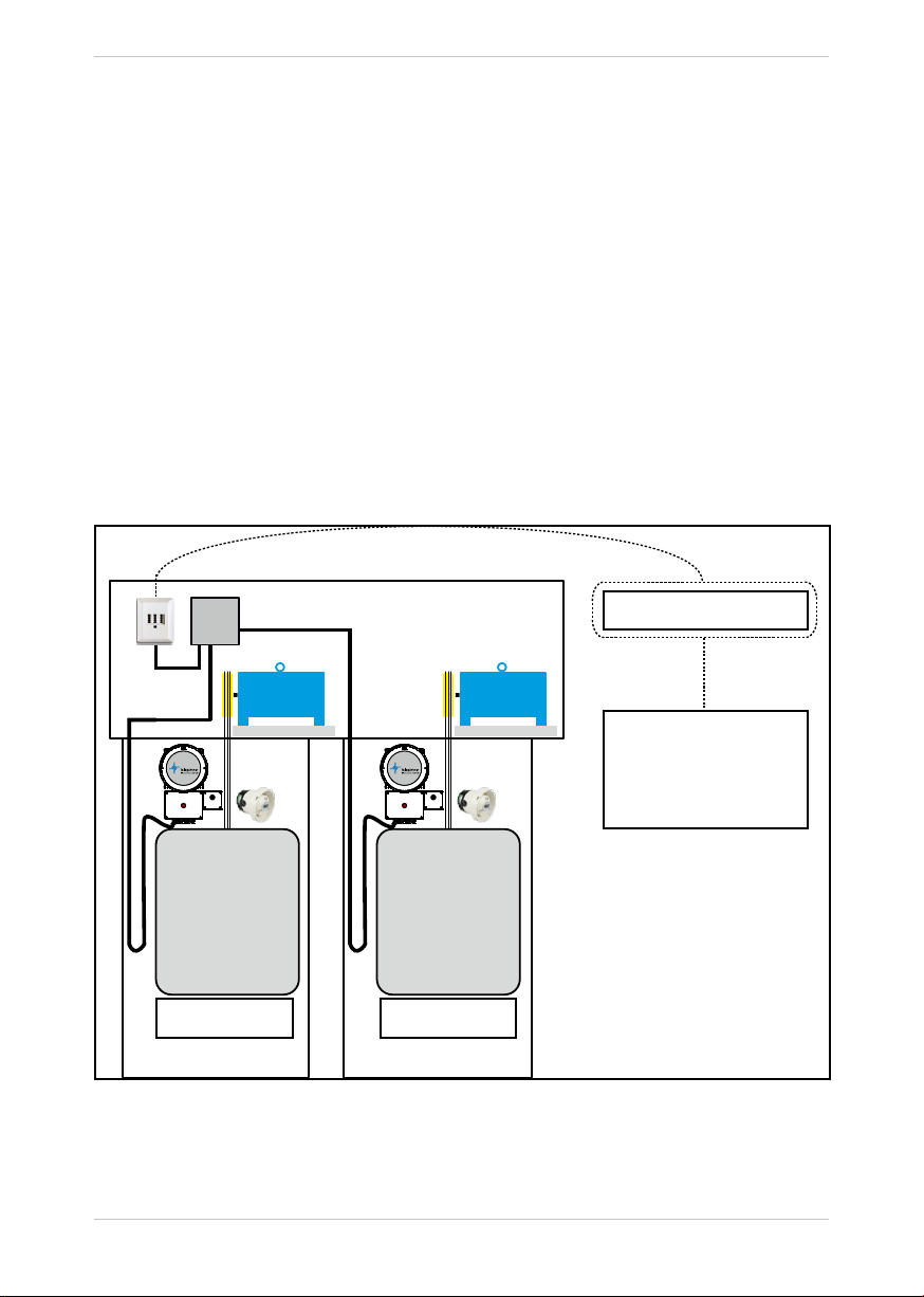
Example: Two NRT 1 EX G3 on a single phone line using a NR-Line 230.
NR-Line 230
NRT 1 EX G3 at
port 21
Telephone / mobile
Network
NRT 1 EX G3 at
port 22
Call takes place on:
Emergency call centres/
Doorman/
Caretaker

5
Set-up and function
1.2 Description of connections and control elements
1.2.1 Overview
1. Integrated emergency call button.
2. EX-protected microphone. Is activated when an emergency call is triggered by the integrat-
ed emergency button.
3. EX-housing for circuit board. Must not be opened!
4. Fixing holes
5. Glands for cables. Unused cable glands must be closed with suitable plugs.
6. Screws for terminal box.
6
5
4
3
2
1
4

6
Set-up and function
1.2.2 Dimensions / housing drawings
227
ø289
236
210
236
210ø11
176,5
~446
227

7
Set-up and function
1.2.3 Terminal designations
Terminal block XD1:
No. Description No. Description
1 Power supply +24 V DC 11 Reserved
2 Power supply GND 12 Reserved
3 Configurable input 13 Input for emergency call button 1
4 Configurable input 14 Input for emergency call button 1
5 Output pictogram display
„Please wait“, +
15 Input for emergency call button 2
6 Output pictogram display
„Please wait“, -
16 Input for emergency call button 2
7 Output pictogram display
„Please speak“, +
19 Output EX - speaker, +
8 Output pictogram display
„Please speak“, -
20 Output EX - speaker, -
9 Input „End of alarm“ 21 Phone line, A
10 Input „End of alarm“ 22 Phone line, B
PE PE PE PE
XD1 XD2
NO
SF1
1234 5 6 7 8 9 10 PE
11 12 15 16 17 18 19 20 21 22 PE
123
456
PA PA
PA PA

8
Set-up and function
Terminal block XD 2:
No. Description No. Description
1 Microphone 1, + (white wire) 4 Microphone 2, - (brown wire)
2 Microphone 1, - (brown wire) 5 Microphone 3, + (already connected)
3 Microphone 2, + (white wire) 6 Microphone 3, - (already connected)
PA Connection „Shield microphone cable“ PA Connection „Shield microphone cable“
PA Connection „Shield microphone cable“ PA Connection „Shield microphone cable“
2. Mounting
2.1 Prerequisites
To operate the NRT, at least one analogue telephone connection in one of the following versions
is required:
• Analogue telephone main connection
• Analogue extension of a telephone system
• Telegärtner GSM gateway
The transfer point (TAE socket) should be in the machine room or near the clamping point of the
suspension cable.
The telephone connection must be reserved exclusively for the NRT, i.e. no other dialling devices
(such as modems or fax machines) may be connected to the same connection.
Two free wires in the suspension cable are required for the telephone line. In order to avoid inter-
ference, twisted pair and shielded cables must be used.
An uninterruptible power supply of 24V DC must be provided for NRT. Alternatively, an uninter-
ruptible power supply is available from Telegärtner as an additional device (Art. No. 601364).
2.2 Mounting location
The emergency call device is intended for mounting on the roof of the lift car.
The loudspeaker is to be placed in such a way that sufficient acoustic sound coverage of the car
and the lift shaft is ensured.
2.3 Telephone line
Route the telephone cable from the machine room to the NRT via the suspension cable and con-
nect it to clamp 21 and 22 on terminal block XD1. The polarity does not need to be observed.
We expressly point out that interference on the voice connection may occur if
no separate suspension cable or shielded wire pair is used in the suspension
cable.
!

9
Mounting
XD1 XD2
NO
SF1
1234 5 6 7 8 9 10 PE
11 12 13 14 15 16 19 20 21 22 PE
123
456
PA PA
PA PA
2.4 Loudspeaker / Microphone
Depending on the model, the loudspeaker is mounted either on the cabin roof or as a ceiling
loudspeaker for the cabin. The loudspeaker is to be placed in such a way that sufficient sound
coverage of the car and the elevator shaft is ensured.
XD1 XD2
NO
SF1
1234 5 6 7 8 9 10 PE
11 12 13 14 15 16 19 20 21 22 PE
123
4 5 6
PA PA
PA PA
1. EX-Loudspeaker for mounting upon the cabin roof. The loudspeaker is connected to
clamps 19 and 20 of terminal block XD1.
2. Microphone in Ex-version for mounting in the cabin. The microphone is connected to
clamps 1 and 2 of terminal block XD2.
Terminal 1 = microphone + (white wire), terminal 2 = microphone - (brown wire).
The shield of the microphone cable is connected to a free clamp “PA”.
Engine room NRT
Suspension cable
2
1
3

10
Mounting
3. Microphone in Ex-version for mounting in the cabin. The microphone is connected to
clamps 3 and 4 of terminal block XD2.
Terminal 3 = microphone + (white wire), terminal 4 = microphone - (brown wire).
The shield of the microphone cable is connected to a free clamp “PA”.
Connect only one device at a single input for the microphones or output for the
loudspeaker.
The microphone used must be “Microphone NRT 1 EX G3”, Art. No. 601361!
2.5 Emergency call buttons
Up to two potential-free emergency call buttons can be connected directly to the NRT.
An emergency button is already integrated in the device and is used to trigger an emergency
call from the roof of the elevator car.
The connected emergency buttons must switch the input potential-free!
The following table shows which emergency button activates which microphone:
Button Microphone Usage
1 1 Car
2 2 Under the car
3 (integrated) 3 (integrated) Top of the car
XD1
1234 5 6 7 8 9 10 PE
11 12 13 14 15 16 19 20 21 22 PE
XD1
1234 5 6 7 8 9 10 PE
11 12 13 14 15 16 19 20 21 22 PE
1. Emergency call button (Clamp 13 & 14) at COP, normally open (NO)
2. Emergency call button (Clamp 15 & 16) under the car, normally open (NO)
1.
1. Emergency call button (Clamp 13 & 14) at COP, normally closed (NC)
1. Emergency call button (Clamp 15 & 16) at under the car, normally closed (NC)
Unused emergency call buttons must always be configured as normally open.
From the emergency call buttons, either the normally closed (NC) contacts or the
normally open (NO) contacts can be used.
The type of contact (normally closed or normally open) can be configured. The
normally open (NO) contact type is pre-set ex works.
!
1 2 1 2
A B
A
B
!

11
Mounting
2.6 Pictograms
Illuminated fields with pictograms according to EN 81-28:2018 can be connected to terminal
block XD1.
The terminal designations are:
Clamp 5 + for pictogram „Please wait“
Clamp 6 - for pictogram „Please wait“
Clamp 7 + für Piktogramm „Please speak“
Clamp 8 - für Piktogramm „Please speak“
XD1
1234 5 6 7 8 9 10 PE
11 12 15 16 17 18 19 20 21 22 PE
+
-

12
Mounting
2.7 Configurable input
To adapt the behaviour to certain situations, the NRT has a configurable input at clamps 3 & 4 on
terminal block XD1.
The input can be used in the following operating modes:
1. Off
Input is deactivated.
2. Filter
When the contact is bridged, the emergency call is filtered (misuse suppression) in
accordance with EN 81-28:2018.
Emergency call test (LMS)
If the input is configured as LMS and is bridged, pressing an emergency call button does
not initiate an emergency call, but only an emergency call test as follows:
1. The panel displays (pictograms) both light up (function has to be checked by LMS).
2. The audio test is carried out for all microphone / loudspeaker combinations for which
this has been activated.
3. The panel displays (pictograms) are switched off.
Connection example:
XD1
1234 5 6 7 8 9 10 PE
11 12 15 16 17 18 19 20 21 22 PE

13
Mounting
2.8 Supply voltage
The NRT requires an uninterruptible supply voltage of 24VDC, which is connected to the termi-
nal block XD1, clamp 1 + 2. Please pay attention to correct polarity (1= + / 2= -)!
XD1
1234 5 6 7 8 9 10 PE
11 12 15 16 17 18 19 20 21 22 PE
+
-
24 V DC,
Battery-backup
required!
Important note:
The supply voltage may only be connected during commissioning.
!
14
Mounting
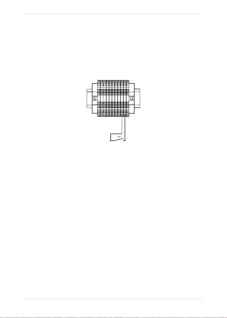
2.9 Button “End of alarm”
A button for initiating the end of alarm can be connected to clamps 9 & 10 of the XD1 terminal
block.
After a successful rescue of persons, the button can be pressed by the rescue staff.
The end of alarm message is automatically sent to the emergency call centre and the active
emergency call is deleted.
Alternatively, the end of the emergency call can also be triggered by the NRZ alarm receiver.
XD1
1234 5 6 7 8 9 10 PE
11 12 13 14 15 16 19 20 21 22 PE
3. Commissioning
The commissioning can be carried out after establishing all the necessary electrical connections.
3.1 Connecting the supply voltage
The installation is complete when the operating voltage is connected with the correct polarity.
The NRT carries out a short self-test.
3.2 Checking the installation
Emergency call buttons
It is essential to check the correct function of all connected emergency call buttons. If a button
is pressed for > 3seconds, a dial tone can be heard from the loudspeaker. In addition, a tone
sequence (20xbeep) sounds in unprogrammed devices.
If the “INPUT” terminal is wired and configured as an emergency call filter, it must be temporarily
removed. Otherwise the triggering is suppressed via the emergency call button.
Alternatively, the filter can also be bypassed. To do this, the emergency call button must be
pressed for a configurable time.
The time is set to 30seconds ex works and can be changed. Please take a look at page Seite
27.
Important note:
The emergency call buttons must remain functional even if the main lift power supply fails.

15
Commissioning
Voice connection
In order to check the quality of the voice connection, a connection to the emergency call device
must be established by means of a telephone call (or a machine room telephone):
1. Call the telephone number of the connection from a mobile phone, extension or other tele-
phone. For single device operation, please continue with point 3.
2. If an emergency call device responds with the post-dial request, dial the suffix digit (21-26)
for the required emergency call device.
3. The emergency call device answers with a beep. By entering the security code 0000 and
then #*06, a voice connection (4-tone sequence) is established.
There are various setting options that can be used to adjust the device by entering the following
keys on the telephone:
Key Function
1 Switch to external call station SM#1
2 Reduce the microphone sensitivity
3 Increase the microphone sensitivity
4 Switch to external call station SM#2
5 Reduce the loudspeaker gain
6 Increase the loudspeaker gain
7 Switch to internal call station 3
8 Accept the active connection
9 Disconnect the connection
0 Delete the emergency call and hang up
Each button press is confirmed by 1x beep from the emergency call device. If the microphone
sensitivity or loudspeaker gain is at the maximum or minimum value, this is acknowledged with
two beeps.
Important information:
• Configure the line impedance of the NRT to the corresponding value (fixed network or
GSM).
• Check the voice connection to each connected call station
(change with keys 1, 4 and 7).
• Depending on the installation location, the distance between microphone and loud-
speaker, etc., acoustic feedback may occur. Please be very careful, therefore, when
changing the parameters. Under certain circumstances, it may not be possible to
recognise tone dialling signals during acoustic feedback. In this case, please remove
the microphone and reduce the microphone sensitivity or loudspeaker gain.
3.3 Carrying out the configuration
If all previous items have been completed successfully, the NRT must be configured.
Please refer to chapter 4 of this manual.
When connected to a Telegärtner NRZ alarm receiver, it can carry out all configuration tasks.

16
Commissioning
3.4 Carrying out the emergency call test
After all changes to the installation or configuration are complete, a final emergency call test
must be performed.
Important note: If emergency call filtering is activated, this must be taken into account.
The following points at least must be checked during an emergency call test:
- The emergency call must be received quickly at the desired emergency call centre,
i.e. without redialling if possible.
- The emergency call personnel must be able to clearly assign the lift.
- The voice connection must be interference-free and comprehensible in both
directions.
- In addition, further points can be checked where applicable:
- Callback to the lift car should be possible
- Emergency call filtering with open door
- The function of the pictogram displays “Please wait” and “Please speak”
and the correct assignment
!

17
Configuration
4. Configuration of the NRT 1 EX G3
4.1 General information
The NRT can be programmed in two different ways:
1. Configuration via a touch-tone telephone
2. Configuration via the control centre
Before the configuration of the emergency call device, make sure that all steps described in the
Assembly chapter have been carried out.
4.2 Function
Connection
The NRT 1 EX G3 can be connected to control centres that support the Telegärtner (NRZ) or
P100 data protocol.
It is also possible to connect to touch-tone telephones (porter, janitor, etc.). For each of the four
possible call numbers that the emergency call device can call in the event of an emergency
call, the destination of the connection is freely selectable; i.e. emergency phone number 1 could
be connected to a telephone at a gate, emergency phone number 2 to the mobile phone of a
caretaker, emergency phone number 3 to a control centre with Telegärtner data protocol and
emergency phone number 4 to a control centre with P100 data protocol.
There are six different options (identifiers) for connection to telephones:
Identifier Description
Telephone Emergency call destination is a telephone. Acknowledgement is
not required. The voice connection is established immediately after
dialling the telephone number. Redials are only performed by the NRT
if the destination is busy.
Attention: This identifier must not be used if the call can also be ans-
wered by an answering machine or a mobile box.
Telephone +
acknowledgement
The emergency call destination is a touch-tone telephone. Ack-
nowledgement by pressing a number key on the called telephone is
mandatory for establishing a voice connection. Redials are carried out
by the NRT until they are acknowledged.
Telephone + optional
acknowledgement
The emergency call destination is a touch-tone telephone. Acknowled-
gement by pressing a number key on the called telephone is possible,
but not necessary. The emergency call device also automatically
detects if the called telephone is off-hook and if a voice connection is
available. The voice connection is automatically established.
Attention: This identifier must not be used if the call can also be
answered by an answering machine or a mobile box.

18
Configuration
Telephone + voice
announcement
The emergency call destination is a touch-tone telephone. The called
telephone first receives a voice announcement to inform the called
party of the reason for the call, the location of the lift and to carry out
the acknowledgement. This voice announcement is freely definable
and can be recorded via a telephone command (see pageSeite 32).
The announcement is played cyclically until an acknowledgement is
made via a number button on the telephone or the device dials the
next emergency number.
P100 alarm receiver The emergency call destination is a control centre that can process
the P100 protocol. When the emergency call centre has been reached,
the emergency call device exchanges a short data protocol so that
the emergency call can be identified and assigned. In case of errors,
which cannot be corrected during transmission of data, the dialling
attempts are continued.
NRZ alarm receiver The emergency call destination is a control centre that can process
the NRZ protocol from Telegärtner. When the connetion between NRT
and NRZ is established, the emergency call device exchanges a short
data protocol so that the emergency call can be identified and
assigned. In case of errors, which cannot be corrected during trans-
mission of data, the dialling attempts are continued.
Emergency call filtering
Emergency call filtering is used to filter out fake emergency calls or to delay the emergency call.
If this function has been programmed accordingly and the “INPUT” input on the emergency
call device has been wired accordingly, the emergency call for the respective call station is not
triggered.
Emergency call filtering is not activated while a stored emergency call is present. See also
“Emergency call end/Acknowledge emergency call”.
The filter can be bypassed for test purposes (Filter bypass). To do this, the emergency call but-
ton must be pressed for a configurable time. The time is pre-set to 30seconds ex works.
Dialling
If the emergency call has been accepted as a “real” emergency call (see Emergency call filter-
ing), the pictogram display for “Please wait” is activated at the “PICTO” output. The emergency
device then dials the first programmed emergency number. The dialling and the audible tones of
the telephone line can be heard from the loudspeaker for checking purposes.
If an additional acoustic signal is required when an emergency button is pressed, the emergency
horn can be activated. When the emergency horn is activated, the loudspeaker plays a signal
tone until the first emergency number is dialled.
If the reception centre does not answer immediately (busy, wrong number, ...), the NRT hangs
up and dials the next programmed number after approx. ten seconds. The number of dialling
attempts can be set (ex works 12 dialling attempts are preconfigured).
The yellow “Please wait” display is active during the entire connection set-up.
Reassuring text
To reassure the trapped person, a self-recorded voice announcement can be played into the lift
car after the emergency call button has been pressed. This announcement is played before each
dial attempt. Recording, checking and activating announcements is only possible via configura-
tion using a touch-tone telephone (see “#* 73 – Reassuring text” on page Seite 31).

19
Configuration
Announcement text for identification (only when connected to a telephone)
If the emergency call device is connected to a telephone (caretaker, 24-h manned gate,...), a
voice announcement can be recorded on the emergency call device, which the emergency call
device plays back to the emergency call recipient before the actual voice connection with the
person trapped to identify the location, etc.
If the emergency call is acknowledged from the telephone, the emergency call device automati-
cally activates the voice connection to the lift car.
Recording, checking and activating announcements is only possible via configuration using a
touch-tone telephone (see „#*77 - Record “Identification” announcement“ auf Seite 32).
Voice connection
If the emergency call has been successfully made, the voice connection to the lift car is activat-
ed. The call station that triggered the emergency call is automatically activated.
The pictogram display for “Please speak” is activated at the “PICTO” output to indicate that the
call station is ready to speak. At the same time, a 4-tone sequence sounds on the loudspeaker
for acoustic signalling.
Ending the voice connection
The emergency call device automatically recognises when the voice connection of the called
telephone/control centre has been disconnected by a busy tone from the telephone network.
Otherwise, the voice connection is automatically disconnected after the programmed communi-
cation time has elapsed. It is also possible to hang up the phone if the called party presses the
“9” key on the telephone.
Emergency call end/Acknowledge emergency call
The device offers two different operating modes for the emergency call end.
Automatic emergency call end:
An emergency call is automatically terminated after a voice connection. This operating mode is
pre-set ex works.
Manually according to EN81-28:2018:
An emergency call remains stored until the emergency call device has been informed of the
emergency call end.
There are several ways to initiate the emergency call end:
1. After the rescue and functional check of the lift, the rescue service presses the emergency
call button and informs the emergency call centre about the successful freeing. The call is
then ended by the emergency call centre by pressing the 0 key on the telephone.
2. The rescue service presses the “End of alarm” button connected to the NRT.
The NRT then reports the emergency call end to the emergency call centre.
3. The emergency call centre triggers the emergency call end via the reception software.
Important note:
As long as an emergency call is stored, the yellow pictogram display in the lift car lights,
the emergency call filtering is disabled and the emergency call device can be called at any
time despite activated call protection. This operating mode complies with the upcoming
standard DIN EN 81-28:2018 and can be activated if required.

20
Configuration
Calling
The control centre or the rescuer may call the emergency call device to inform the trapped
person about the status of the rescue. The number of the emergency call device is dialled and a
voice connection to the call station at which an emergency call was last triggered is automatically
established.
If call protection has been activated, a stored emergency call must be present for the device to
establish the voice connection or the corresponding call protection code must be entered on the
device.
When the device is called, the following direct commands can be entered on the telephone
keypad:
Key Function
4 Automatic change of voice direction (default setting)
7 Listening
* Speaking
Messages
If the emergency call device is connected to a control centre with Telegärtner or
P100 data protocol, the NRT can send fault or clear messages for the following events:
Audio test faulty :
The automatic audio test was not successful, i.e. the loudspeaker or microphone does not work.
Emergency button test faulty:
Passive test:
The passive test of the emergency call button constantly checks if it is activated all the
time or if the supply line is interrupted when a normally closed contact is used.
A corresponding message is transmitted if one of the two cases occurs.
The audio test is linked by the test intervals to the time of the routine call, i.e. these tests are
carried out after the routine call and the corresponding messages are sent.
Timer function
The NRT has a routine call for function and line monitoring. Routine calls can be programmed
daily, weekly, monthly or, for example, at a fixed time at 3-day intervals. The destination number
of the routine call can be either a control centre with NRZ or P100 data protocol. Activation of the
routine call on a telephone is also possible. A recorded Morse tone sequence
distinguishes the routine call from a normal emergency call.
Important note:
With the upcoming EN81-28:2018 standard, it is necessary that an unsuccessful routine
call is signalled by alternating flashing pictogram displays in the lift car. This mode can
be activated in the emergency call device. For details, see pageSeite 28.
T E S T
Table of contents
Popular Industrial Equipment manuals by other brands


CKD
CKD INDEXMAN PPLX Series instruction manual

ITOH DENKI
ITOH DENKI F-RAT-NX75 operating instructions

Chamberlain
Chamberlain Clopay HPH1 installation manual

Blastrac
Blastrac BDC-655 EX Original instructions

GESTRA
GESTRA VKP 40Ex Installation & operating instructions

Aerotech
Aerotech ANT95XY Series Hardware manual