Atmel EVK2160A User manual

10623A–AT42–06/09
USB Plug-in Card for the EVK2160A
Demonstration Kit
....................................................................................................................
User Guide

ii USB Plug-in Card User Guide
10623A–AT42–06/09

USB Plug-in Card User Guide 1-1
10623A–AT42–06/09
Section 1
Overview and Procedure
1.1 Introduction
This application note details how to set up the EVK2160A standalone evaluation board to connect to a
PC using the USB plug-in card, in order to run EVK2160A demonstration software.
New users are recommended to work through the Quickstart guide to familiarise themselves with the kit
and software before reading this User Guide.
For detailed information regarding these products, including the latest datasheet and demonstration
software, go to www.atmel.com.
Note: This User Guide should be read in conjunction with Software GUI for the EVK2160A
Demonstration Kit User Guide.
1.2 Getting Started
1.2.1 Components Required
The following components are required:
1 x EVK2160A Evaluation Board
1 x USB Plug-in Card 9206
1 x Soldering Iron
1xSolder
1xTweezers
Wire to fit
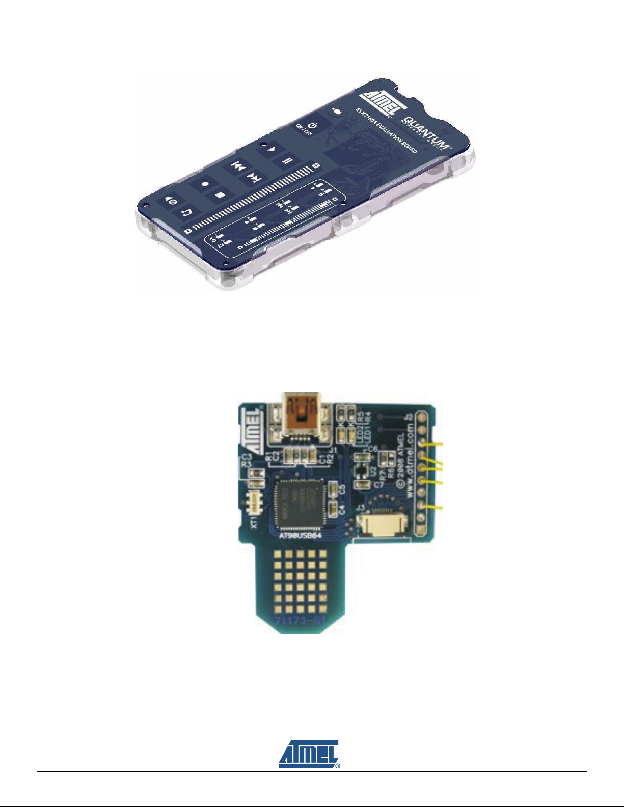
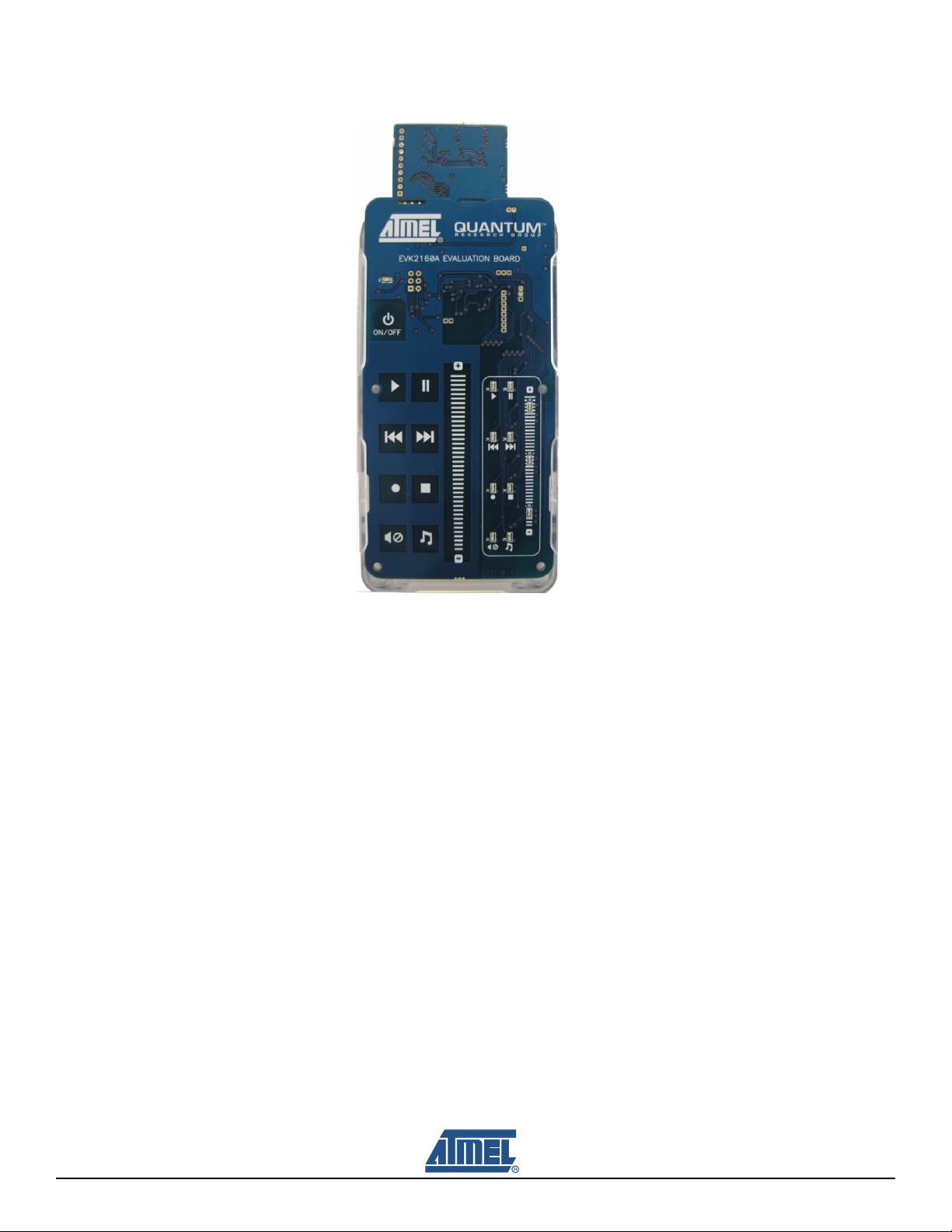
1.2.2 EVK2160A Evaluation Board
The EVK2160A Evaluation Board comprises one AT42QT2160-MMU (QT2160 ) with 16 channels; these
are configured as 8 capacitive sensing keys and one slider, made of a further 8 capacitive sensing keys
(see Figure 1-1 on page 1-2).

Overview and Procedure
1-2 USB Plug-in Card User Guide
10623A–AT42–06/09
Figure 1-1. EVK2160A Evaluation Board
1.2.3 USB Plug-in Card
The USB plug-in card enables standalone evaluation boards such as the EVK2160A to connect to PC
applications through a USB port, using I2C-compatible communications (see Figure 1-2).
Figure 1-2. USB Plug-in Card
3
5
6
7
8

Overview and Procedure
USB Plug-in Card User Guide 1-3
10623A–AT42–06/09
1.3 EVK2160A Preparation
The USB plug-in card is used to supply external power to the unit. To protect the unit from possible
damage through cross-powering of external and battery power:
1. Slide out the EVK2160A PCB from the moulded case (see Figure 1-3).
2. Remove the battery from the EVK2160A evaluation board (if fitted).
3. Remove diode D13.
4. Remove the 0resistor from D12 and fit to D13.
Figure 1-3. EVK2160A Adaptations
1.4 USB Plug-in Card Setup
To communicate and provide power, see Table 1-1 for the wires to attach between the USB plug-in card
and the EVK2160A:
Note: * Pin one on J2 is denoted by a square pin (see Figure 1-4 on page 1-4).
Table 1-1. Connections Between EVK2160A and the USB Plug-in Card
USB Plug-in Card Connector J2 Pin* EVK2160A
3 CHG
5SDA
6SDL
7 D13/TP17
8 - ve Pin or GND pad

Overview and Procedure
1-4 USB Plug-in Card User Guide
10623A–AT42–06/09
Figure 1-4. USB Plug-in Card and EVK2160A Connections
1.5 EVK2160A and USB Plug-in Card Assembly
To assemble the EVK2160A and USB Plug-in Card:
1. Slide the USB plug-in card into the battery slot on the EVK2160A PCB (see Figure 1-5).
Figure 1-5. USB Plug-in Card and EVK2160A Connections
2. Slide the EVK2160A assembly into the moulded case (see Figure 1-6 on page 1-5). The assembly
setup for connection to PC software is now complete.
3. Refer to the Software GUI for the EVK2160A User Guide for details of the software GUI interface.

Overview and Procedure
USB Plug-in Card User Guide 1-5
10623A–AT42–06/09
Figure 1-6. USB Plug-in Card and EVK2160A Setup Complete

Overview and Procedure
1-6 USB Plug-in Card User Guide
10623A–AT42–06/09
Figure 1-7. EVK2160A Demonstration Board Schematic (sheet 1 of 71078-1)

Overview and Procedure
USB Plug-in Card User Guide 1-7
10623A–AT42–06/09
Figure 1-8. EVK2160A Demonstration Board Schematic (sheet 2 of 71078-1)

Overview and Procedure
1-8 USB Plug-in Card User Guide
10623A–AT42–06/09
Figure 1-9. USB Plug-in Card Schematic

USB Plug-in Card Design Guide
10623A–AT42–06/09
Associated Documents
User Guide – Software GUI for the EVK2160A Demonstration Kit
Revision History
Revision No. History
Revision AX – June 2009 Initial version for EVK2160A (71078-1) and
USB Plug-in Card (71173-B1)

10623A–AT42–06/09
Headquarters International
Atmel Corporation
2325 Orchard Parkway
San Jose, CA 95131
USA
Tel: 1(408) 441-0311
Fax: 1(408) 487-2600
Atmel Asia
Unit 01-05 & 16, 19/F
BEA Tower, Millennium City 5
418 Kwun Tong Road
Kwun Tong
Kowloon
Hong Kong
Tel: (852) 2245-6100
Fax: (852) 2722-1369
Atmel Europe
Le Krebs
8, Rue Jean-Pierre Timbaud
BP 309
78054 Saint-Quentin-en-
Yvelines Cedex
France
Tel: (33) 1-30-60-70-00
Fax: (33) 1-30-60-71-11
Atmel Japan
9F, Tonetsu Shinkawa Bldg.
1-24-8 Shinkawa
Chuo-ku, Tokyo 104-0033
Japan
Tel: (81) 3-3523-3551
Fax: (81) 3-3523-7581
Touch Technology Division
1 Mitchell Point
Ensign Way
Hamble
Southampton
Hampshire SO31 4RF
United Kingdom
Tel: (44) 23-8056-5600
Fax: (44) 23-8045-3939
Product Contact
Web Site
www.atmel.com
Technical Support
Sales Contact
www.atmel.com/contacts
Literature Requests
www.atmel.com/literature
Disclaimer: The information in this document is provided in connection with Atmel products. No license, express or implied, by estoppel or otherwise, to any
intellectual property right is granted by this document or in connection with the sale of Atmel products. EXCEPT AS SET FORTH IN ATMEL’S TERMS AND CONDI-
TIONS OF SALE LOCATED ON ATMEL’S WEB SITE, ATMEL ASSUMES NO LIABILITY WHATSOEVER AND DISCLAIMS ANY EXPRESS, IMPLIED OR STATUTORY
WARRANTY RELATING TO ITS PRODUCTS INCLUDING, BUT NOT LIMITED TO, THE IMPLIED WARRANTY OF MERCHANTABILITY, FITNESS FOR A PARTICULAR
PURPOSE, OR NON-INFRINGEMENT. IN NO EVENT SHALL ATMEL BE LIABLE FOR ANY DIRECT, INDIRECT, CONSEQUENTIAL, PUNITIVE, SPECIAL OR INCIDEN-
TAL DAMAGES (INCLUDING, WITHOUT LIMITATION, DAMAGES FOR LOSS OF PROFITS, BUSINESS INTERRUPTION, OR LOSS OF INFORMATION) ARISING OUT OF
THE USE OR INABILITY TO USE THIS DOCUMENT, EVEN IF ATMEL HAS BEEN ADVISED OF THE POSSIBILITY OF SUCH DAMAGES. Atmel makes no
representations or warranties with respect to the accuracy or completeness of the contents of this document and reserves the right to make changes to specifications
and product descriptions at any time without notice. Atmel does not make any commitment to update the information contained herein. Unless specifically provided
otherwise, Atmel products are not suitable for, and shall not be used in, automotive applications. Atmel’s products are not intended, authorized, or warranted for use
as components in applications intended to support or sustain life.
© 2009 Atmel Corporation. All rights reserved. Atmel®, Atmel logo and combinations thereof, and others are registered trademarks. Other terms
and product names may be registered trademarks or trademarks of others.
Table of contents