Atmos Varioair 3 User manual

Varioair 3
GA1GB.140303.0
2022-10 Index 20
0124
Operating Instructions
English

1.0 Introduction.........................................................3
1.1 Notes on operating instructions ............................3
1.2 Intended use .........................................................4
1.3 Function ................................................................4
1.4 Explanation of symbols.........................................4
2.0 For your safety....................................................5
3.0 Setting up and starting up .................................6
3.1 Scope of supply ....................................................6
3.2 Illustrations............................................................6
3.3 Connections..........................................................8
3.3.1 Electrical connection.............................................8
3.3.2 Connecting a nystagmograph...............................8
3.3.3 Equipotential bonding conductor connection ........8
3.3.4 Connecting the handle..........................................8
3.3.5 Air inlet..................................................................8
3.4 Starting up.............................................................8
4.0 Operation.............................................................9
4.1 Adjusting temperatures.........................................9
4.2 Selecting temperature levels.................................9
4.3 Adjusting stimulation time .....................................9
4.4 Description of operating modes ............................9
4.4.1 Preparation mode .................................................9
4.4.2 Stimulation mode ................................................10
4.4.3 Standby mode.....................................................10
5.0 Cleaning and care.............................................11
5.1 General information on cleaning and disinfection11
5.2 Recommended instrument disinfectants.............11
5.3 Recommended surface disinfectants..................11
6.0 Maintenance and service .................................12
6.1 Sending in the device..........................................12
7.0 Troubleshooting................................................13
8.0 Accessories and spare parts...........................14
8.1 Accessories.........................................................14
8.2 Spare parts .........................................................14
9.0 Technical data ...................................................15
10.0 Disposal.............................................................16
11.0 Notes on EMC....................................................17
2
Table of contents

1.1 Notes on operating instructions
These operating instructions contain important notes on how
to operate the Varioair 3 correctly and eectively. Therefore,
they are intended not only for new operating personnel to be
instructed in its use, but also for use as a reference manu-
al. They help to avoid risks and also to reduce repair costs
and down-times. Furthermore, reliability and service-life of
the equipment will be increased. For these reasons, these
operating instructions must always be kept available
near the device.
Prior to rst use, please peruse the chapter “For your safety”
in order to be prepared for any possible dangerous situa-
tions. To do this during work would be too late.
The basic principles are:
Judicious and careful work provides best protection
against accidents!
Operational safety and readiness for use of the device de-
pend not only on your capabilities, but also on the care and
maintenance given to the Varioair 3. For this reason, regular
cleaning and service work are a must. Major maintenance
and repair work may be carried out only by expert personnel
authorized by ATMOS. In case of repairs, you should insist
that only original spare parts are used. You will then have
the warranty that operational safety, readiness for work, and
the value of your device will be preserved.
• The product Varioair 3 bears CE marking CE 0124 in
accordance with EU Directive 93/42/EEC concerning
medical devices and meets the basic requirements of
Annex I to this directive.
• The product Varioair 3 complies with all applicable
requirements of the Directive 2011/65/EU restricting the
use of certain hazardous substances in electrical and
electronic equipment (“RoHS”).
• The declarations of conformity and our general standard
terms and conditions can be obtained on our website at
www.atmosmed.com.
• The quality management system applied at ATMOS has
been certied according to international standard EN ISO
13485.
• Reprints—also in extracts—only with permission in writ-
ten form by ATMOS.
Abbreviations/symbols contained in these operating
instructions:
• Indicates a list
- Subdivision of a list/activity
The recommended sequence must be followed in each case!
)Indicates particularly important advice!
ªDescribes the eect of an activity
ATMOS
MedizinTechnik GmbH & Co. KG
Ludwig-Kegel-Str. 16
79853 Lenzkirch
Germany
Phone: + 49 7653 689-0
Fax:
+ 49 7653 689-190
+ 49 7653 689-393 (Service Center)
E-mail: [email protected]
Internet: www.atmosmed.com
3
1.0 Introduction
1.2 Intended purpose
Product name: Varioair
Main functions: Stimulation of the vestibular organ
Intended purpose: Stimulation of the vestibular organ
Intended users /
User prole:
Doctors and medical specialists
Intended patient
target group:
Patients of all ages without restric-
tions
Medical conditions
to be diagnosed,
treated or moni-
tored:
Vertigo due to a disorder of the
vestibular organ
Application organ: External auditory canal to eardrum
Application period:
Transient (< 60 min)
Application envi-
ronment:
Outpatient medical facilities, e.g.,
ENT practices, hospital outpatient
departments, medical care centers
Patient selection
criteria:
Patients with intact, physiological
eardrum and external auditory
canal
Indications: Dierential diagnostics for vertigo
Medical contra-
indications:
Pathological eardrum
Other contra-
indications:
Pathological external auditory canal
Warnings: N/A
The product is: active
Sterility/specic
microbial status:
Non-sterile
Single use product
/ reprocessing:
Not a single-use product. Repro-
cessing according to instructions
for use.
1.3 Function
• After activating the main switch, the optical indicators are
tested.
• The device then enters the standby mode in which the
heating and the pump are switched o.
• Possibility to switch to the stimulation mode for stimulat-
ing the vestibular organ. The Varioair 3 is equipped with a
timer for preselecting the stimulation duration.
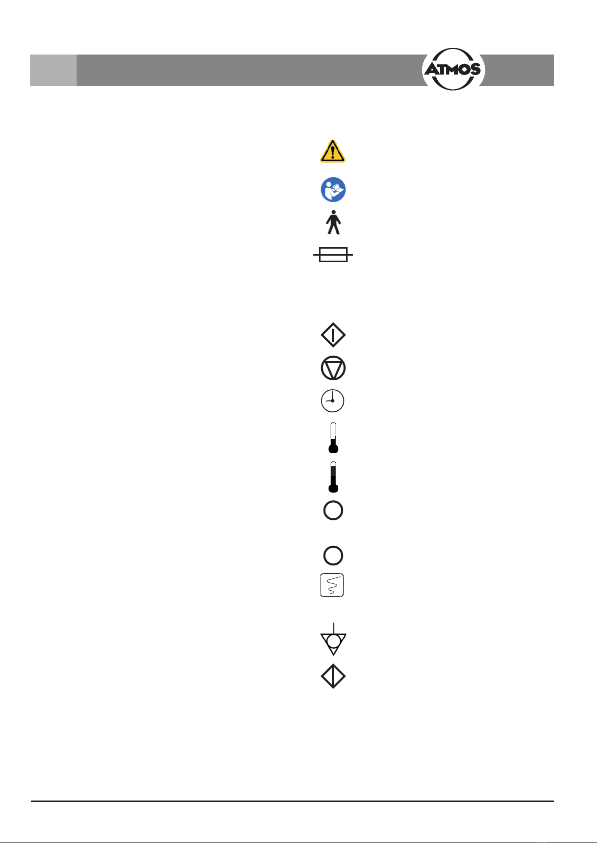
1.4 Explanation of symbols
Observe operating instructions!
According to ISO 7000/0434,
DIN 30600/1008, IEC 348
Follow operating instructions (blue)
Type B equipment as per IEC 417
Fuse
according to IEC 417/5016, DIN 30600/0186
°C Temperature in degree centigrade
sTimer adjustment in seconds
Start
Stop
Timer
Cold stimulation level
Warm stimulation level
•Heating and air ow ON
•Heating and air ow OFF (standby)
Control output for connecting a nystagmo-
graph
(graphical recorder as per DIN 30600,
IEC 417 5192)
Equipotential connection
DIN 30600 495, ISO 417 5021
Air lter
DIN 24300
4
1.0 Introduction

• The Varioair 3 is produced according to IEC 601 / EN
60601 and listed in the following classes:
- VDE Class of protection 1
- Class IIa (93/42/EEC).
• The device may only be connected to a properly installed
grounded safety socket.
• The Varioair 3 may only be used under the supervision
of skilled sta who have been authorized by ATMOS and
trained in its operation (IEC 601-1 / EN 60601-1).
• The mains voltage indicated on the type plate must corre-
spond to the values of the supply network.
• Make sure prior to every application of the equipment that
it is technically safe and in proper condition. Damaged
cables must be replaced immediately!
• Correct conguration in assembly of country-specic
connections:
- green/yellow: protective conductor (PE)
- blue: neutral conductor (N)
- black or brown: phase (L)
• The control panel must be clearly visible and accessible
for the user. Ensure sucient stability of the installation
surface.
• Prior to application, the air temperature must be checked
by the user (display)!
• Switch o the main switch after nishing work in the
practice.
• The Varioair 3 may only be operated in rooms used for
medical purposes, but not in areas subject to explosion
hazards and not in oxygen-rich environments.
• All additional equipment that is connected to the analog
and digital interfaces of the device must meet the require-
ments of relevant EN specications (e.g., EN 60950 for
data processing equipment and EN 60601 for electrical
medical equipment). In addition, congurations must
satisfy system specication EN 60601-1-1. When addi-
tional equipment is connected to the signal input or signal
output section on the device, the person carrying out the
connection is deemed a “system conguration operator”
and as such is responsible for meeting the requirements
of system specication EN 60601-1-1. If you have any
questions, please contact your local specialist supplier or
ATMOS Technical Service.
• ATMOS is not liable for personal injury and damage to
property if
- no original ATMOS parts are being used,
- the advice for use in these operating instructions is
not being observed,
- assembly, new settings, alterations, extensions, and
repairs have been carried out by personnel not au-
thorized by ATMOS.
• The validity for the certicate of conformity expires if the
customer or a third party manipulates the unit, e.g., by
making modications of any kind, using non-authorized
accessories, removing warning or information labels as
well as using the unit for inappropriate applications.
• Please note:
A medical isolation transformer with earth leakage
monitor or any similar safety system acc. to EN 60601-
1 is required if several devices are connected over one
common power supply. The transformer must correspond
to the power consumption of all the devices to be con-
nected.
5
2.0 For your safety
3.1 Scope of supply
• Varioair 3 basic unit
• Power cable
• Handle with tube
• Hose tips (30 pcs.)
• Operating Instructions
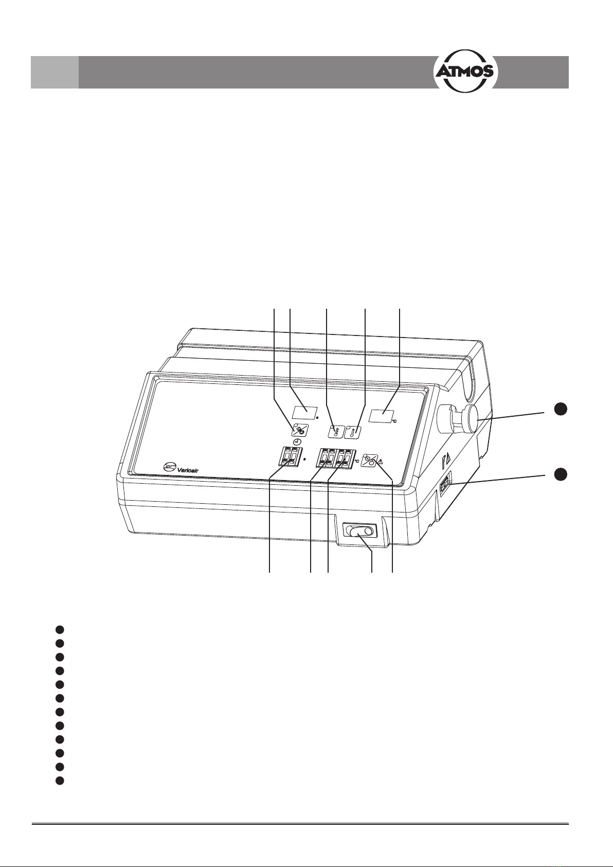
3.2 Illustrations
Fig. 1. Front view
1Main switch
2 Key switch for heating/air ow ON/OFF (standby)
3Coding switch for warm stimulation level
4Coding switch for cold stimulation level
5Coding switch for stimulation time
6 Key switch for selecting the warm stimulation level (e.g., 44 °C)
7 Key switch for selecting the cold stimulation level (e.g., 30 °C)
8 Key switch for start/stop of the stimulation
9 Temperature display (two-gure number, increment of 1 °C), actual value indication
10 Display of stimulation time (two-gure number, increment of 1 s)
11 Support for handle
12 Connection for handle
11
12
6
3.0 Setting up and starting up
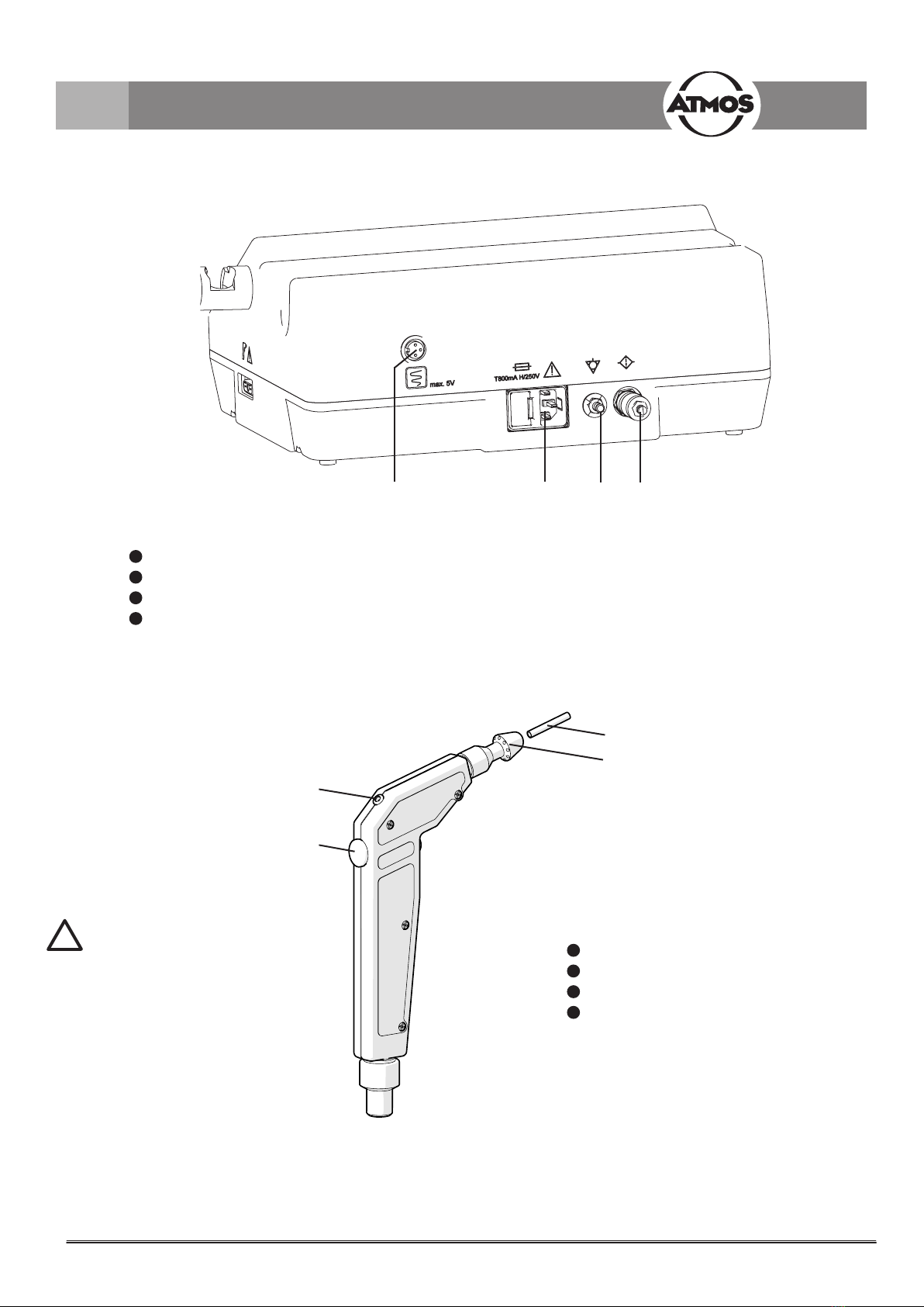
Fig. 2. Rear view
1Control output for controlling a nystagmograph
2Device plug with fuse compartment
3Equipotential bonding connection
4 Air lter (throttle silencer)
Fig. 3. Handle
1LED for indicating the stimulating process
2Timer Start/Stop key
3 Hose tip
4Jet connection
The sprayer nozzle must be
exchanged after each patient.
!
7
3.0 Setting up and starting up

3.3 Connections
3.3.1 Electrical connection
• Connect the power cable to the socket on the unit (,
Fig. 2).
• Insert the power plug in a correctly installed socket with
earthing contact.
3.3.2 Connecting a nystagmograph
• When controlling an ENG (electro-nystagmograph) or a
CNG (computer nystagmograph) at output (, Fig. 2),
please connect only recording equipment approved by
ATMOS. Connecting cable available from ATMOS (see
chapter 8.0).
3.3.3 Equipotential bonding conductor connec-
tion
• Connection for potential equalization (, Fig. 2). Con-
necting cable available from ATMOS (see chapter 8.0).
3.3.4 Connecting the handle
• Only the handle that is intended for this purpose must be
used:
- Press the special connector plug slightly onto the
socket in the unit.
- Fasten it to the housing by turning the holding screws
to the right.
)Do not kink the air tube!
3.3.5 Air inlet
• The ambient air is sucked into the unit through the lter.
• Screw connector for the air lter.
3.4 Starting up
• Insert the handle in its holder; the air outlet must point to
reverse side of the unit.
• Switch on the unit (, Fig. 1).
• Automatic display test with digital numbers “8 8” and
acoustic warning signal.
• Automatic change to standby mode.
8
3.0 Setting up and starting up
• Use the main switch to start the unit.
• Readiness for operation after 1 second.
• Completely press the hose tip onto the handle.
If the hose tip is not completely attached onto the handle,
damage could be caused to the patient’s eardrum.
4.1 Adjusting temperatures
• Two variable temperature levels (20 °C ‒ 47 °C) (48 °C +
49 °C only for testing purposes).
)The lowest achievable stimulation temperature is approx.
2 °C over the ambient temperature.
• Temperature setting by coding switches (, , Fig. 1).
- Left switch: for adjusting the “ten” partition
- Right switch: for adjusting the “one” partition
ªLower keys (+): temperature increase
ªUpper keys (-): temperature decrease
• Standard settings:
- Level for cold stimulation: 30 °C
- Level for warm stimulation: 44 °C
Avoid bending the tip of the hose within the ear / auditory
canal. Otherwise, the error “F1” or “F7” may occur.
4.2 Selecting temperature levels
• For selecting the desired temperature level, use the
respective key (, , Fig. 1).
ªDisplay of the active level via LEDs.
ªDisplay of the air temperature (current value) in °C.
• For switching o the heating system, press the respective
key (, , Fig. 1) of the active temperature level.
ªLED of the temperature level goes out.
ªDisplay of the air temperature (current value) in °C.
4.3 Adjusting stimulation time
• By means of coding switch (, Fig. 1).
!
!
4.4 Description of operating modes
4.4.1 Preparation mode
Purpose:
The temperature set by the user is adjustable.
Properties:
• Temperature: corresponds to the preselected cold or
warm stimulation level.
• Air ow: 5.0 l/min.
Activation:
• By operating one of the key switches for selecting a
temperature level (, , Fig. 1) or by operating the key
switch for heating/air ow ON/OFF (, Fig. 1) in the
standby mode.
• If the active temperature push button is pressed repeat-
edly, the heating is switched o.
ªAir with a temperature that almost corresponds to the
ambient air temperature is available.
Deactivation:
• Operating the key switch heating/air ow ON/OFF (,
Fig. 1) switches the unit to the standby mode.
• Automatic switch to standby mode when the unit is not
used within a 3-minute period.
9
4.0 Operation
4.4.2 Stimulation mode
Purpose:
Stimulation of the vestibular organ.
Properties:
• Temperature: corresponds to the preselected cold or
warm stimulation level.
• Air ow: 5.0 l/min.
• Duration: as pre-set by the timer.
Activation:
• Initially select the type of stimulation by activating either
the warm stimulation or cold stimulation key (, , Fig.
1) (see chapter section 4.1 for presetting of temperature).
• Recommended settings for Germany: 27 °C or
44 °C at 45 s.
• Operate the “timer start key” on the unit or on the handle.
• Preparation for stimulation:
- As long as the push button is pressed, the pump
remains switched o to allow the nozzle to be posi-
tioned in the auditory canal.
• When the push button is released, the thermal stimulation
is performed for the time set by the user (, Fig. 1).
ªLED on handle (, Fig. 3) lights up during thermal
stimulation.
• At the end of the stimulation period, a control signal for a
recording unit is issued at the nystagmograph output.
• After completion of stimulation, the pump is switched o.
• Repeated activation of the “timer start key” during stimu-
lation stops timer operation.
• Second activation of the currently active key deactivates
the corresponding level.
ªHeating is switched o.
ªStimulation with near-ambient air temperature.
Hose tip for the nozzle may not be blocked.
4.4.3 Standby mode
Purpose:
• Reduction of energy consumption.
• Reduction of noise level.
Activation:
• Activation of key “heating/pump on/o” (, Fig. 1).
ªHeating is switched o.
ªPump is switched o after 2 s.
• Automatically after each stimulation process.
• Automatically when the unit is not used within a 3-minute
period.
!
10
4.0 Operation
5.1 General information on cleaning and
disinfection
After use, all parts that come into contact with the patient (jet
connection) must be removed and disinfected! The cleaning
agents and disinfectants listed in section 5.2 are all suitable.
Hose tips must be exchanged after each patient.
The handle is not autoclavable!
The surfaces of the Varioair 3 resist most common surface
disinfectants.
However, do not use
• disinfectants that contain concentrated organic or inor-
ganic acids as they could cause corrosion damage.
• disinfectants containing chloramides, phenol derivatives,
or anionic surfactants, as these may cause stress cracks
in the material used for the housing of the unit.
You may also use disinfectant sprays or disinfectant tissues
for cleaning and disinfection.
)Set main switch of the device to OFF prior to cleaning
and disinfection. Wipe the unit surface with a cloth mois-
tened with a cleaning or disinfecting solution. Take care
that no liquid penetrates the device. The cleaning agents
and disinfectants listed in section 5.3 are all suitable.
)Always observe the instructions for use by the manu-
facturer of the disinfectants, including all concentration
specications.
)The described actions relating to cleaning and disinfec-
tion or sterilization do not substitute the relevant instruc-
tions which must be adhered to prior to operation.
5.2 Recommended instrument disinfectants
Disinfectant Ingredients in 100 g Manufacturer
Sekusept®PLUS
(concentrate)
Glucoprotamin 25 g Henkel, Düsseldorf
Nonionic surfactants, solvents, complexing agents
Gigasept®FF
(concentrate)
Succindialdehyde 11.0 g Schülke & Mayr, Norder-
stedt
Dimethoxytetrahydrofurane 3.0 g
Corrosion protection components, non-ionic surfactants,
and perfumes
Mucocit®-T new
(concentrate)
Bis(3-aminopropyl)laurylamine 8.0 g Merz & Co., Frankfurt/Main
Alkyldimethylbenzylammonium chloride 19.0 g
Cocospropylendiamin-1,5-guanidinium-acetate 7.0 g
5.3 Recommended surface disinfectants
Disinfectant Ingredients in 100 g Manufacturer
TERRALIN
(concentrate)
Benzalkonium chloride 20.0 g Schülke & Mayr, Norder-
stedt
Phenoxypropanols 35.0 g
Hexaquart®forte Benzyl-C12-16 alkyldimethyl, chlorides 20 g BBraun, Melsungen
Didecyldimethylammonium chloride 7.9 g
Non-ionic surfactants 5 – 15%
NTA < 5 %
Incidin Plus
(concentrate)
Glucoprotamin 26.0 g Henkel, Düsseldorf
Non-ionic surfactants
Solvents, complexing agents
Pursept-A
(Disinfectant spray or
disinfectant cloths)
Ethanol 38.9 g Merz & Co., Frankfurt/Main
Glyoxal 0.1 g
Quaternary ammonium compounds 0.05 g
When using disinfectants containing aldehyde and amine on the same object, color changes may occur.
11
5.0 Cleaning and care

Maintenance, repairs, and periodic tests may only be carried out by persons who have the appropriate technical knowledge and
are familiar with the product. To carry out these measures, the person must have the necessary test devices and original spare
parts.
ATMOS recommends: Work should be carried out by an authorized ATMOS service partner. This ensures that repairs and test-
ing are carried out professionally, original spare parts are used, and warranty claims remain unaected.
Carry out an inspection according to the manufacturer’s specications every 12 months.
6.1 Sending in the device
• Remove and properly dispose of consumables.
• Clean and disinfect the product and accessories according to the operating instructions.
• Place any used accessories with the product.
• Fill in the form QD 434 “Delivery complaint / return shipment” and the respective Decontamination certicate.
)This form is enclosed with each delivery and can be found at www.atmosmed.com.
• The device must be well padded and packed in suitable packaging.
• Place form QD 434 “Delivery complaint / return shipment” and the respective Decontamination certicate in an envelope.
• Ax the envelope to the outside of the package.
• Send the product to ATMOS or your dealer.
12
6.0 Maintenance and service

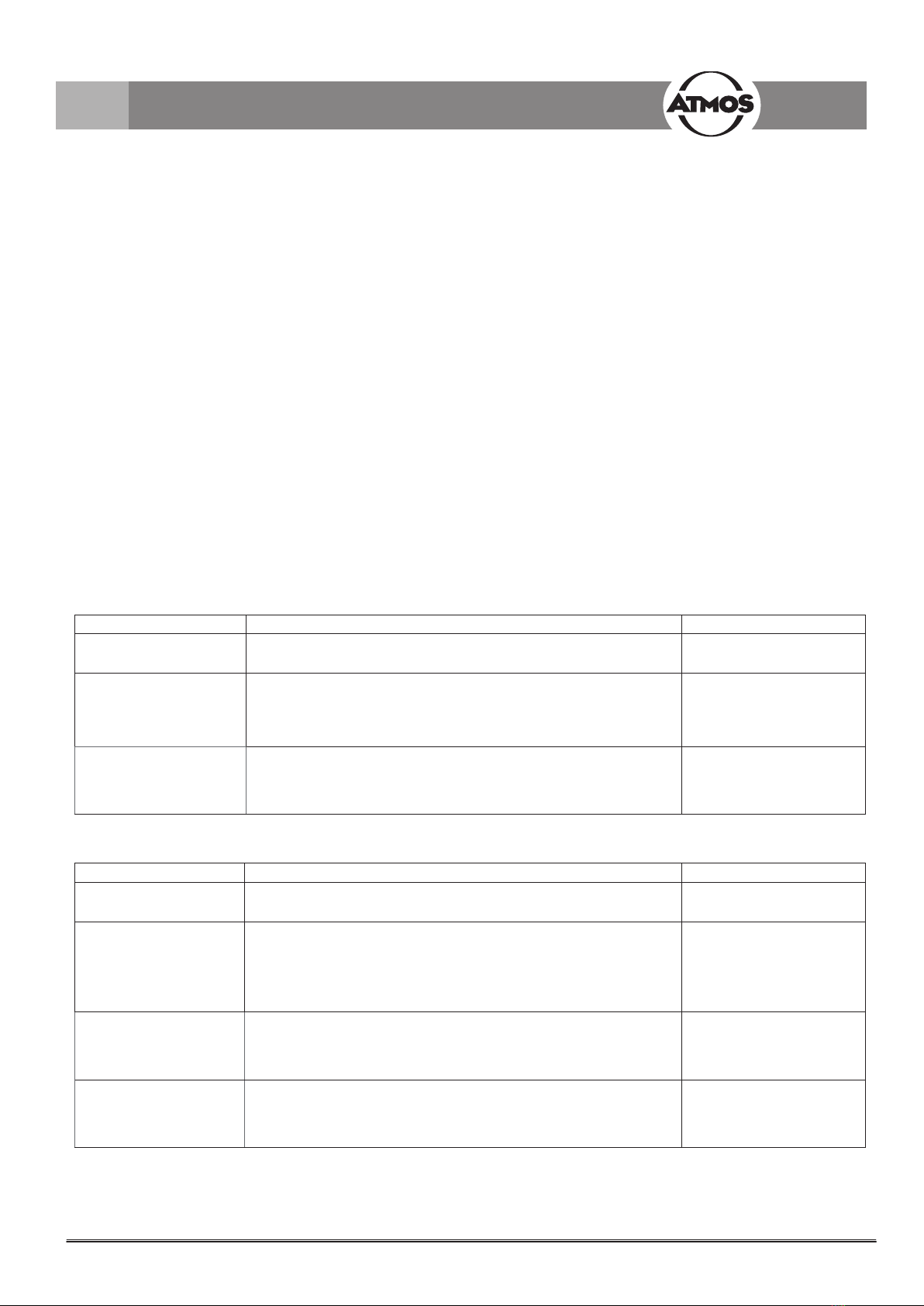
Error in temperature
display
Possible cause Remedy
“F0” Not used
“F1” Maximum allowed temperature
exceeded (>51 °C) (if the tempera-
ture exceeds 51 °C for more than 2
seconds, the pump is switched o
automatically).
• Switch o device, cooling down for approx. 1 minute is
required.
• Check whether temperature setting is too high. If neces-
sary, adjust desired temperature to a value of <51 °C by
means of the coding switches.
• Inform the service sta.
• Bent hose tip within the ear / auditory canal.
“F2” -5 V is missing (supply voltage on
the controller board)
• Inform the service sta.
“F3” Break of the safety NTC • Check proper connection of the handle.
• Replace the handle.
• Inform the service sta.
“F4” Not used
“F5” Break of the regulating NTC • Check proper connection of the handle.
• Replace the handle.
• Inform the service sta.
“F6” Not used
“F7” Temperature too high (>48 °C) • Check whether temperature setting is too high. If neces-
sary, adjust desired temperature to a value of <48 °C by
means of the coding switches.
• Inform the service sta.
• Bent hose tip within the ear / auditory canal.
“F8” Short-circuit of the regulating NTC • Replace the handle.
• Have temperature feeler of the regulating NTC checked by
the service sta.
“F9” Not used
)If errors cannot be corrected with the assistance of the troubleshooting list, please inform the service sta or send in the
device for repair. Do not start any attempts to repair the unit yourself!
13
7.0 Troubleshooting

8.1 Accessories
Description .....................................................................................................................................................REF
Power cable .....................................................................................................................................................507.0859.0
Handle, complete .............................................................................................................................................502.1035.0
Hose tips for jet (30 pcs.) .................................................................................................................................502.0844.0
8.2 Spare parts
Description .....................................................................................................................................................REF
Device base .....................................................................................................................................................000.0796.0
Fuse T 800 mA / H 250V 5x20 mm .................................................................................................................008.0081.0
Power cable .....................................................................................................................................................507.0859.0
Handle, complete .............................................................................................................................................502.1035.0
Jet connection ..................................................................................................................................................502.1045.0
Hose tips for jet (30 pcs.) .................................................................................................................................502.0844.0
14
8.0 Accessories and spare parts

Voltage range 100 - 240 V~ ± 10 %; 50/60 Hz
Current consumption max. 0.75 A
Power consumption max. 85 W
Connections Mains connection via IEC socket;control output for a nystagmograph; equipotential equal-
ization; connection for the handle; air inlet
Fuses 2 x T 1.6 A (f. 250 V~, 50/60 Hz)
Stimulation time Can be preselected by timer from 1 up to 99 sec.
Timer indication Indication accuracy ± 0.5 s ± ½ digit
Air temperature 20°C - 47°C
Lowest temperature Approx. 2°C above room temperature
Temperature indication Indication accuracy ± 0.5 s ± ½ digit
Temperature deviation < ± 1°C
Air ow 5.0 l/min ± 10 %
Operating time Short term operation:
1. Automatic shut-o after completion of stimulation.
2. Automatic shut-o after 3 minutes.
Modes of operation Preparation mode; stimulation mode (at temperature preselected for the cold stimulation
level resp. warm stimulation level); heating o and no air ow (economy mode, standby
mode)
Protective earth conductor
resistance
max. 0.1 Ω
Earth leakage current max. 0.5 mA
Enclosure leakage current max. 0.1 mA
Patient leakage current max. 0.1 mA
Ambient conditions for trans-
port/storage
-20...+50°C; 5...90 % humidity without condensation at air pressure 700...1060 hPa
Ambient conditions operation +10...+35°C; 20...80 % humidity without condensation at air pressure 700...1060 hPa
Maximum operational altitude ≤ 3000 m (NN)
Contamination level Class 2
Overvoltage category II
Dimensions HxWxD 14.5 x 37 x 32 cm
Weight 3.7 kg
Period tests Inspection according to the manufacturers specications every 12 months.
Safety class (EN 60601-1) I
Degree of protection Type B
Protection class IPX0
Further classications accord-
ing to other regulations
VDE protection class 1 (IEC 601/EN 60601)
Classication according to
Appendix IX EC Directive 93/42/
EEC
Class IIa
CE marking CE 0124
Applied standards EN 60601-1: 1990 + A1:1993 + A2:1995
EN 60601-1-2: 1993 (EMV / EMC)
GMDN code 34891
UMDNS code 10-548
ID No. (REF) 502.1100.0
Issue of the technical data: 2016-12-23
15
9.0 Technical data

• Packaging material, cardboard, and/or PE foam can be
fully recycled or returned to your supplier.
• The Varioair 3 does not contain any hazardous materials.
• The housing is fully recyclable.
• The component parts of the Varioair 3 must be disposed
of correctly and the materials are to be separated care-
fully.
• The electronics circuit boards must be fed into the appro-
priate recycling process.
• Used hose tips that no longer can be disinfected must be
discarded into domestic waste immediately.
16
10.0 Disposal

11.1 Guidelines and Manufacturer’s Declaration ‒ Emissions
The Varioair 3 is designed for operation in the environment specied below. The customer or user of the Varioair 3 should ensure
that it is used in such an environment.
Emissions Test Compliance Electromagnetic Environment ‒Guidance
RF Emissions acc.to CISPR 11 Group 1 The Varioair 3 uses HF energy for its internal functions. There-
fore, its RF emissions are very low and are not likely to cause any
interference in nearby electronic equipment.
RF Emissions acc. to CISPR 11 Class B
The Varioair 3 is suitable for use in all establishments, including
domestic and those connected directly to a public power supply
network that supplies buildings used for residential purposes.
Harmonic emissions according to
IEC 61000-3-2
Class A
Voltage uctuations/icker according
to IEC 61000-3-3
Corresponds
11.2 Guidelines and Manufacturer’s Declaration ‒ Immunity
The Varioair 3 is designed for operation in the electromagnetic environment specied below. The customer or user of the Varioair 3
should ensure that it is used in such an environment.
Immunity Test IEC 60601 Test
Level Compliance Level Electromagnetic Environment ‒Guidance
Electrostatic dis-
charge (ESD) accord-
ing to IEC 61000-4-2
± 6 kV Contact
± 8 kV Air
Floors should be made of wood or concrete or laid
with ceramic tiles. If oors are synthetic, the relative
humidity should be at least 30 %.
EFT IEC 61000-4-4 ± 2 kV Mains
± 1 kV I/Os
Mains power quality should be that of a typical com-
mercial or hospital environment.
Surges IEC 61000-
4-5
1 kV
Common
2 kV
Dierential
Mains power quality should be that of a typical com-
mercial or hospital environment.
Magnetic eld at pow-
er frequency 50/60 Hz
acc. to IEC 61000-4-8
3 A/m Power frequency magnetic elds should be that of a
typical commercial or hospital environment.
• Medical electrical equipment is subject to special precautions with regard to EMC and must be installed according to the follow-
ing EMC notes.
• Portable and mobile RF communication facilities can inuence medical electrical equipment.
• The use of other accessories, converters, and cables than stated may lead to an increased emission or a reduced interference
immunity of the equipment or system.
The device may not be used directly next to other devices or piled up with other devices. If operation next to or piled with other
devices is necessary, please watch the device to check its intended operation in this arrangement.
17
11.0 Notes on EMC
Immunity Test IEC 60601 Test Level Compliance Level Electromagnetic Environment ‒ Guidance
Voltage Dips / Dropout
IEC 61000-4-11
< 5 % UT
(> 95 % Dip of the UT)
for 0.5 Cycle
40 % UT
(60 % Dip of the UT)
For 5 cycles
70 % UT
(30 % Dip of the UT)
For 25 cycles
< 5 % UT
(> 95 % Dip of the UT)
for 5 s
Mains power quality should be that of a typical
commercial or hospital environment. If the user
of the Varioair 3 requires continued operation
upon the occurrence of disruptions in the energy
supply, the Varioair 3 should make use of an
uninterruptible power supply or a battery.
NOTE UTis the mains alternating current prior to application of the test levels.
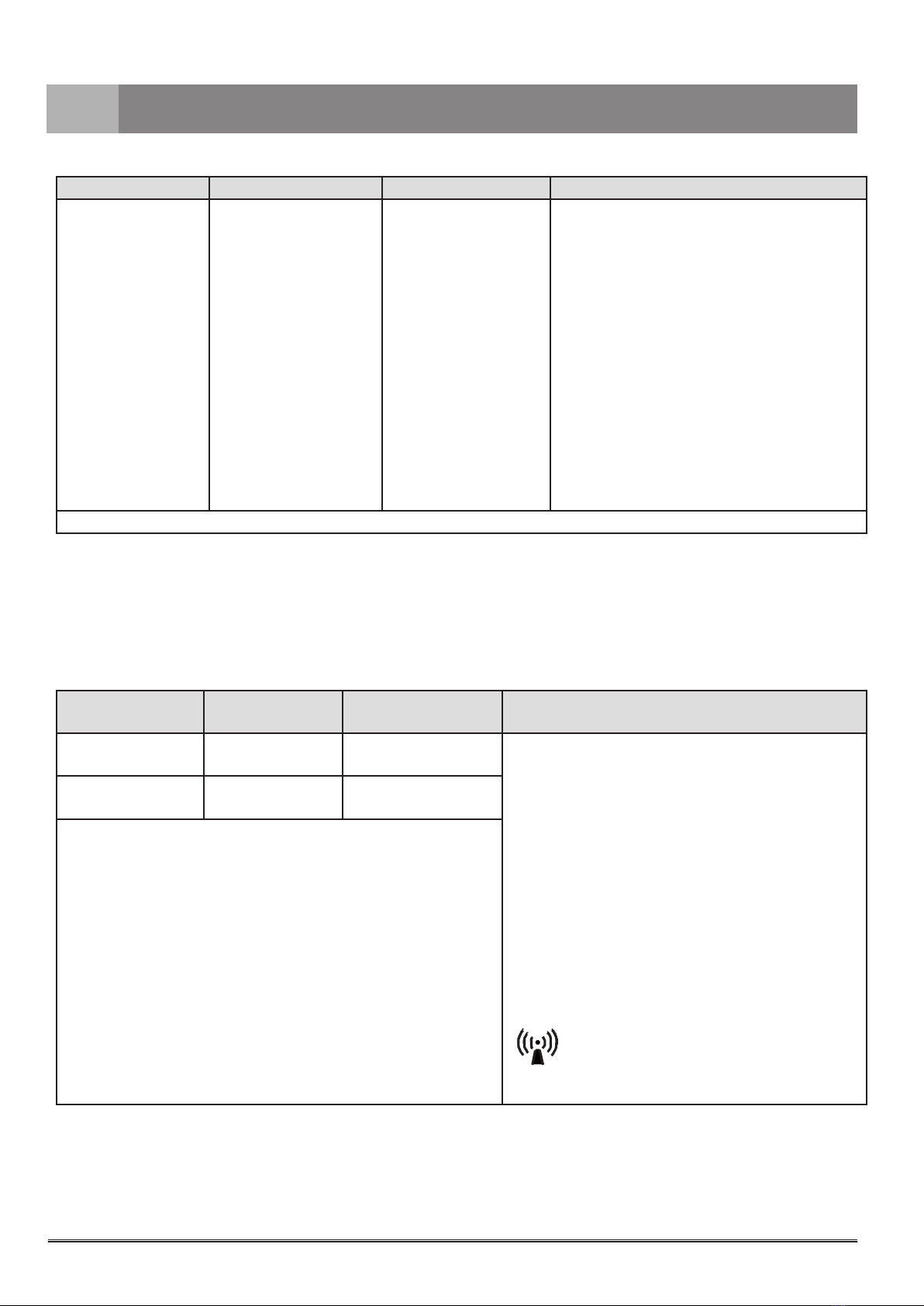
11.3 Guidelines and Manufacturer’s Declaration ‒ Immunity
The Varioair 3 is designed for operation in the electromagnetic environment specied below. The customer or user of the Varioair 3
should ensure that it is used in such an environment.
Immunity Test IEC 60601 Test
Level Compliance Level Electromagnetic Environment ‒ Guidance
Conducted RF IEC
61000-4-6
3 Ve
150 kHz to 80 MHz [3 ] V Portable and mobile radio equipment should be used no
closer to the Varioair 3, including cables, than the rec-
ommended distance calculated according to that which
applies to the transmission frequency.
Recommended distances:
d = [ 1,2] √P
d = [ 1,2] √P
d = [ 2,3] √P
where P is the max. power in watts (W) and d is the
recommended separation distance in meters (m).
Field strengths from xed transmitters, as determined by
an electromagnetic site (a) survey, should be less than
the compliance level (b).
Interference may occur in the vicinity of equipment con-
taining following symbol:
Radiated RF IEC
61000-4-3
3 V/m
80 MHz to 2.5 GHz
[3 ] V/m
18
11.0 Notes on EMC

11.4 Recommended separations between portable and mobile RF communications equip-
ment and the Varioair 3
NOTE 1
With 80 MHz and 800 MHz, the higher frequency range applies.
NOTE 2
These guidelines may not be applicable in all cases. The emanation of electromagnetic waves is aected by absorption and
reection of buildings, objects, and people.
a
The eld strength of stationary transmitters, such as base stations of cellular phones and mobile terrain radio equipment,
amateur radio transmitters, cbm broadcast and TV stations cannot be predestined exactly. To determine the electromagnetic
environment in regard to stationary transmitters, a study of the location is to be considered. If the eld strength measured at the
site where the Varioair 3 is used exceeds the compliance level above, the Varioair 3 must be observed to demonstrate proper
function. If abnormal performance is observed, additional measures may be necessary, such as reorienting or relocating the
Varioair 3.
b
Within the frequency range of 150 kHz to 80 MHz, the eld strength should be below 3 V/m.
The Varioair 3 is intended for use in an electromagnetic environment in which HF disturbances are controlled. The customer or user
of the Varioair 3 can thereby help to prevent electromagnetic interference by maintaining a minimum distance between portable and
mobile RF communication equipment (transmitters) and the Varioair 3 – depending on the output of the communication device as
indicated below.
Safety distance, depending on transmit-frequency m
Nominal output of the
transmitter
W
150 kHz to 80 MHz
d = [ 1,2] √P
80 MHz to 800 MHz
d = [ 1,2] √P
800 MHz to 2.5 GHz
d = [ 2,3] √P
0.01 0.12 0.12 0.23
0.1 0.46 0.46 0.9
1 1.2 1.2 2.3
10 3.8 3.8 7.3
100 12 12 23
For transmitters for which the maximum nominal output is not indicated in the above table, the recommended safe-
ty distance d in meters (m) can be determined using the equation belonging to the respective column whereas P is
the maximum nominal output of the transmitter in watts (W) acc. to manufacturer’s specication.
NOTE 1
With 80 MHz and 800 MHz, the higher frequency range applies.
NOTE 2
These guidelines may not be applicable in all cases. The emanation of electromagnetic waves is aected by ab-
sorption and reection of buildings, objects, and people.
19
11.0 Notes on EMC

ATMOS MedizinTechnik GmbH & Co. KG
Ludwig-Kegel-Str. 16
79853 Lenzkirch / Germany
Phone: +49 7653 689-0
www.atmosmed.com
Other manuals for Varioair 3
1
Table of contents
Other Atmos Test Equipment manuals


Popular Test Equipment manuals by other brands


Envitec
Envitec AlcoQuant 6020 operating instructions

TSI Instruments
TSI Instruments 4046 user guide

Keysight Technologies
Keysight Technologies 16380V Operation and service manual

Cal Test Electronics
Cal Test Electronics CT3684 user manual

DMQ
DMQ QH5 U user manual

TRENDnet
TRENDnet TC-TP1 Product information